 bryan.lowder
*NOTE: The project is finished but I am still documenting-- I should be done by 10/31*
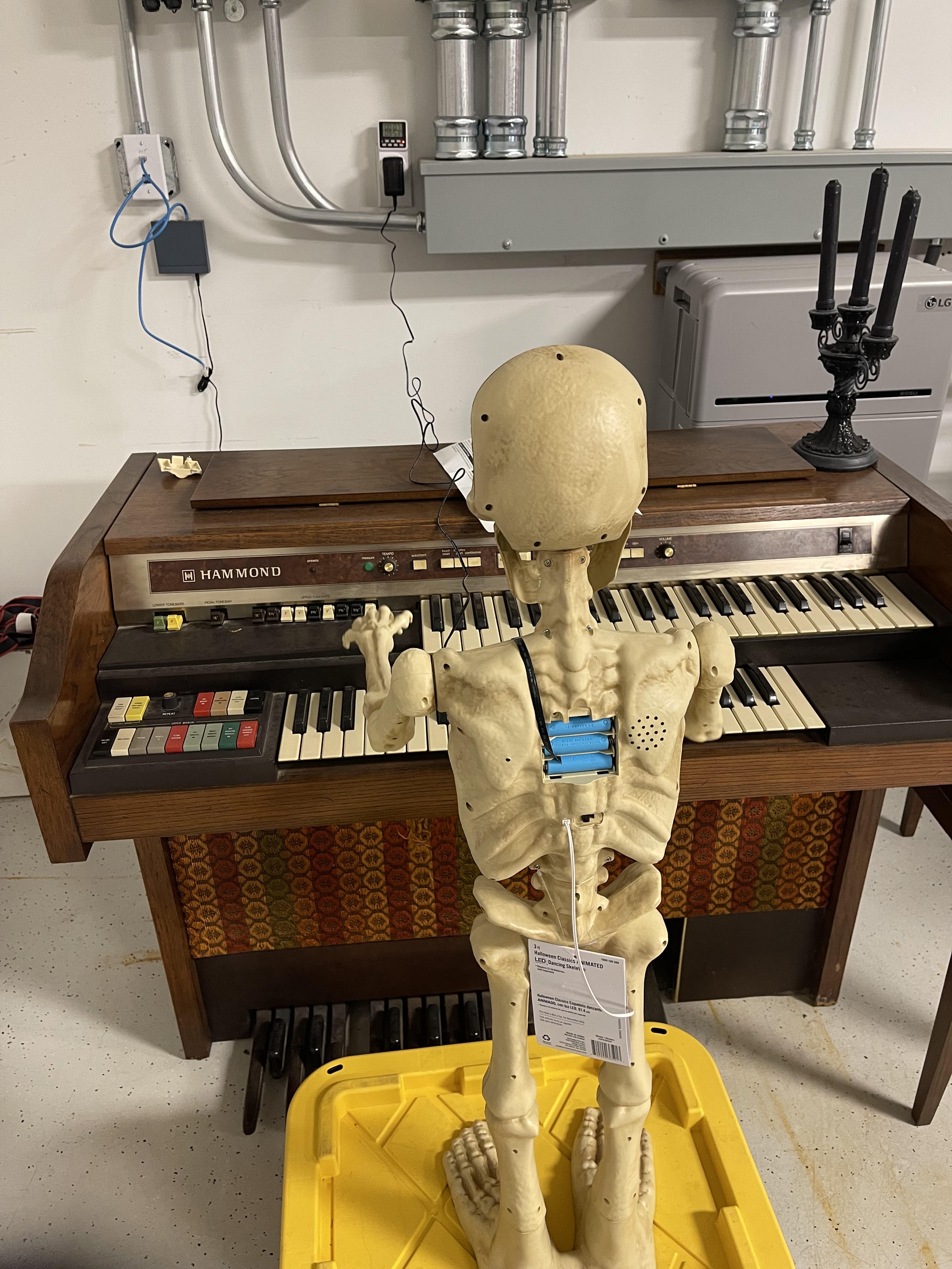
The Organ-Playing Skeleton is a project to make a ghostly or skeletal figure appear to play the organ.
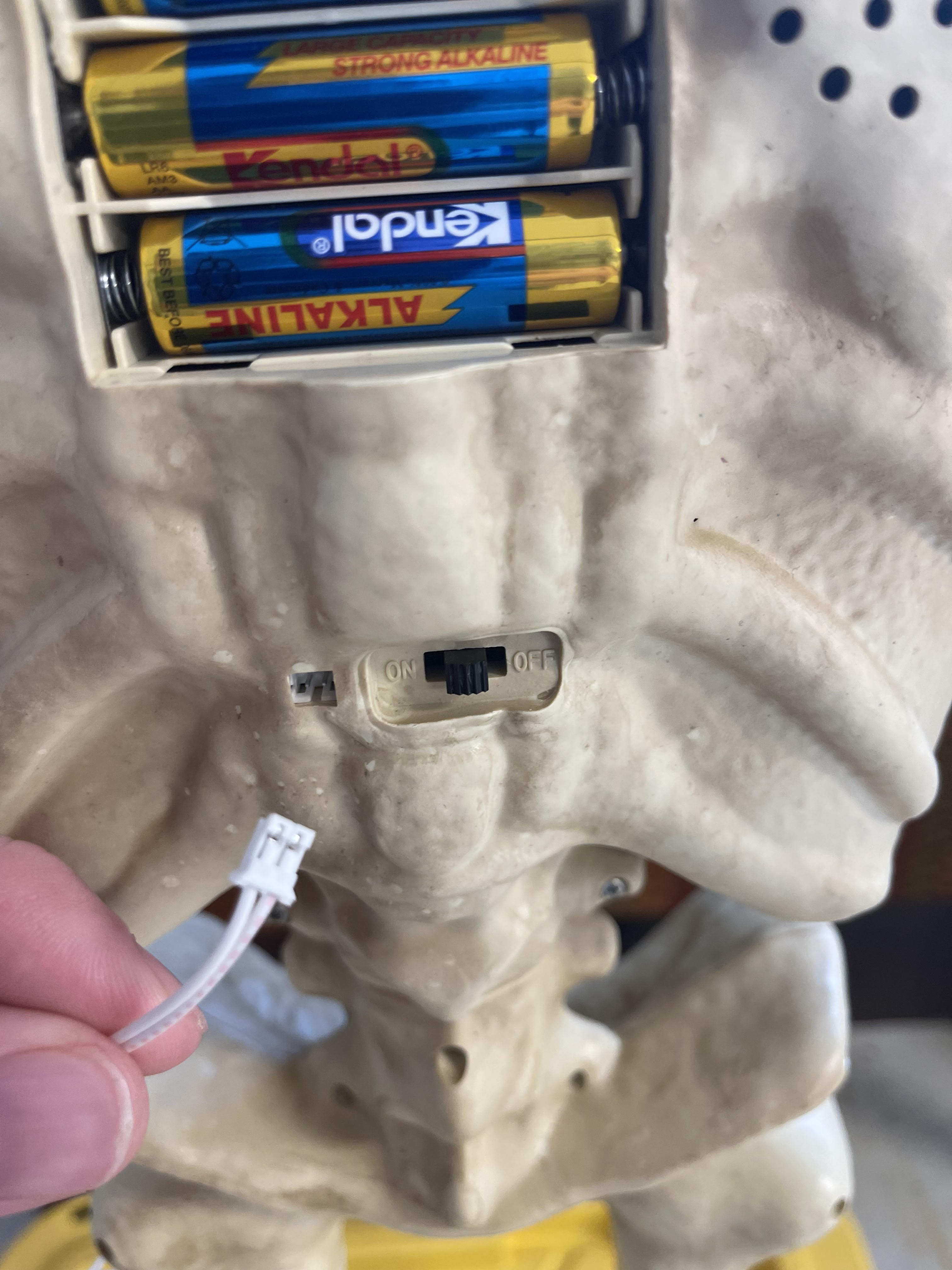
A goofy 3-foot tall animatronic from The Home Depot (tm) is used for the figure. This has an excellent motion for the purpose and can be triggered by pressing a DEMO button. This feature is hijacked to control when the motion starts.
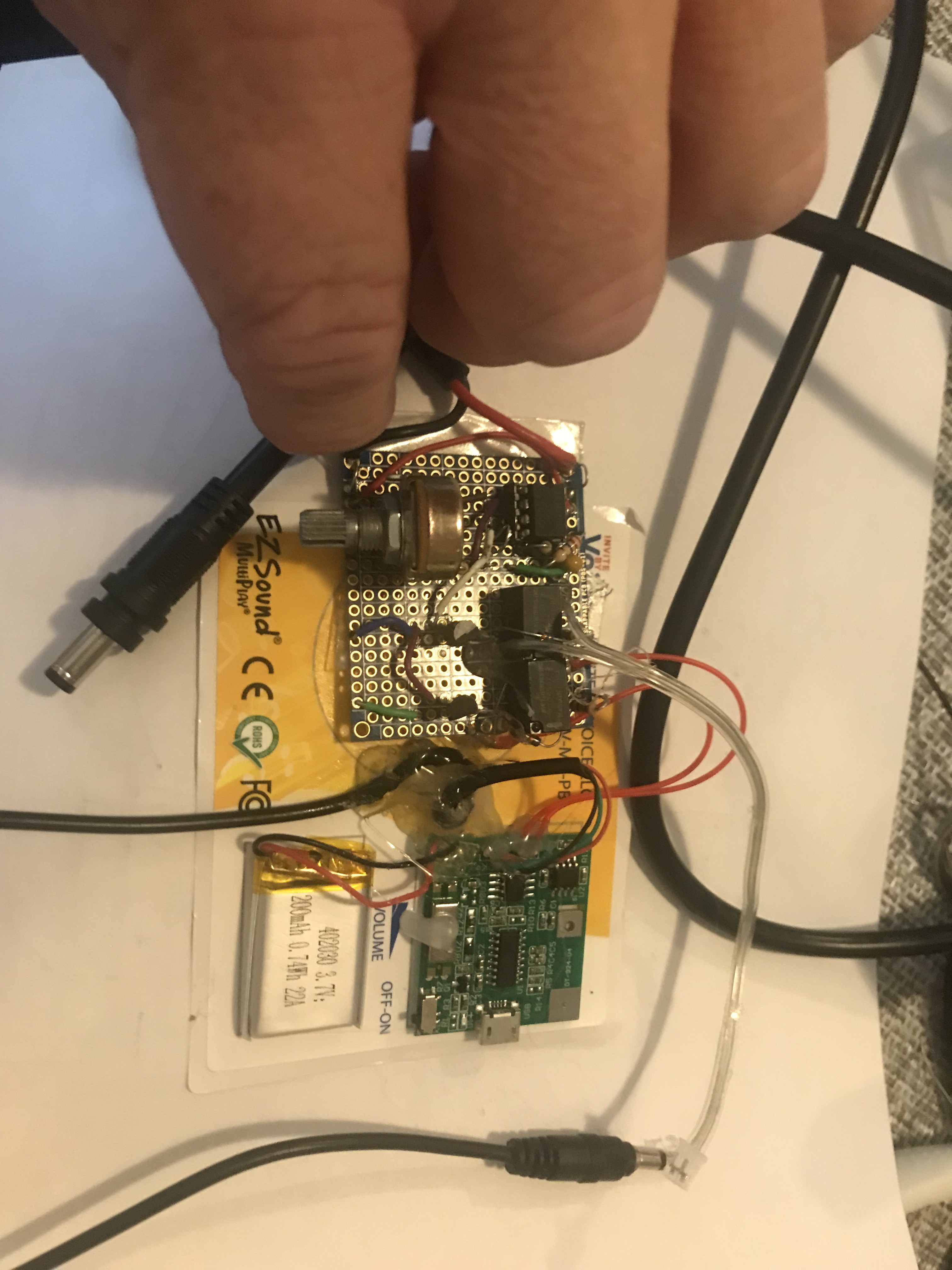
An MP3 player designed to be incorporated into greeting cards and the like was also purchased and modified to provide the music.
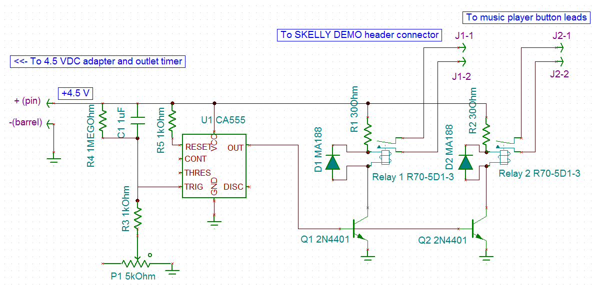
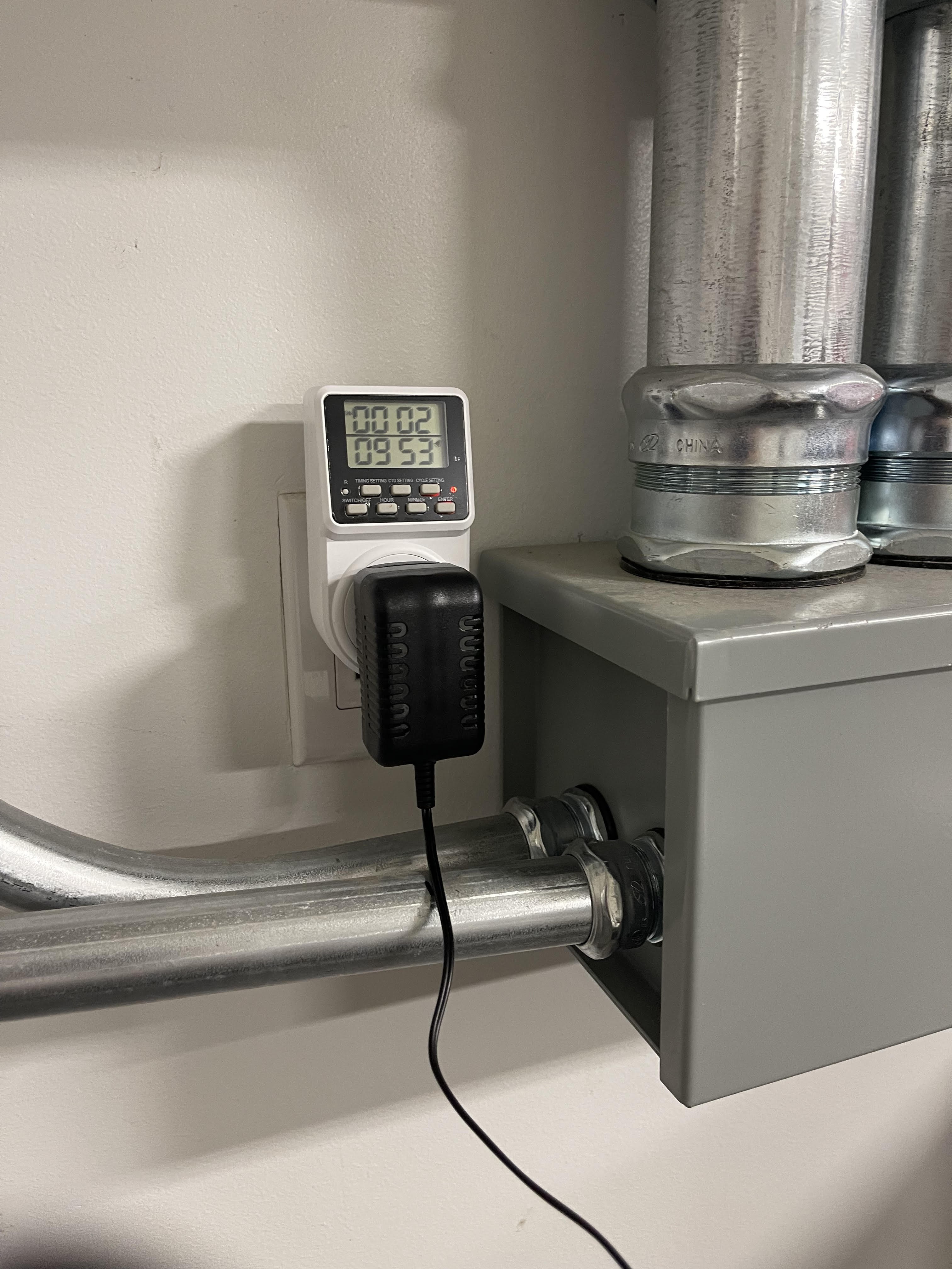
An outlet timer combined with an AC to 4.5V DC adapter provides power to the skeleton and triggers a custom controller, which turns on both skeleton and player after a brief delay. The organ is an inert prop.
This is the result:
A technical tour de force it ain't , but it is practical and it works and it was done on time.


 Yann Guidon / YGDES
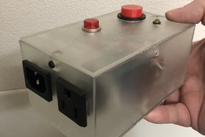
 Nick Sayer
 Emilio P.G. Ficara
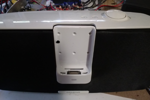
 Stefan Kratz