 Steve Dearden
Construction
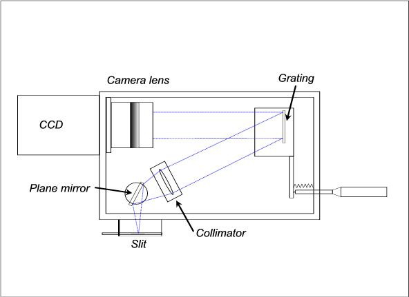
The design is significantly different to the "classical spectrograph" in that the input slit and CCD detector are at 90 degrees to each other. A schematic diagram of the basic components of can be seen here:
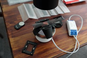
This next image shows the beginnings of the spectrometer showing a partially completed housing.
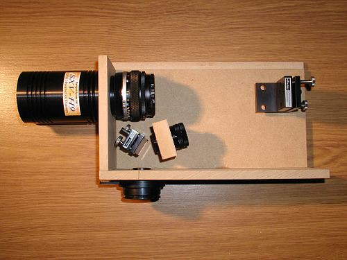
Since I do not have access to a metalworki shop but use only hand machine tools, my first choice for materials for the main body of the spectrometer was wood or wood composite (MDF). As an example, a block of MDF of dimensions 60x40x20 mm, with a 30 mm hole, serves as the support for the collimator lens and lens barrel as shown above. Nothing could be simpler!
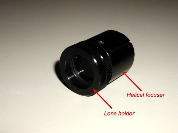
Below is an image of the collimator lens in its lens holder. The lens is an achromatic doublet with focal length of 90mm. A helical focusing tube, with a very fine thread, allows for small adjustments to be made for final collimation and is then locked in position with a small set screw. Available from Edmund Optics.
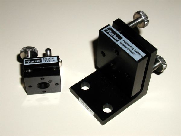
I chose to use commercially available supports for the front surface mirror and the grating mount. Since a wooden body lacks the rigidity of metal, good quality positioning mounts were selected so that more precise adjustments could be made (if needed) and any flexure compensated for. Commercial mounts like these can be obtained from companies such as Newport or Edmund Optics or Thorlabs.
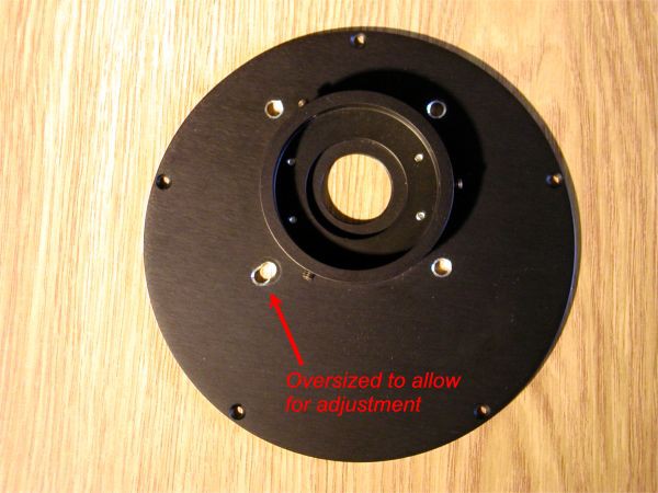
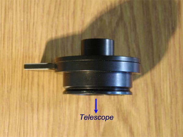
For connecting the spectrometer to the telescope, a circular plate from an old dismantled CCD camera was salvaged. Therefore never throw anything of potential future use away! The large central hole had been tapped to receive a standard CS-mount video camera lens. This is useful for times when you may want to record the spectra of non-astronomical light sources without the telescope:
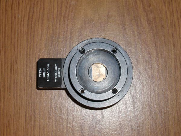
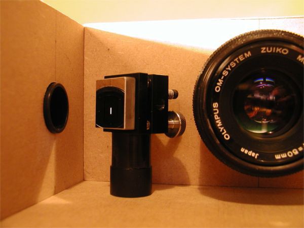
The next 2 images are of the slit holder with one of the interchangeable slits seen inserted on the side. This holder came from an Oriel MS125 1/8 metre focal length spectrograph. The slit holder fits snugly into a hole in the side of the spectrometer. Remember that with this spectrometer design the slit and detector are at 90° to each other. Using a plane front surface mirror just after light passes through the slit does result in some light loss (the mirror’s reflectivity is about 96%) but this was considered acceptable. The main advantage comes from the reduction in size of the whole instrument.
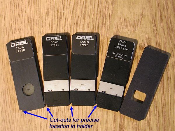
The next image is the family of 25, 50, 100 and 200 micron slits used with the spectrograph. Again, these originate from the MS125 and are available from Oriel-Newport Corp. or can be found on eBay. The “slit” on the right is simply a square hole that can be used for wide slit or slitless spectroscopy. The small square cut-out at the bottom right-hand corner of each slit enables the aperture to be positioned precisely and reproducibly at the centre of the slit holder (previous photos).
This next picture is a preliminary alignment test. I am observing from the position of the diffraction grating to check for correct plane mirror orientation. Fine adjustments with the collimator's helical focusing ring produced a sharp clear image of the slit which is now collimated. Thus light rays focused on the slit will be parallel when incident on the grating.
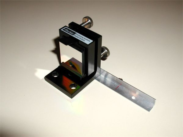
The following image shows the grating with a “rotation arm” bolted to the grating mount. This is simply a length of 10 mm angled aluminium strip and is used to provide controlled rotation of the grating when coupled to a micrometer adjustment screw. Just about visible in this picture, behind the angle bracket at the red line marking, is a knurled nut that has been glued to the arm at a precise position. Seated in the nut will be a small hardened steel ball which will maintain contact with a micrometer screw via a suitable spring attached to the arm and the rear wall of the spectrograph.
The mechanism used to...
Read more »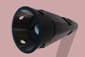
 David H Haffner Sr
 Stephen Holdaway
 Pavel
Pavel