 Tom Goff
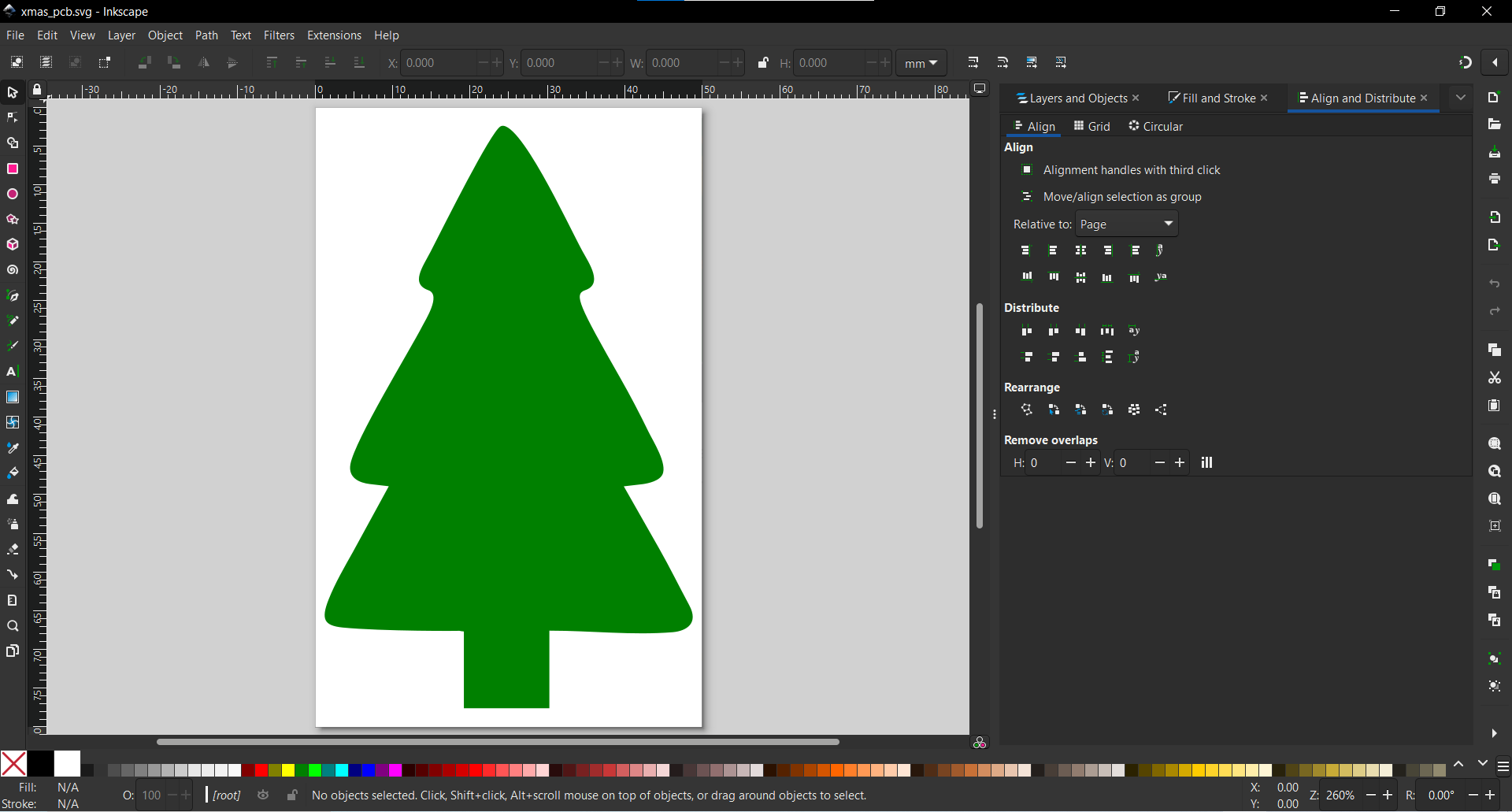
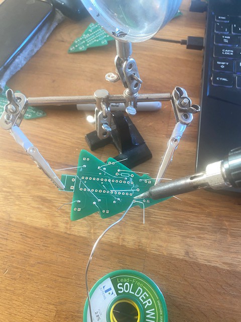
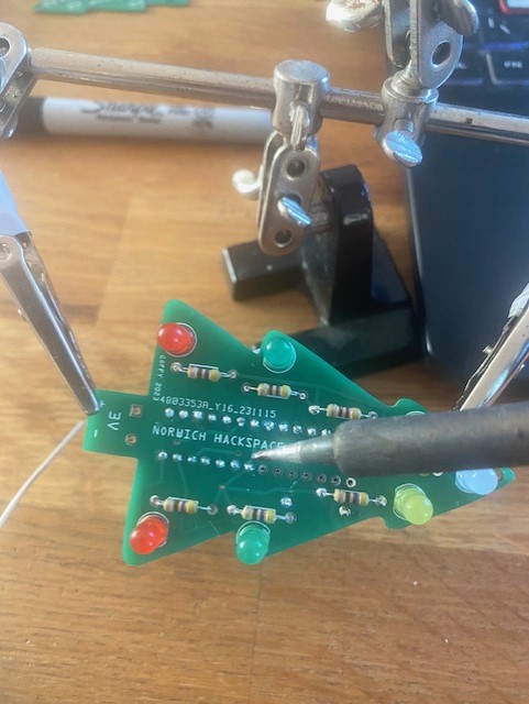
I tried to keep this project really simple to execute because it needed to be accessible to all the members of our hackspace. I have shared how I built the custom shaped PCB using simple to use open source software packages. This stage is no necessary is you just want to order the PCB and solder in all the components and program the microcontroller.
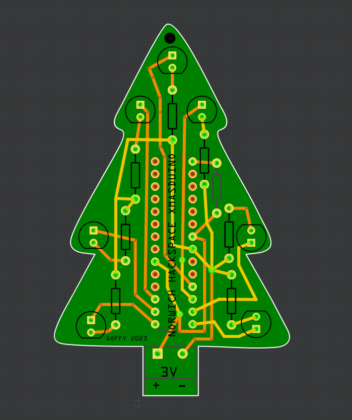
The PCB can be used as a desk or table decoration with the 2 x AAA battery pack or as a piece of festive jewellery with the smaller lighter 2 x CR2032 battery pack.

 Hendra Kusumah
 Jelto
Jelto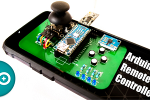
 Jithin Sanal
 Saimon