 Kevin Kessler
Meaning of Saturation Current
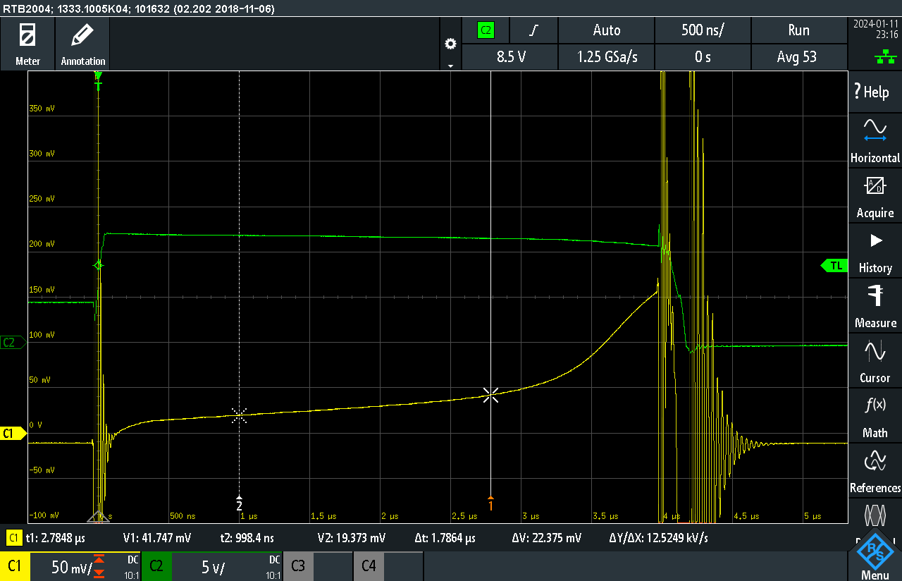
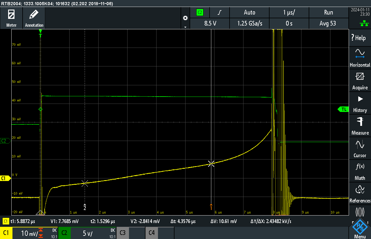
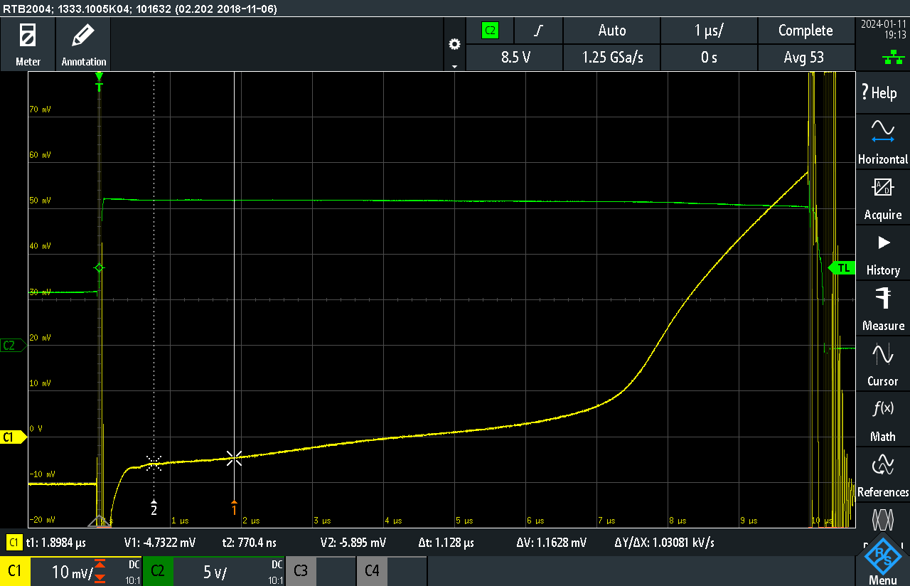
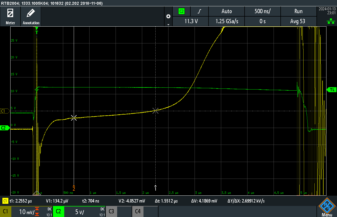
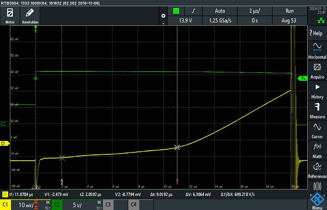
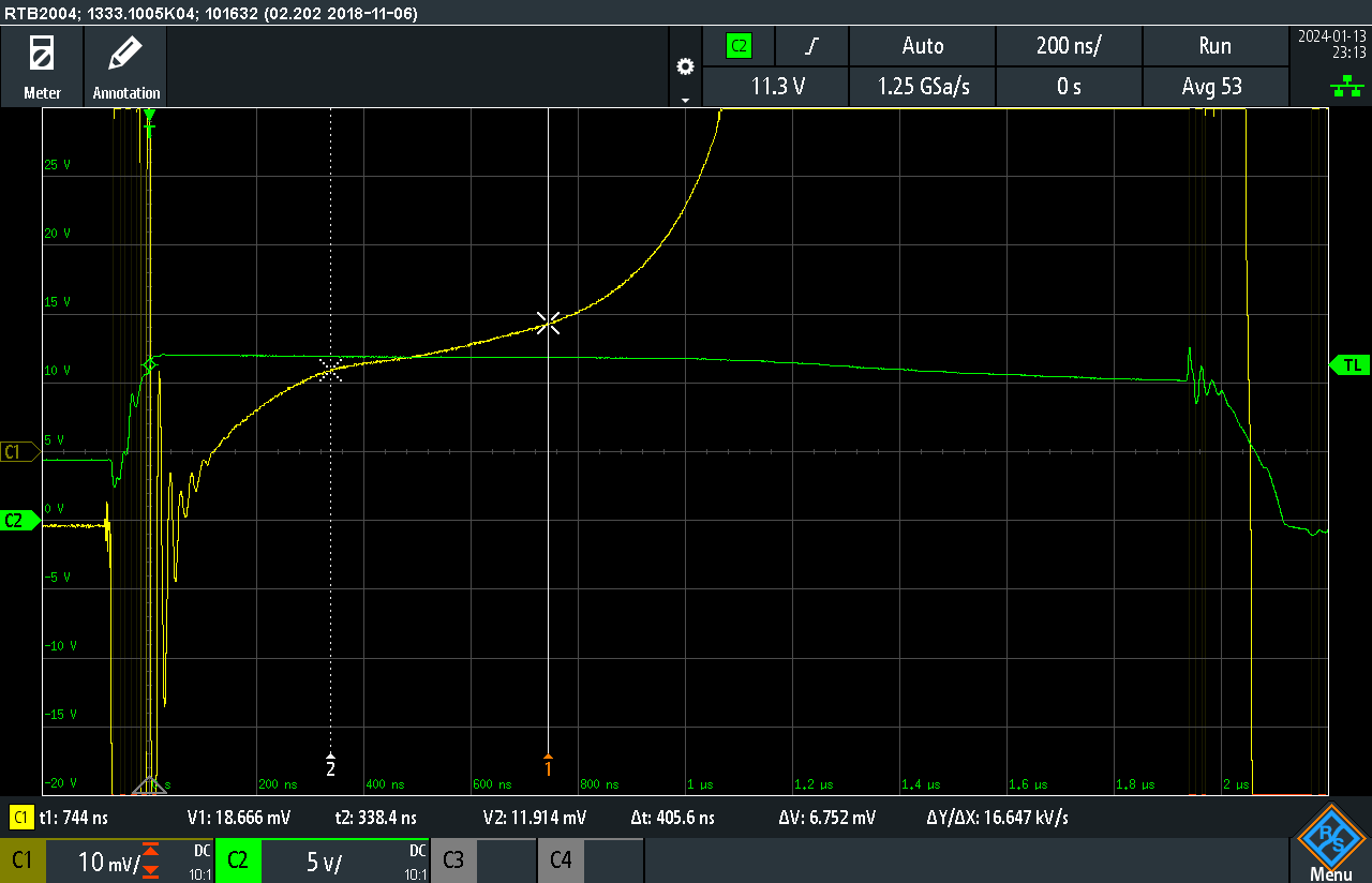
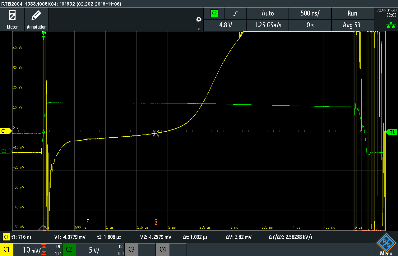
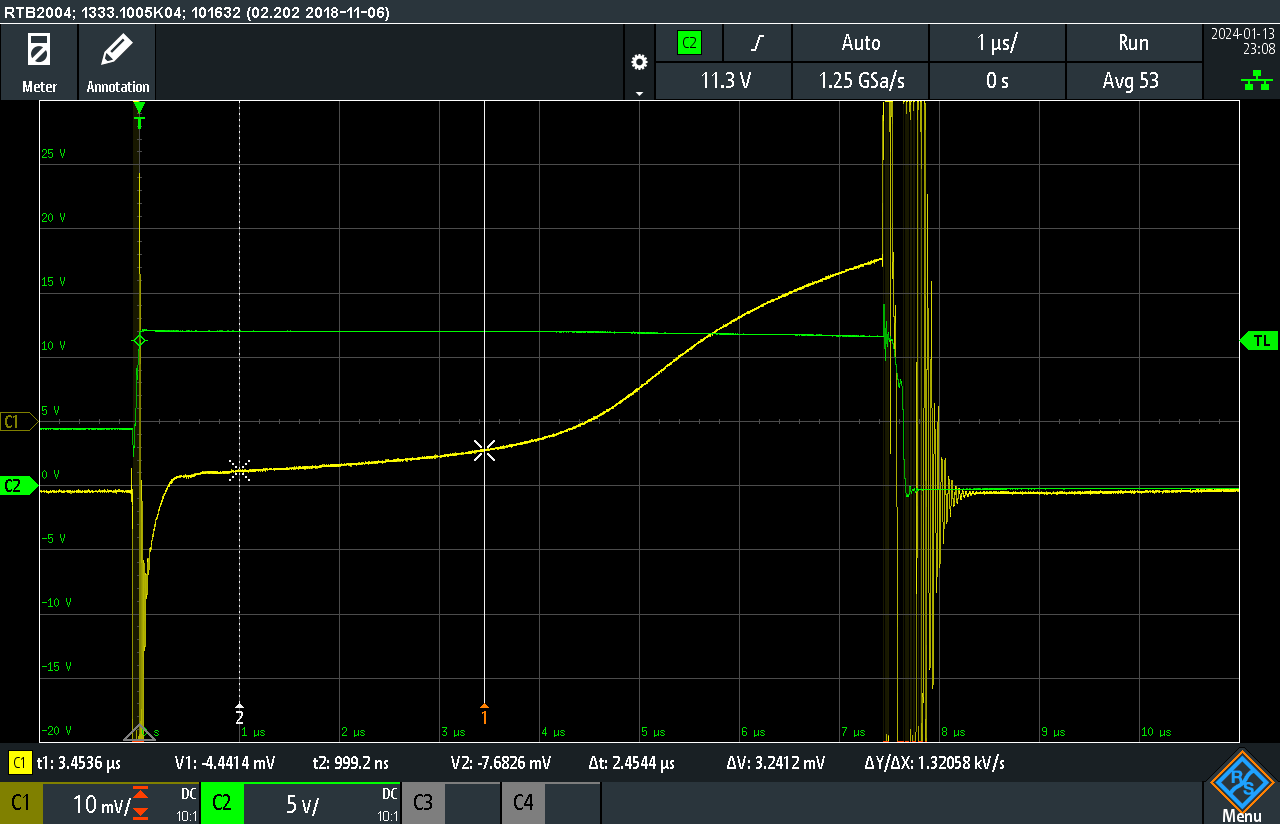
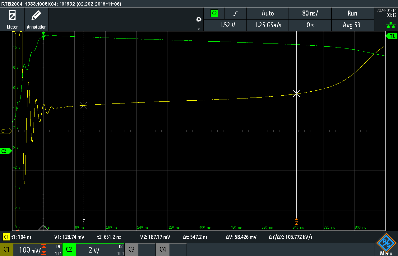
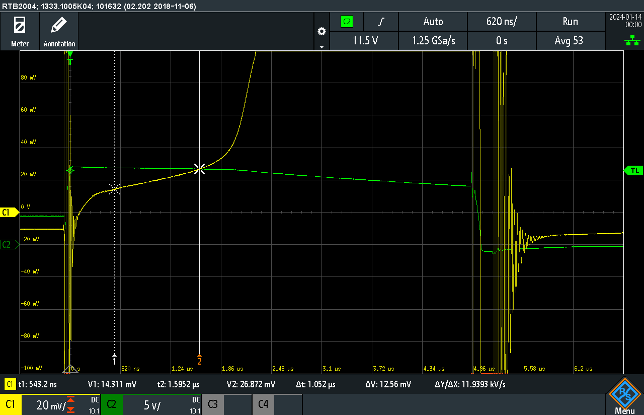
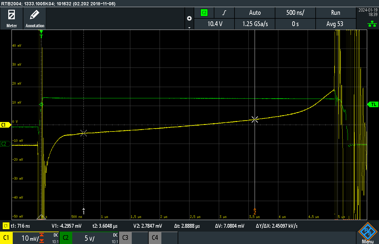
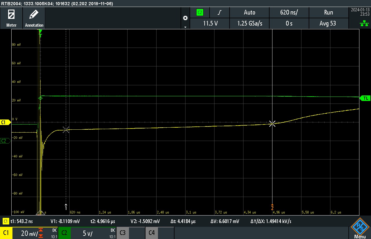
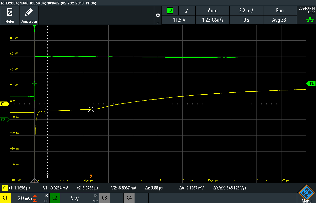
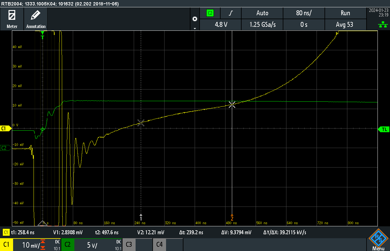
The current handling capability of these inductors is not dictated by the max current the coils of wire can take before getting too hot, but by the max magnetic field the core of the inductor can support. For ferrite core inductors (the most common core type), as current through the inductor increases, the magnetic field increases, and the magnetic domains in the core start to align with the magnetic field of the coil, increasing the energy the inductor can store. Once the current through the inductor increases to the point where all the domains in the core are aligned, the “enhancement” in energy storage caused by the core stops, and the effective inductance of the inductor drops. This can be seen at the elbow of the curve, and operating circuits like switch mode power supplies, or LED drivers above the saturation current will result in lower efficiency and more heating.
PCB Design

After Googling around a bit to get some guidance on measuring inductor saturation current, I ran across this thread, https://www.eevblog.com/forum/projects/inductor-saturation-tester-alternative-route-to-dump-the-excess-energy/ Subsidiary Threads: https://www.eevblog.com/forum/beginners/help-with-testing-inductor-saturation-current/, describing a circuit to do just that. I breadboarded it up, and it worked fairly well, but I decided to get a PCB made to reduce the parasitics of the breadboard. While I breadboarded up the circuit using discrete transistors, along with the Digikey order for my well characterized inductors, I also ordered some DGD0215 MOSFET gate drivers. Since it takes about 2 weeks for the PCBs to get here from China, I drew up the PCB with both the discrete transistor MOSFET driver circuit and the DGD0215 drivers. In the case that I didn’t use the DGD0215 drivers correctly in the circuit, I could fall back to the discrete transistors without having to spin up a new board and wait for the slow boat from China for a new PCB. I also added footprints for extra capacitance to supply the turn-on current surge that I didn’t need, as well as a 12 volt regulator to supply the drivers from a higher voltage for the device under test. In the end I just used 2 bench supplies; one at 12 volts for the MOSFET drivers, and one at 12-20V to test the inductors. I also put in many test points spaced for an oscilloscope probe with a ground spring, to make debugging and measuring easier. Since adding all the extra pads is free, but getting a new board takes 2 weeks, I often try to think of what could go wrong and create alternatives for that situation as well as copious test points into the PCB.

If I were to create a second version of the PCB, I would remove a lot of these extra pads, as well as shortening the current loop which drives the current through the test inductor. The high current loop in this design runs around the outside of the PCB, increasing the parasitic capacitance and inductance, and hence the ringing seen in the traces, as well as increasing the EMI radiated from this device. This PCB was focused on functionality, but it works well enough that I will probably not bother to create a better one.

Circuit Function

The full schematic of the board is in the project gallery, but above is the functional schematic of the populated parts. The test power is connected to J1 and 12V to drive the gates is connected to J2. The Function Generator is fed into J12, and the current is measured by the Oscilloscope probe at J16. The various Test Points are scattered about, but the second channel (green) of the scope is connected to TP1. The set of grounds at the lower right are just the ground holes for the Test Points. The inductor under test is connected to J3 DUT.
The 5V pulse from the function generator drives the DGD0215. The DGD0215 inverts the signal, so that, when the pulse is high, the output is...
Read more »


 Lithium ION
 Yann Guidon / YGDES
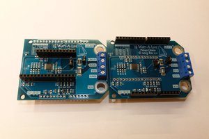
 MagicWolfi
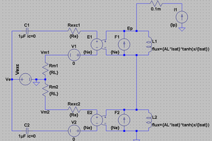
 jbb
jbb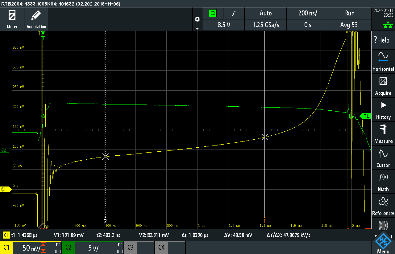