 mircemk
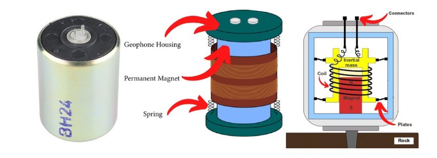
A geophone is a device used in geophysics to detect ground movement. It is specifically designed to measure seismic waves, which are produced by various sources, including earthquakes, and explosions. Typically consist of a mass suspended on a spring and a coil of wire within a magnetic field. When the ground shakes due to seismic activity, the mass moves, causing the coil to move within the magnetic field. This movement induces an electrical voltage in the coil.
This signal is then amplified and filtered, then it is brought to a computer where it is visualized and logged for later analysis with specially designed software for this purpose. Unfortunately, these sensors are mostly unavailable to self-builders due to their high price. This time I will describe to you how to make such a sensor yourself for free from parts that can be found in any workshop.
However, the sensitivity does not lag behind commercial geophones at all. Even this sensor reacts to shocks in all possible directions which makes it incredibly practical, In other words, it replaces many different types of Geophones.
We only need a few components to make it.
- A plastic container, which serves to isolate the sensor from external influences, and it is preferable to be transparent (I use an ordinary plastic box for storing sugar or coffee)
- A small mains transformer taken out of an old electronic device with a power of a few watts
- Neodymium magnet (I use a magnet removed from an old PC hard drive)
- Aluminum or copper plate with a thickness of about 1 mm
- light spring
- and some nuts and bolts as needed

This project is sponsored by PCBWay. They has all the services you need to create your project at the best price, whether is a scool project, or complex professional project. On PCBWay you can share your experiences, or get inspiration for your next project. They also provide completed Surface mount SMT PCB assemblY service at a best price, and ISO9001 quality control. Visit pcbway.com for more services.

This time we will make only the Geophone, and in one of the following videos I will present you the method of making the signal amplifier, filter, as well as the A/D converter, where I will try to do it in the simplest way so that it is closer to a larger number of enthusiasts who potentially would like to make it. I will also describe how to set up a simple 24/7 monitoring software to work with this sensor.

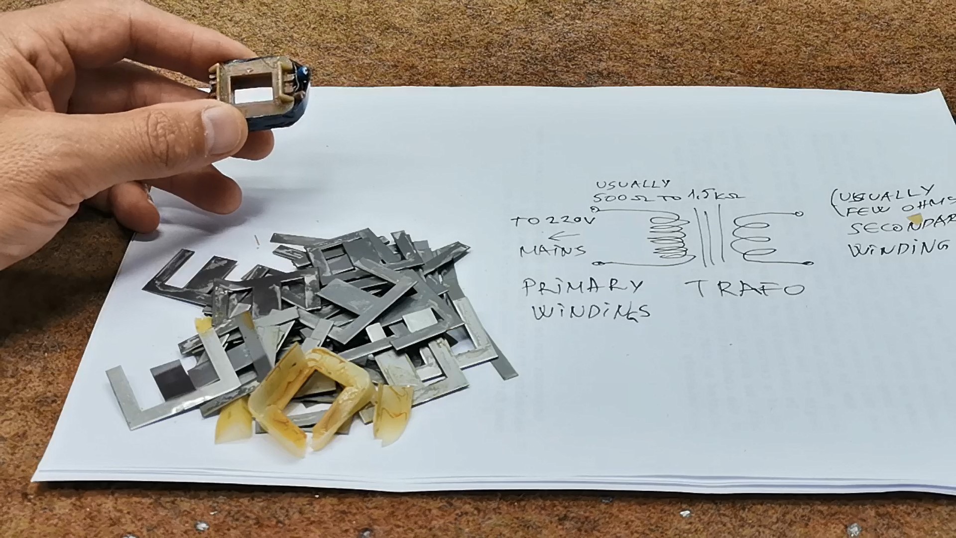
Now let's start making the sensor. First we need to disassemble the transformer, actually separate the windings from the metal part.
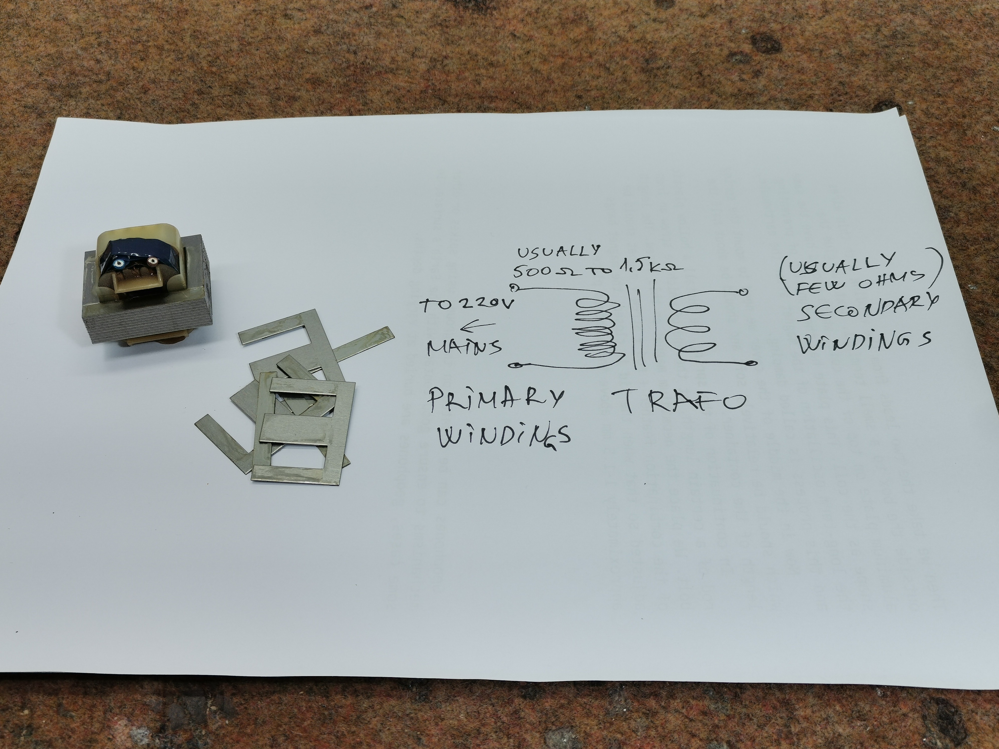
We need the primary winding, which contains a larger number of windings with a thinner wire. If the windings are covered with insulating tape, then with an ohmmeter we look for the winding with the highest resistance. Of course, we can also make this coil by winding 500 to 1500 turns of thin lacquered copper wire with a diameter of 0.1 mm
This winding need to be glued to the bottom of the box. Then we take the two leads from the winding with thin wires outside the box to a small terminal. Next, we glue the aluminum plate on top of the coil, which should have the same shape as the coil. This plate has the function of preventing the long-term oscillation of the magnet after the earthquake, and this process is called damping. When a magnetic field moves through a conductor the movement induces an eddy current in the conductor. The flow of electrons in the conductor immediately creates an opposing magnetic field which results in damping of the magnet.

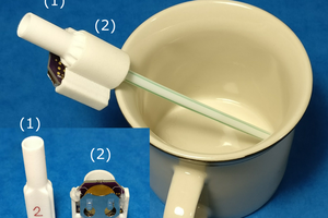
Now in the middle of the cover we need to mount the spring which should be relatively soft and should be about half the length of the container.
In continuation of the spring, we install a hollow plastic rod of a certain length, at the end of which we screw an iron bolt, which serves for precise positioning...
 jflaschberger
 Laio Athos Nevar Fonseca
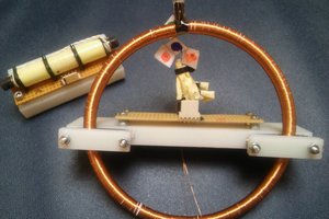
 Aron Molnar
 jaromir.sukuba