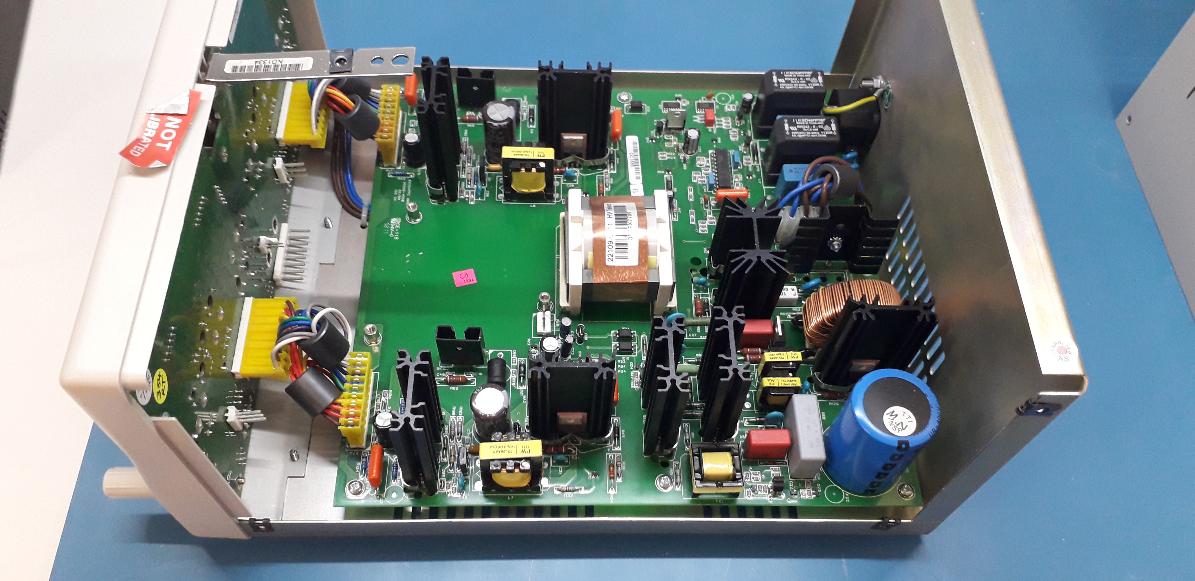
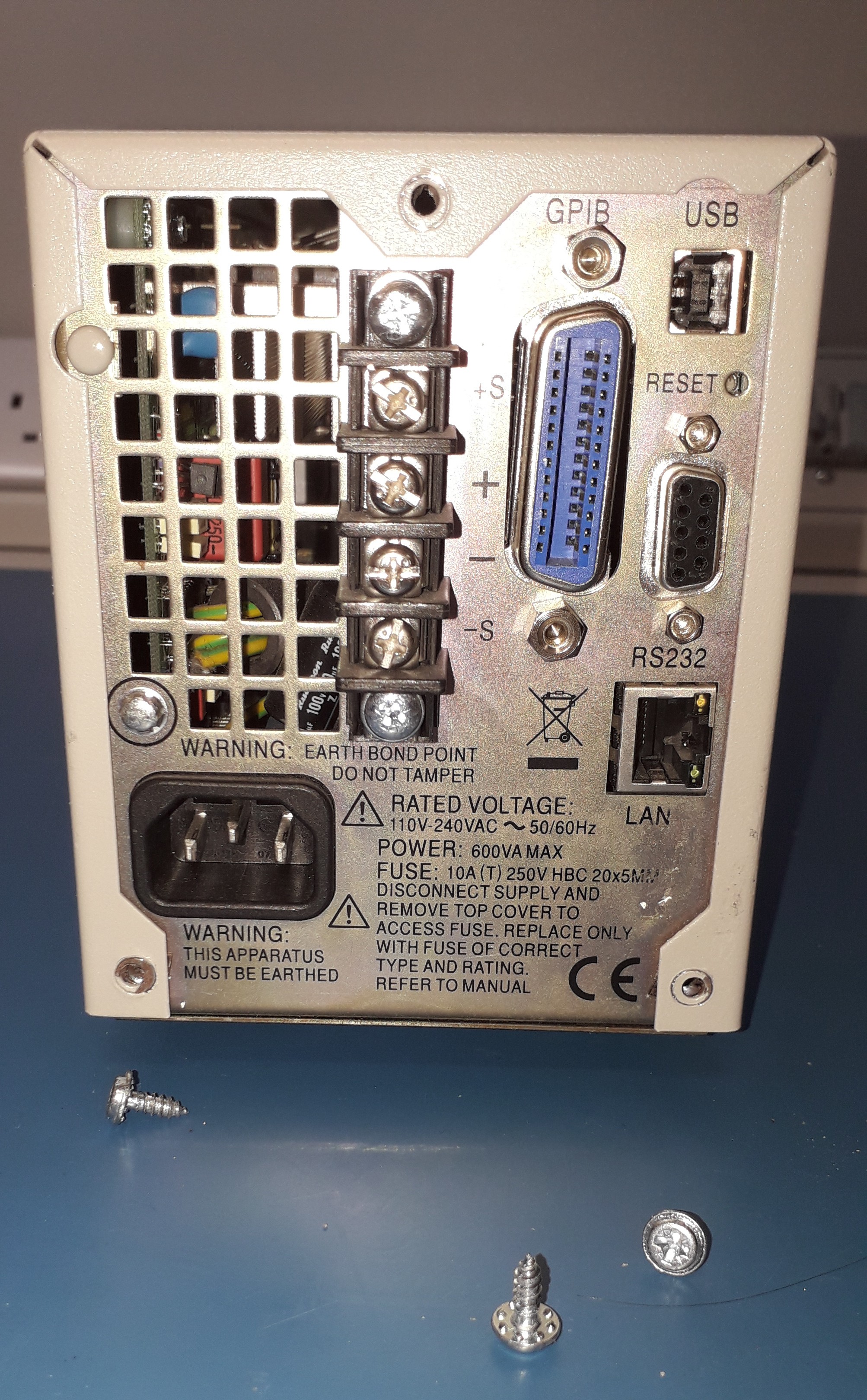
This is a switch-mode PSU, so the mains is rectified to around 400 volts DC inside.
Extra care is required to avoid touching this dangerous part of the PCB.
Fault:
Sparking at back of unit.
Suspected cause:
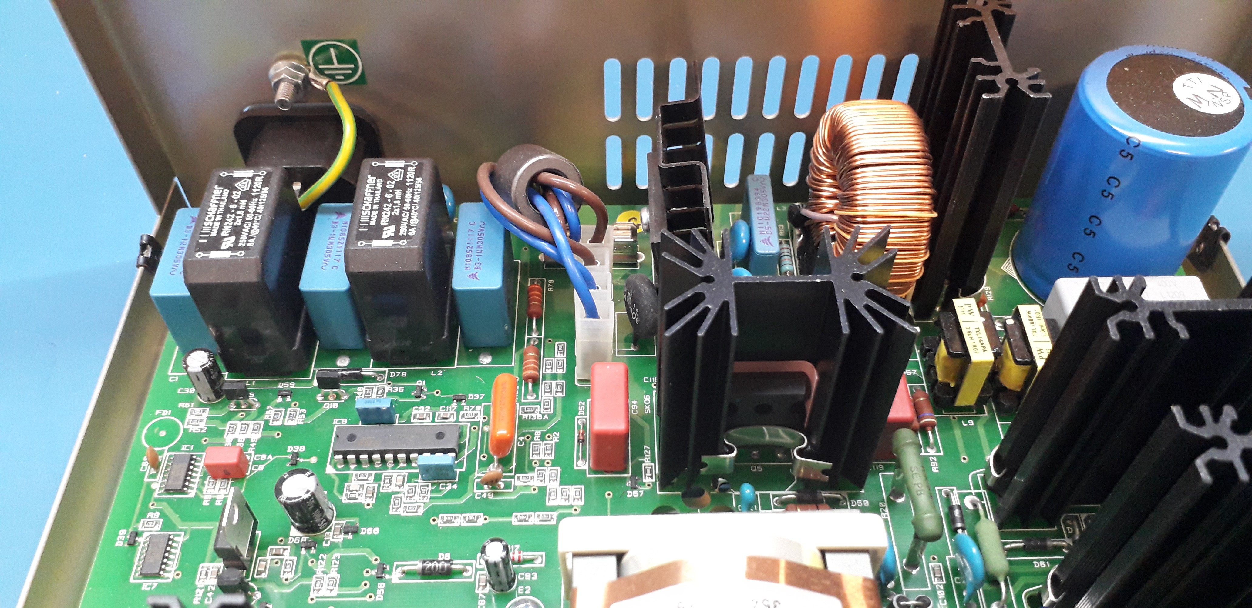
Faulty power connector or EMC capacitors.
Examination:
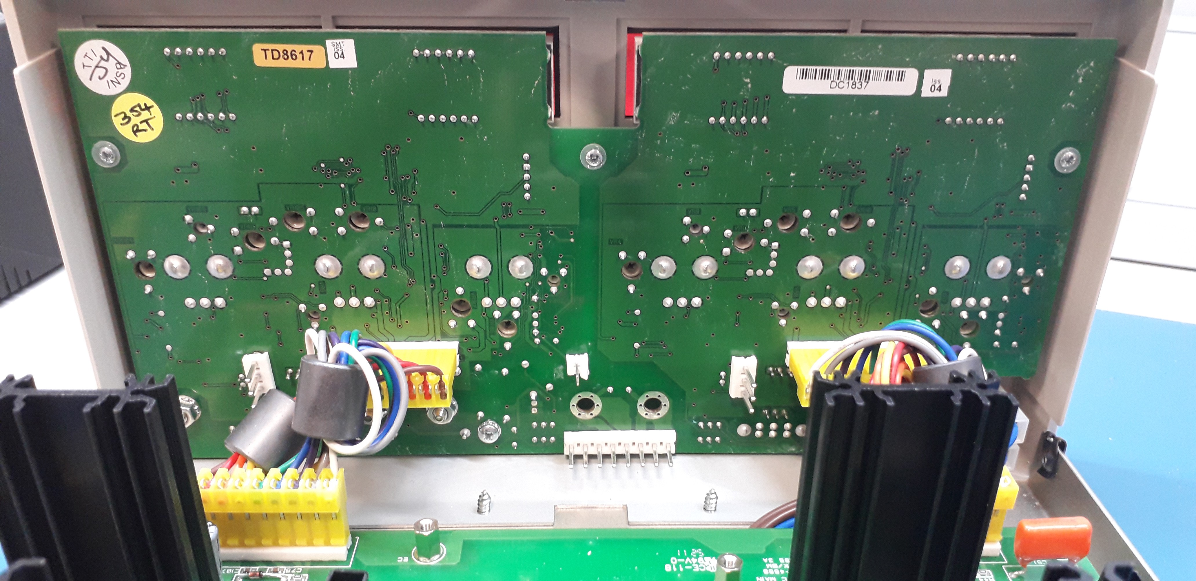
The power inlet was loose in the PCB, because of repeated cable insertions and no attachment to the case. Thus the strain goes direct to the PCB joints.
Switched on, set dials to maximum. Leftt around 28.8V and drifiting, right around 32.88
Dials set to minimum.
Left side very slowly descends to 14.3 volts, terminals are at -0.424 volts.
Right side slowly descends to 1 volts, terminals measures 0.017 volts and quickly rise to 32 volts when dial turned.
Voltage displays take a very long time to change when dials adjusted.
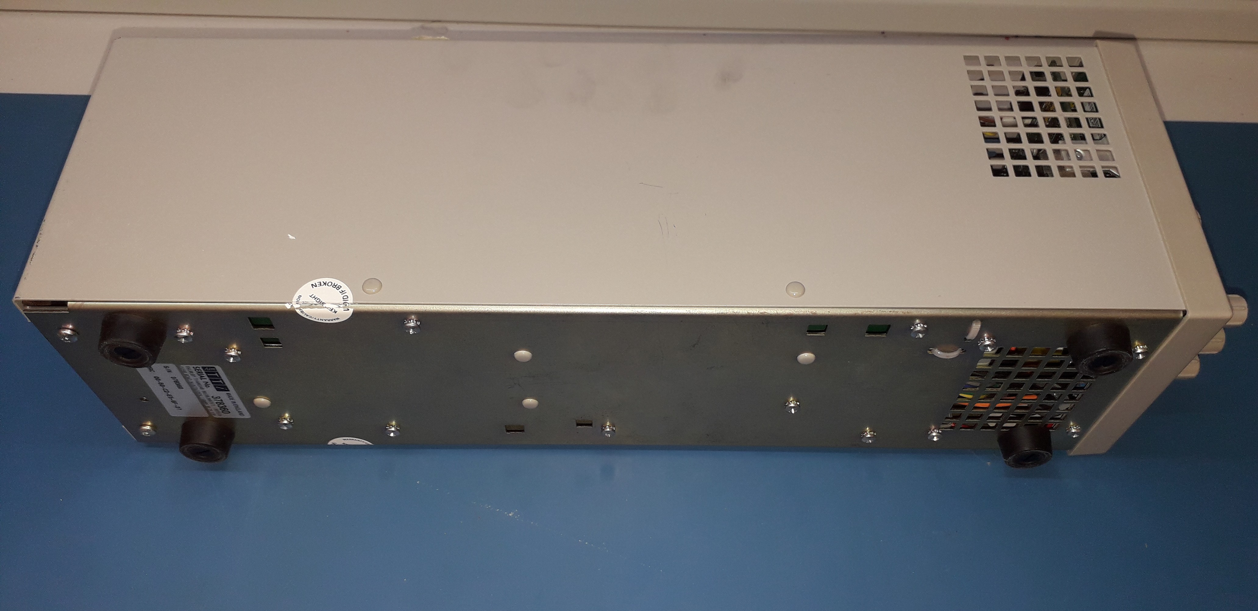
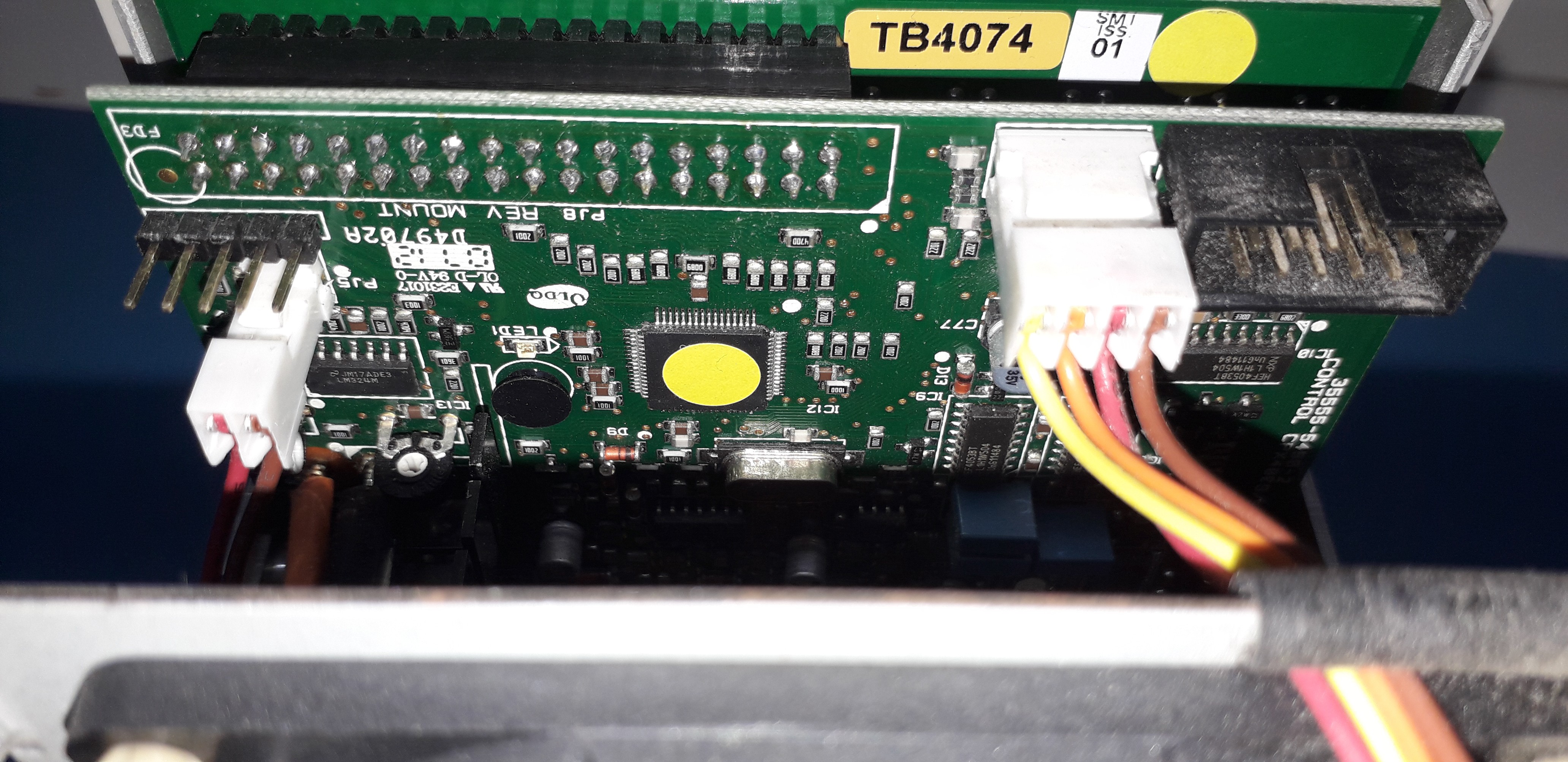
A look inside shows no disconnected cables. It is essentially two power supplies in the same case, with some push-buttons to connect them in parallel, serial, or not at all.
Therefore it seems odd that both sides should be failing at the same time.
 Keith
Keith