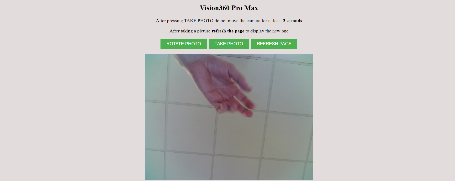
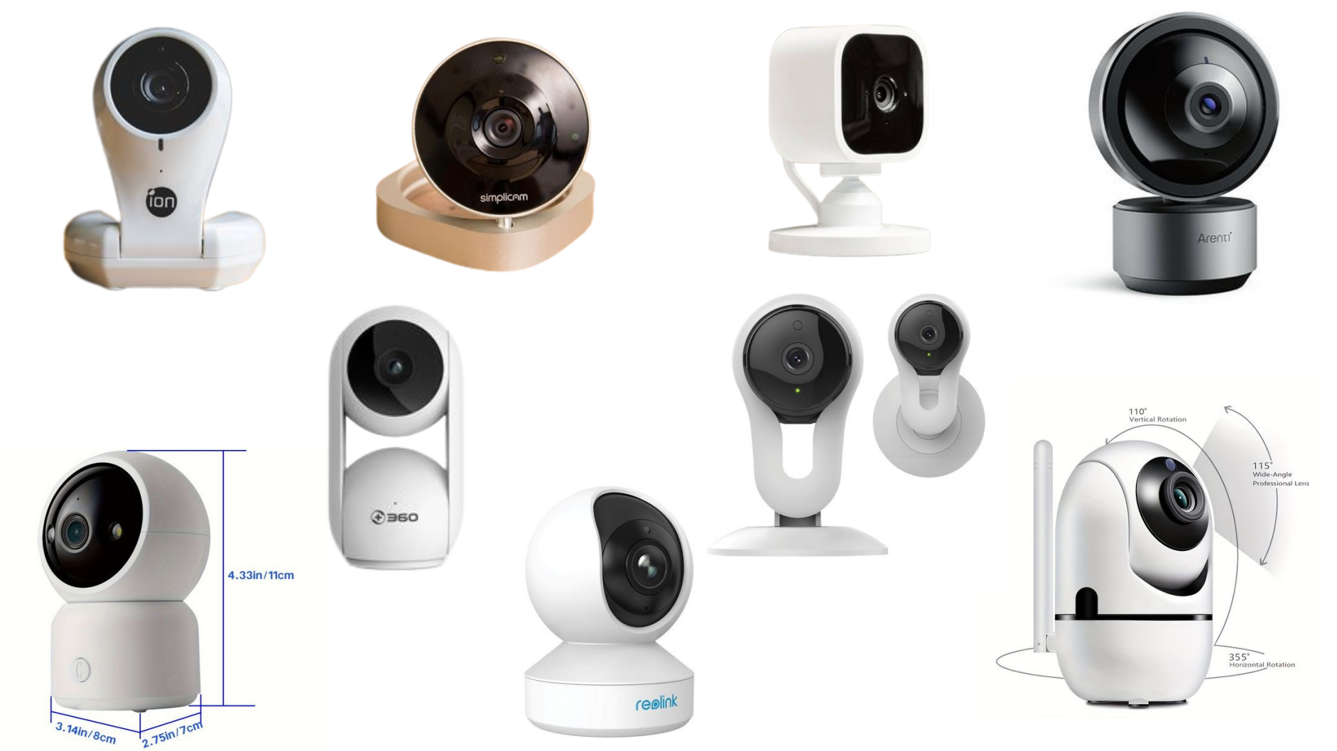
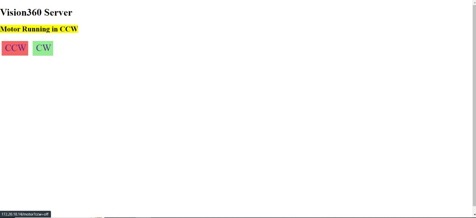
Our project aims to develop a camera capable of connecting via WiFi to a smartphone or computer. This setup allows the user to remotly control the direction the camera is pointing through a web server interface, as well as facilitating other functionalities, such as video streaming or capturing images. Implementing IoT technology to a common product such as a camera, allows users to conveniently control and interact with products seamlessly, enhancing customer-satisfaction.
The advantage of creating our own web server is that it allows for a more customizable experience and a higher degree of control.
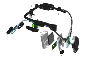
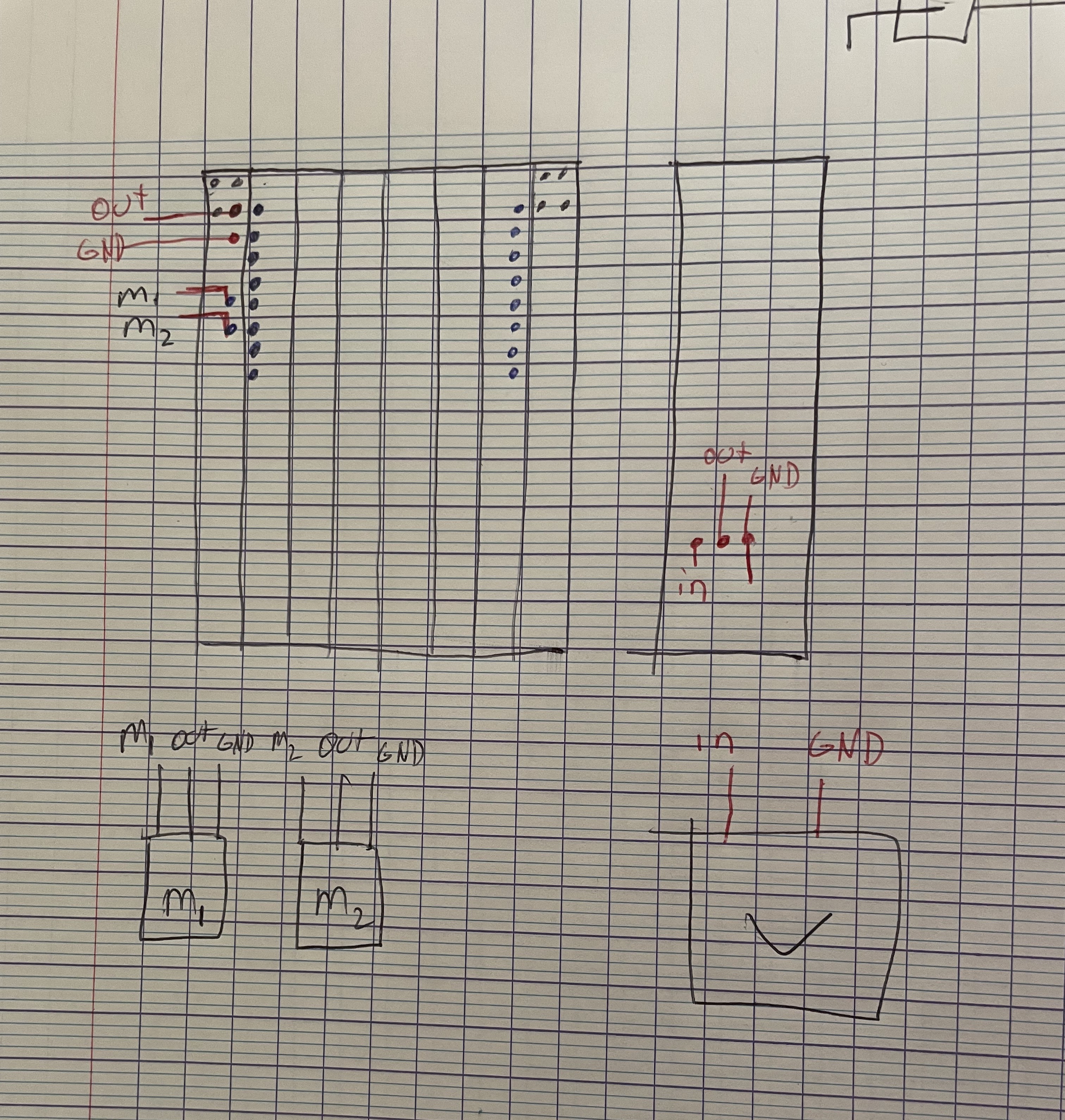
Lastly, below is attached an image that contains the electric diagram of the whole circuit

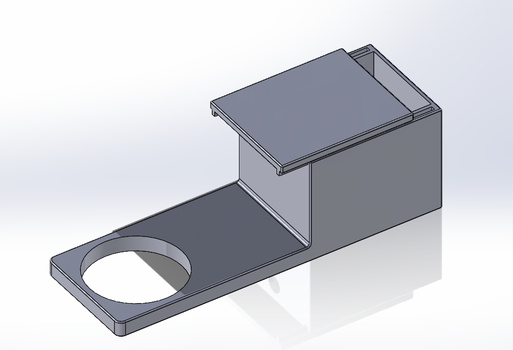
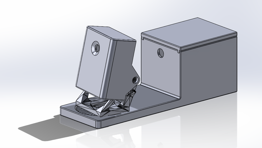
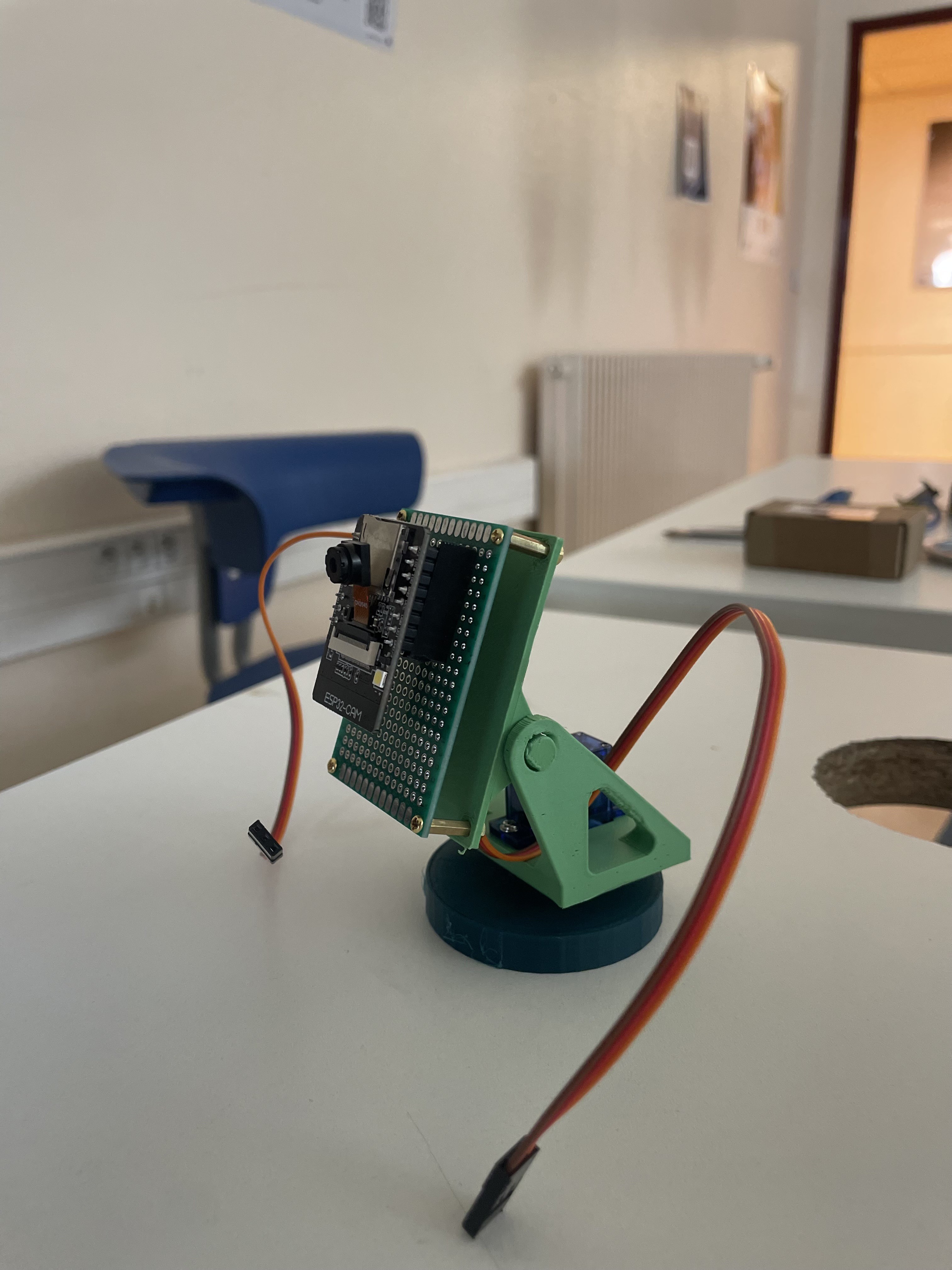
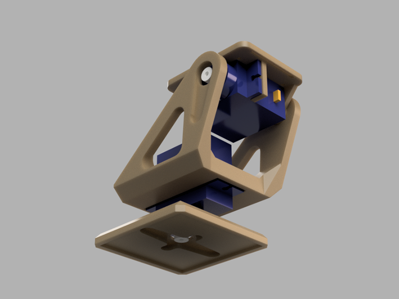
 Renders of the internal structure
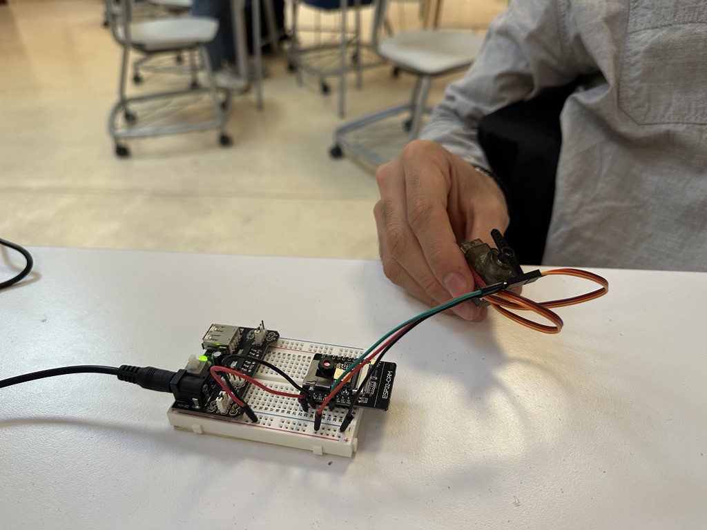
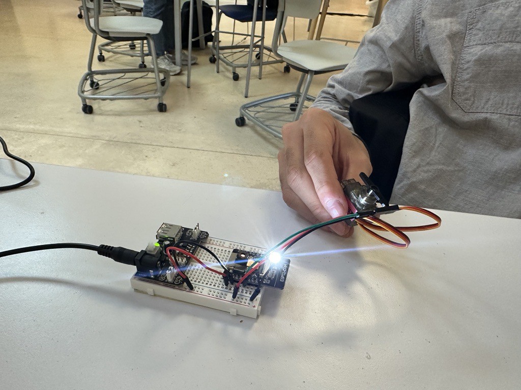
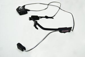
 Testing out the servomotors.
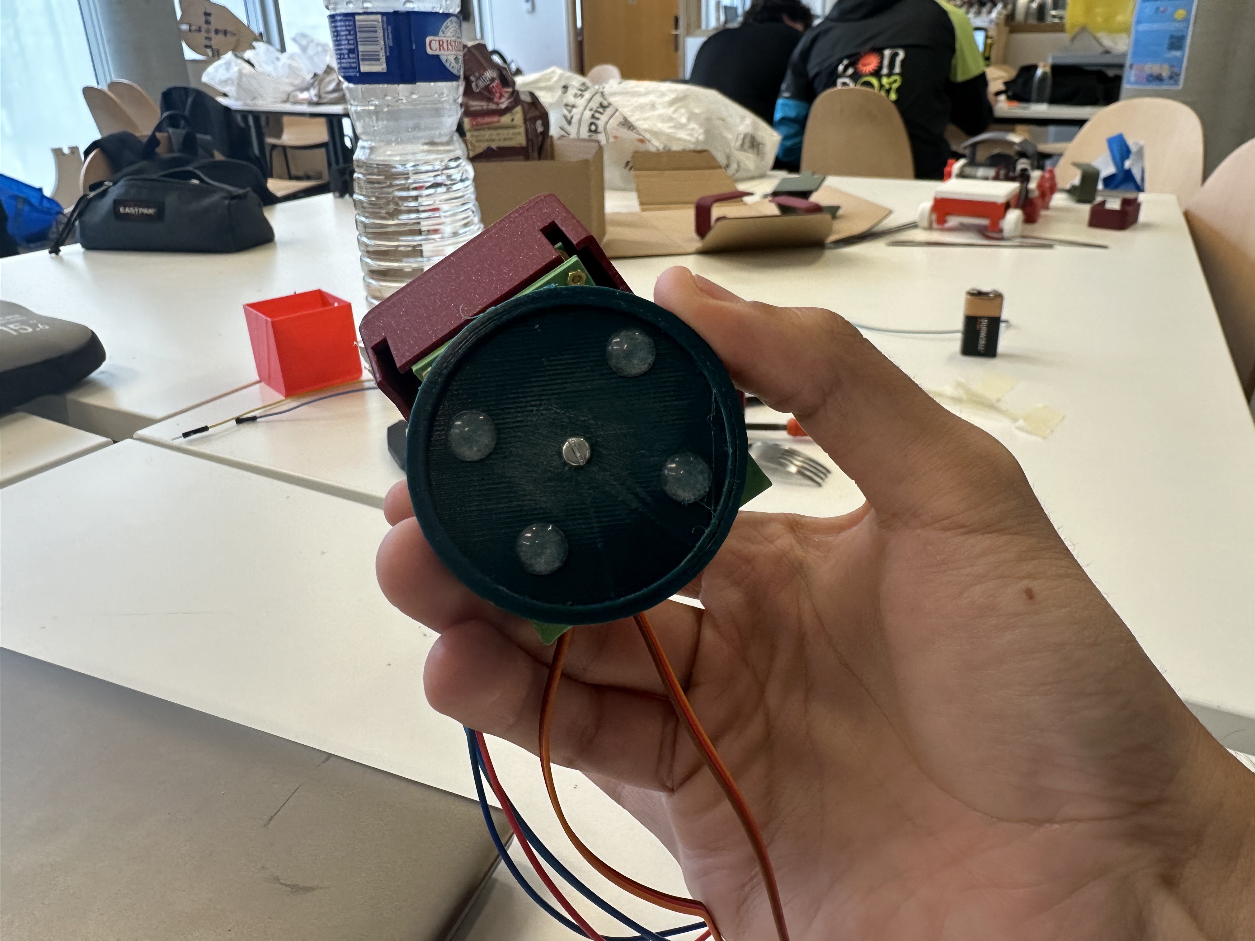
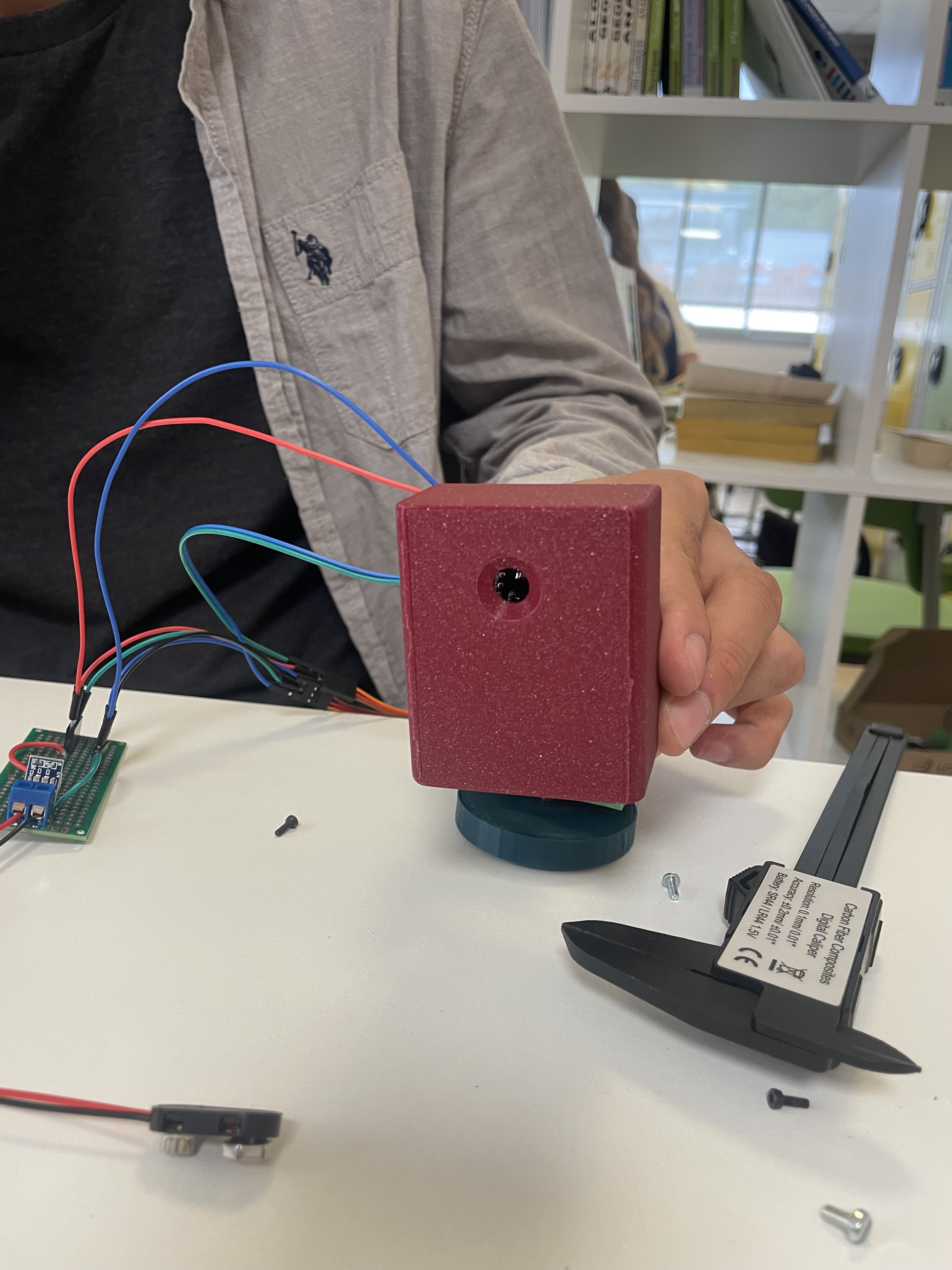
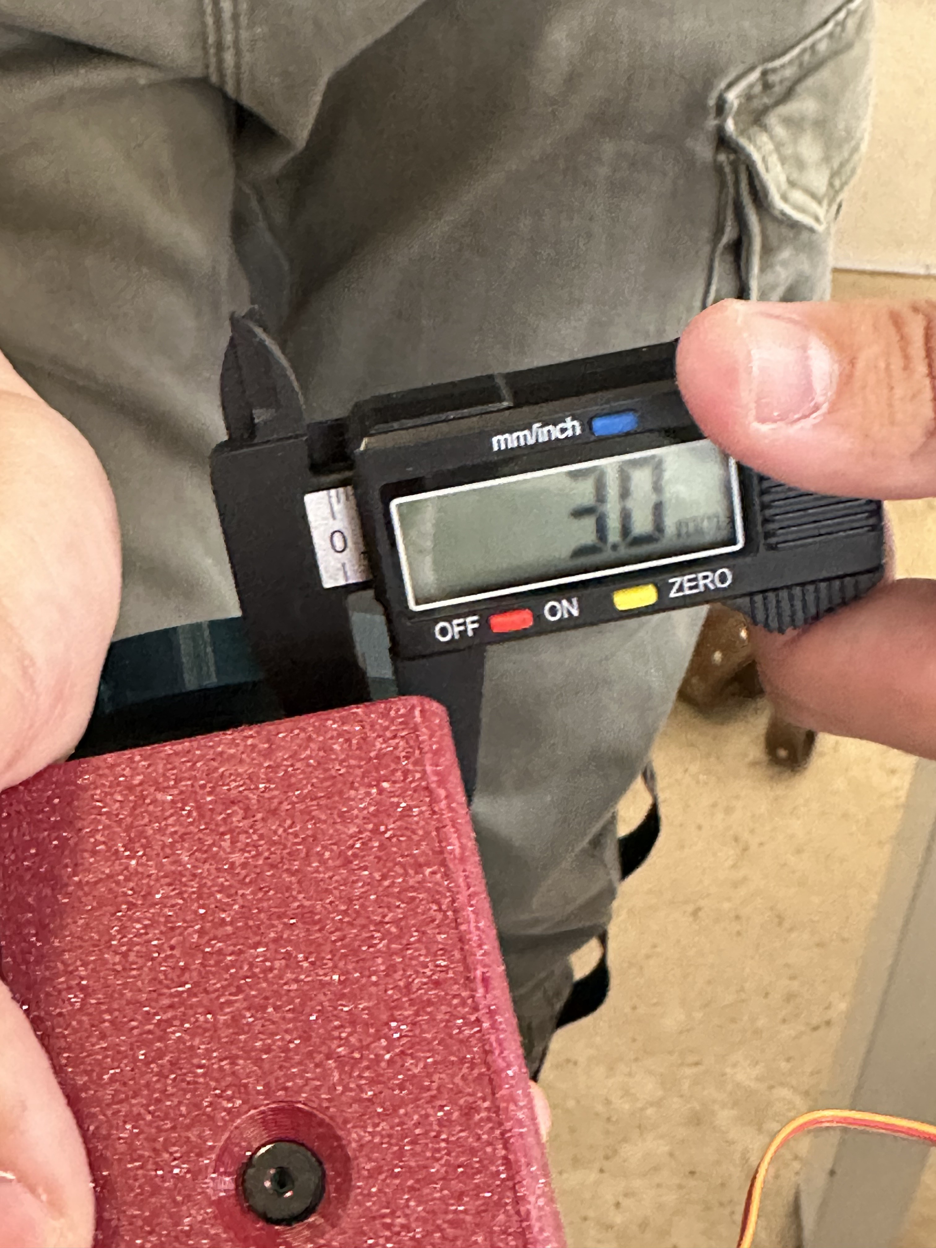
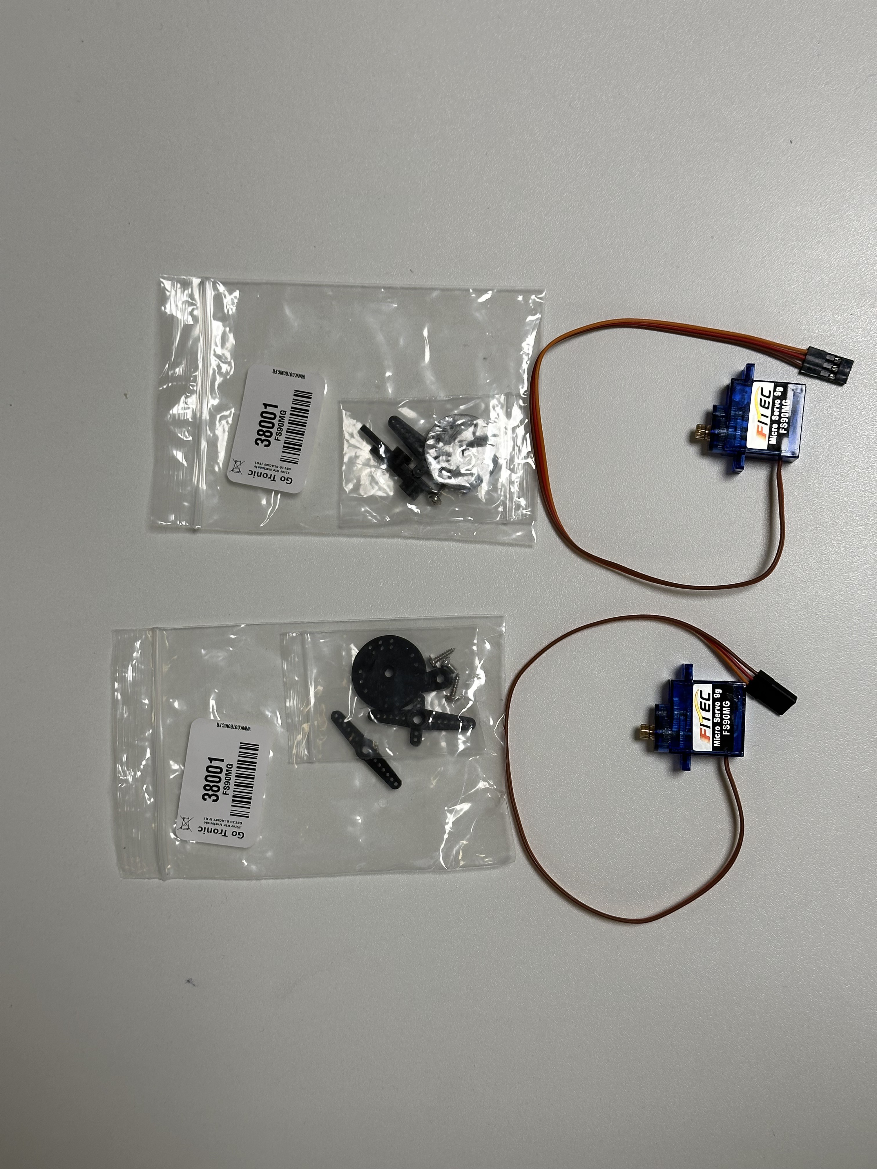 Preparing the material for next session
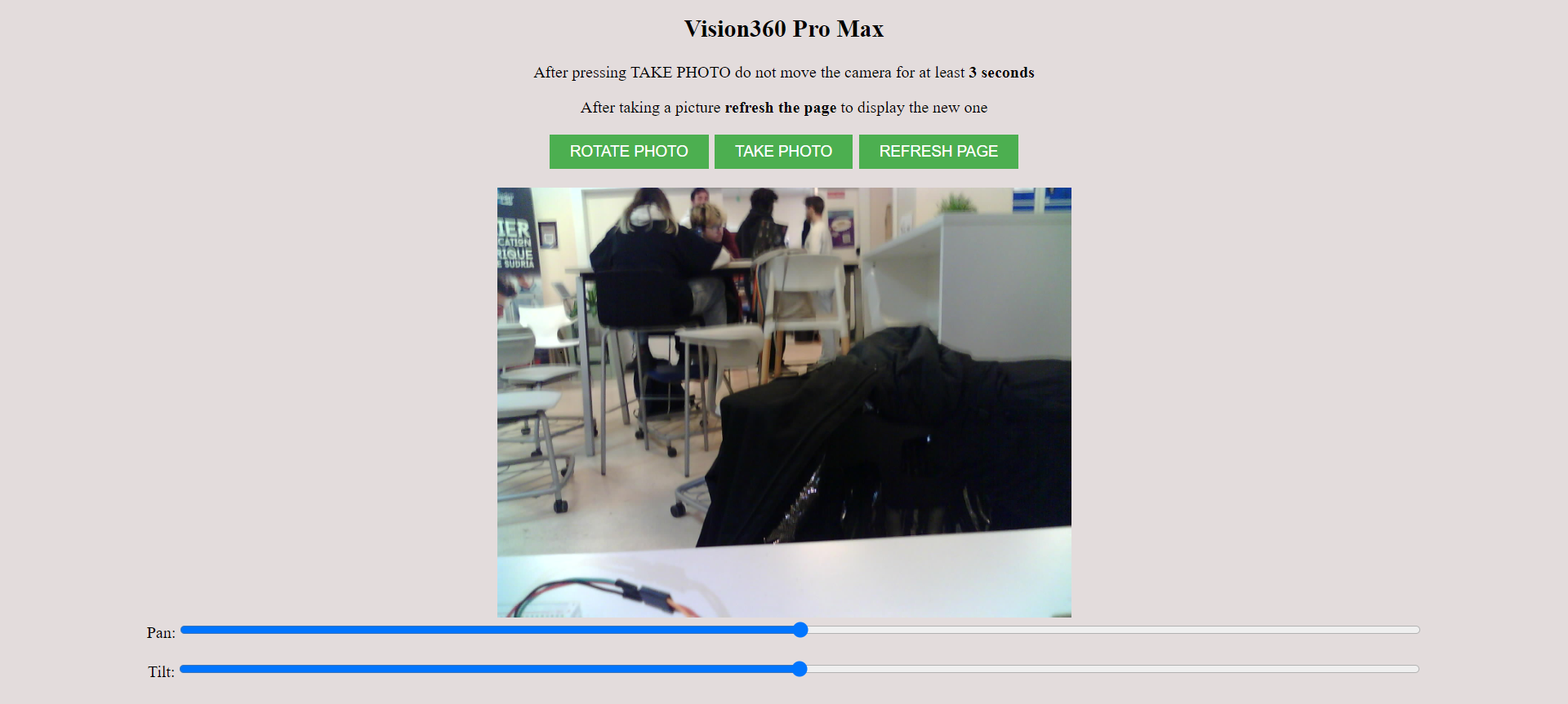
 Makeroni Labs
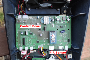
 RemoteMCU
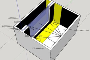
 rdmyldrmr