 gokux
gokuxIn this project, we will build a tiny internet clock connected to your wifi to get time from NTP servers.
Supplies

- Seeed Studio XIAO ESP32C3
- 0.91 Inch 128x32 OLED LCD Display
- USB C cable
- Connecting wires
Step 1: Modeling in Autodesk Fusion 360

I used Fusion 360 for planning and designing this
[upload all design files]
Step 2:3d printing
We also need to 3d print some parts for this project. i printed mine with my Anycubilc Kobra 2 neo 3d printer All files are available at Step 1

Step 3: uploading code to xiao
I always like to upload the code to the microcontroller before assembly. I am using Arduino IDE for flashing the code.
You need to change 2 thing in order to use this code
- Your wifi SSID and Password
- GMT offset
GMT offset is need to mention in second in code for example your GMT offset it +5.30 hrs of you convert it in to second it will be 5.5 x 3600 = 19800 seconds
The code
#ifdef ESP32
#ifdef ESP32

  #include <WiFi.h>

#else

  #include <ESP8266WiFi.h>

#endif

#include <time.h>

#include <SPI.h>

#include <Wire.h>

#include <Adafruit_GFX.h>

#include <Adafruit_SSD1306.h>


Adafruit_SSD1306 display = Adafruit_SSD1306(128, 32, &Wire, -1);

const char* ssid = "SSID";

const char* password = "Password";


int GMTOffset = 19080;  //Replace with your GMT Offset in seconds

int daylightOffset = 0;  // Replace with your daylight savings offset in seconds


void setup() {

Serial.begin(115200);

if(!display.begin(SSD1306_SWITCHCAPVCC, 0x3C)) {

  Serial.println(F("SSD1306 allocation failed"));

  for(;;);

}

  delay(2000);

display.clearDisplay();

display.setTextSize(1);

display.setCursor(0,0);

display.setTextColor(WHITE);

WiFi.begin(ssid, password);

  while (WiFi.status() != WL_CONNECTED) {

    delay(1000);

    Serial.println("Connecting...");

  }

  Serial.println("Connected to Wi-Fi!");

configTime(GMTOffset, daylightOffset, "0.in.pool.ntp.org","time.nist.gov");

}


void loop() {

time_t rawtime = time(nullptr);

struct tm* timeinfo = localtime(&rawtime);

Serial.print("Time: ");

Serial.print(timeinfo->tm_hour);

Serial.print(":");

Serial.print(timeinfo->tm_min);

Serial.print(":");

Serial.println(timeinfo->tm_sec);

display.clearDisplay();

display.setTextSize(3);

display.setTextColor(WHITE);

display.setCursor(0,10);

display.print(timeinfo->tm_hour);

display.print(":");

if( timeinfo->tm_min <10)

display.print("0");

display.print(timeinfo->tm_min);


display.setTextSize(2);

display.setCursor(90,15);

display.print(":");

if( timeinfo->tm_sec <10)

display.print("0");

display.print(timeinfo->tm_sec);

display.display();


delay(1000);


}
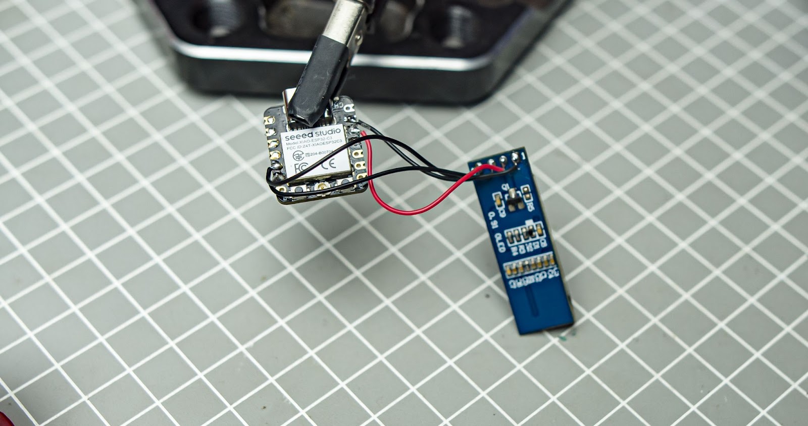
Step 4: wiring diagram
This is the wiring diagram

Step 5: assembly and wiring
Step 1
Connect all 4 wires between OLED and Xiao
Step 2
Glue the oled into the font panel

Step 3
Stick the antenna on the top of the 3d print

Step 4
Place the xiao into the 3d print make sure the USB port is visible on the back glue it with a glue gun. Also connect the antenna into the board


Step 5
Close the front cover by glueing it

test
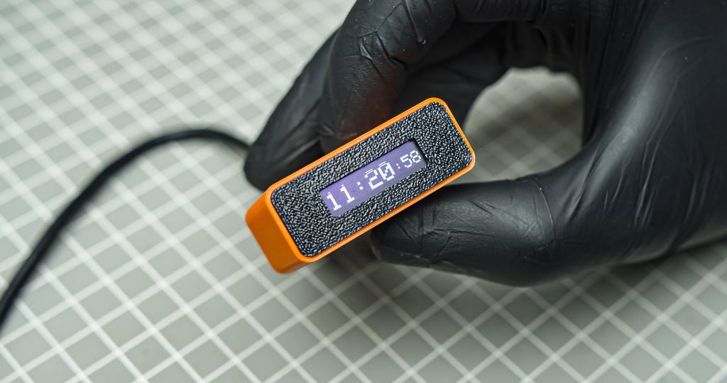
Please connect the USB cable to power the device, which will automatically update the time.


 Jonathas Barbosa
 Junior
 Debinix
 amr.mostaafaa
great idea