 Andy Geppert
I've had this idea in mind for a while and the Hackaday Business Card Contest is the perfect motivation to bring this idea to life. I'm in a frantic scramble to finish the design and get a board running before the close of the contest!
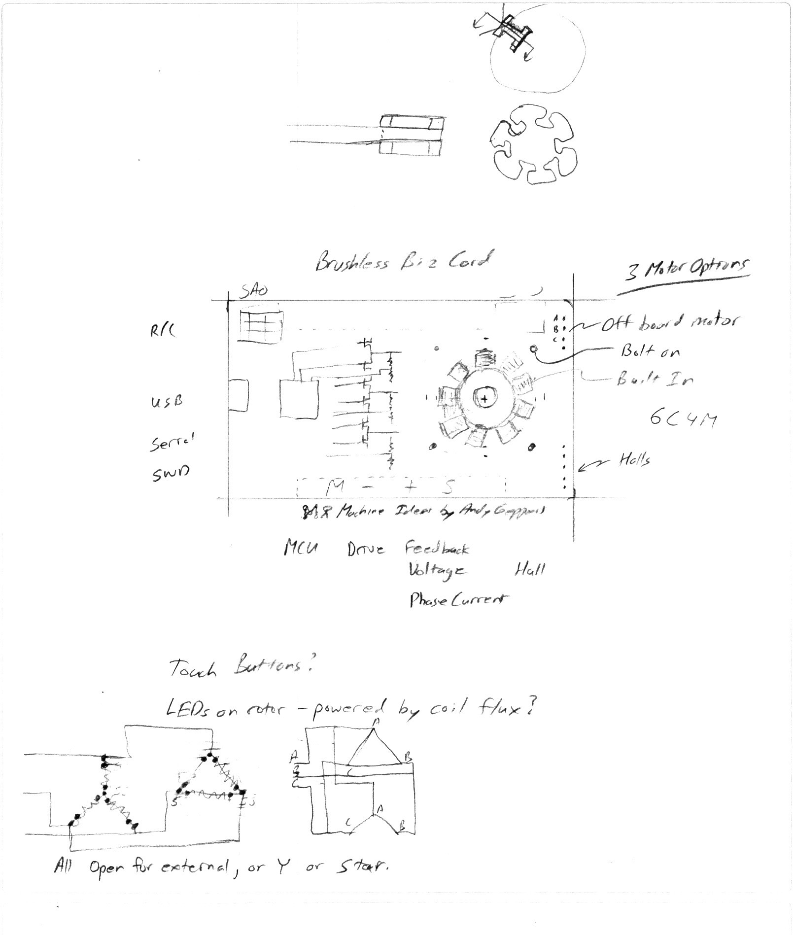
Features
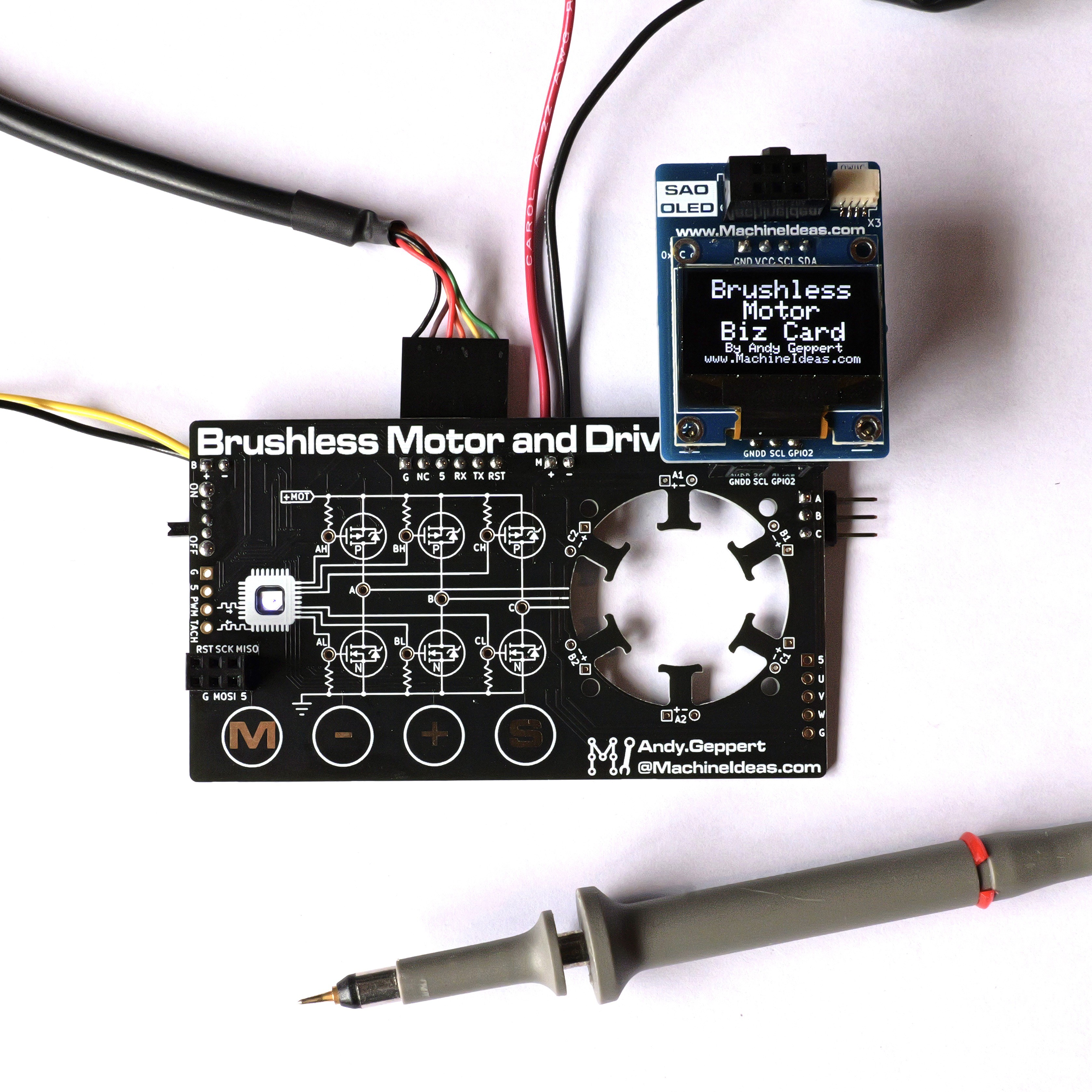
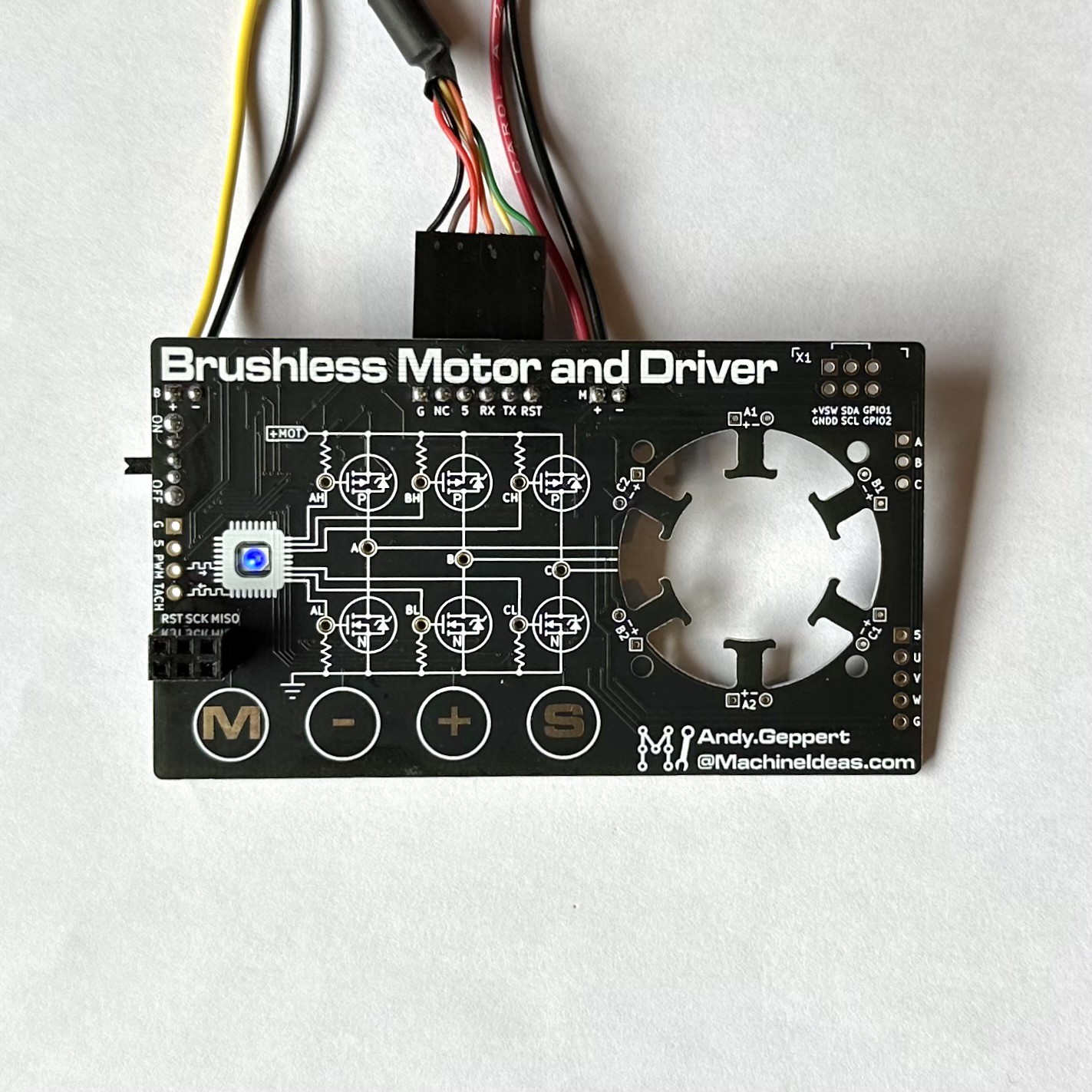
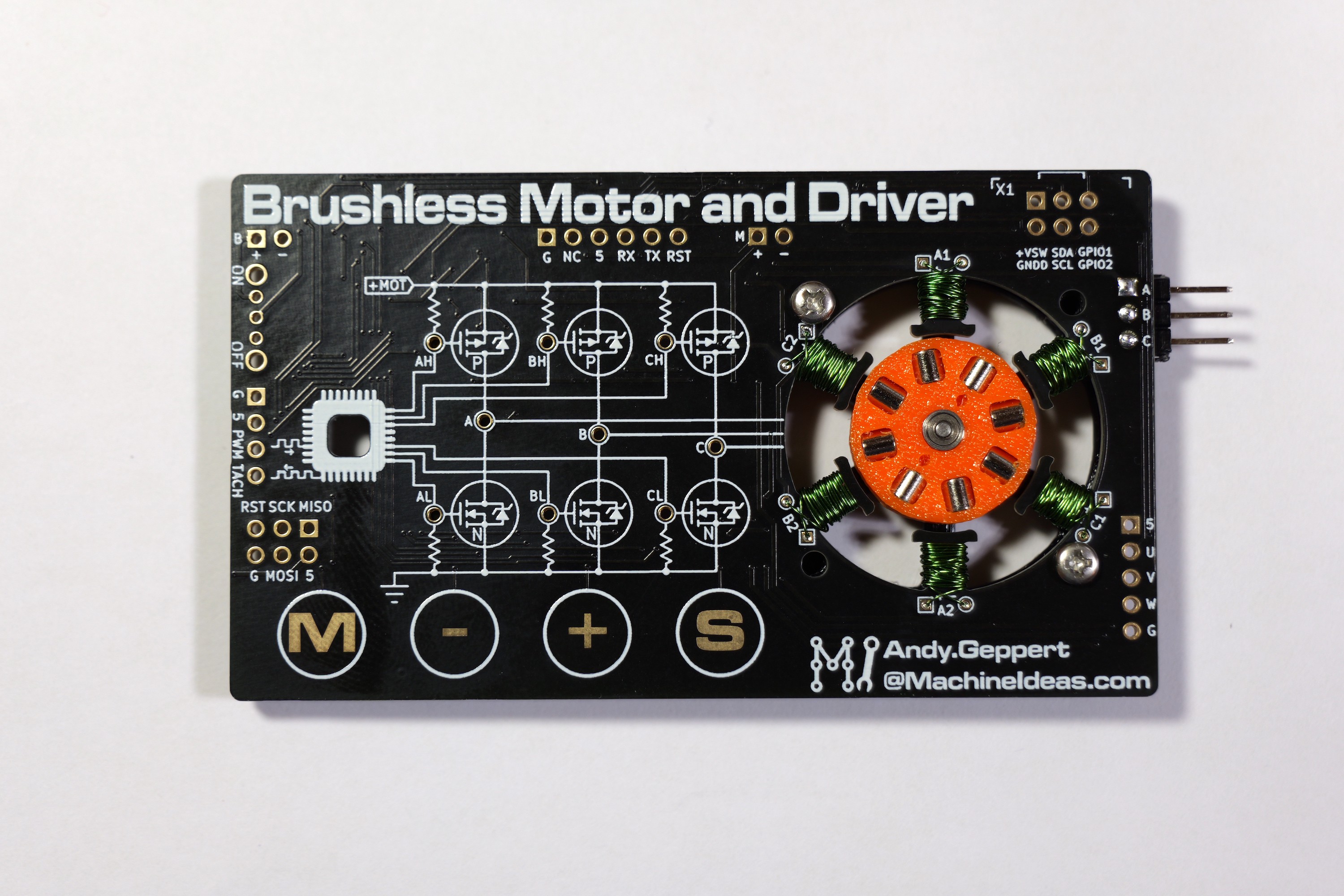
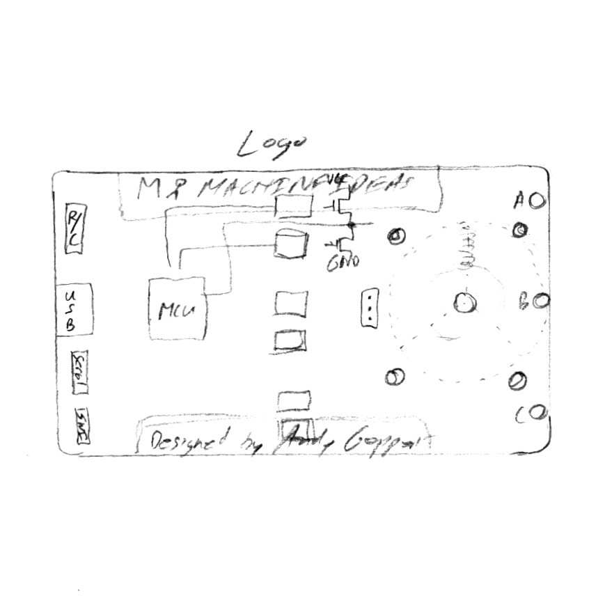
- Built-in schematic with illustrated test points
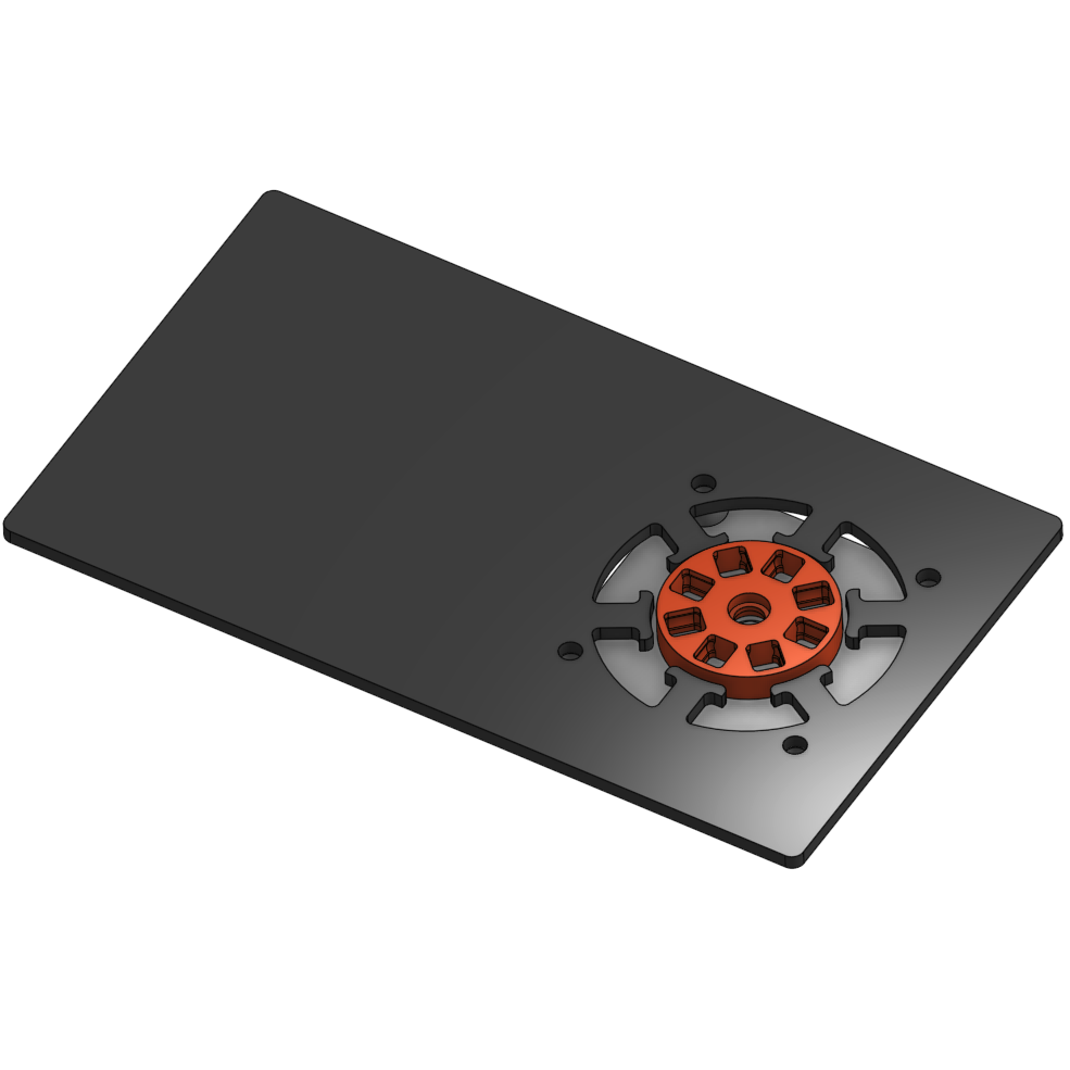
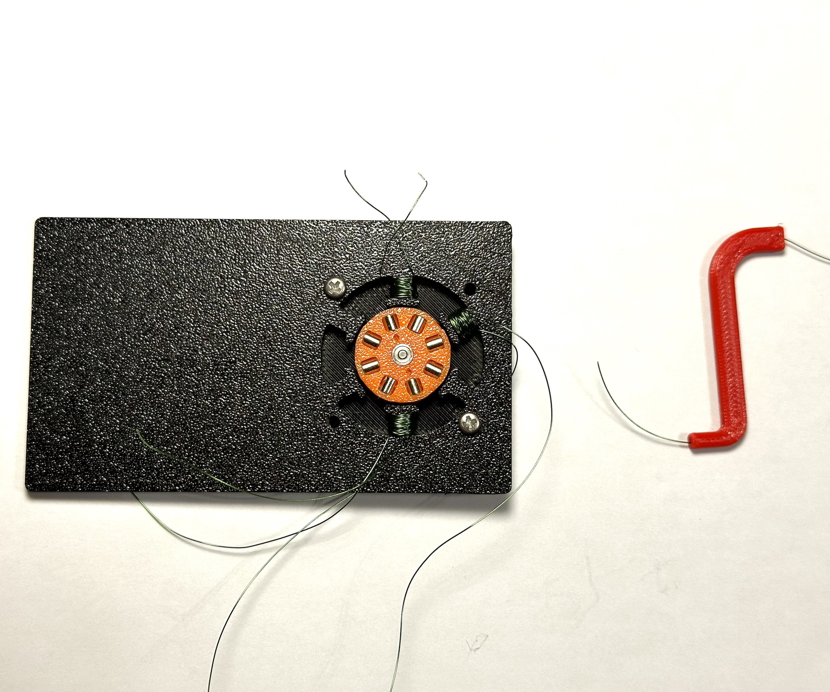
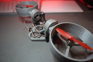
- Built-in motor with option to connect external motor and hall sensors
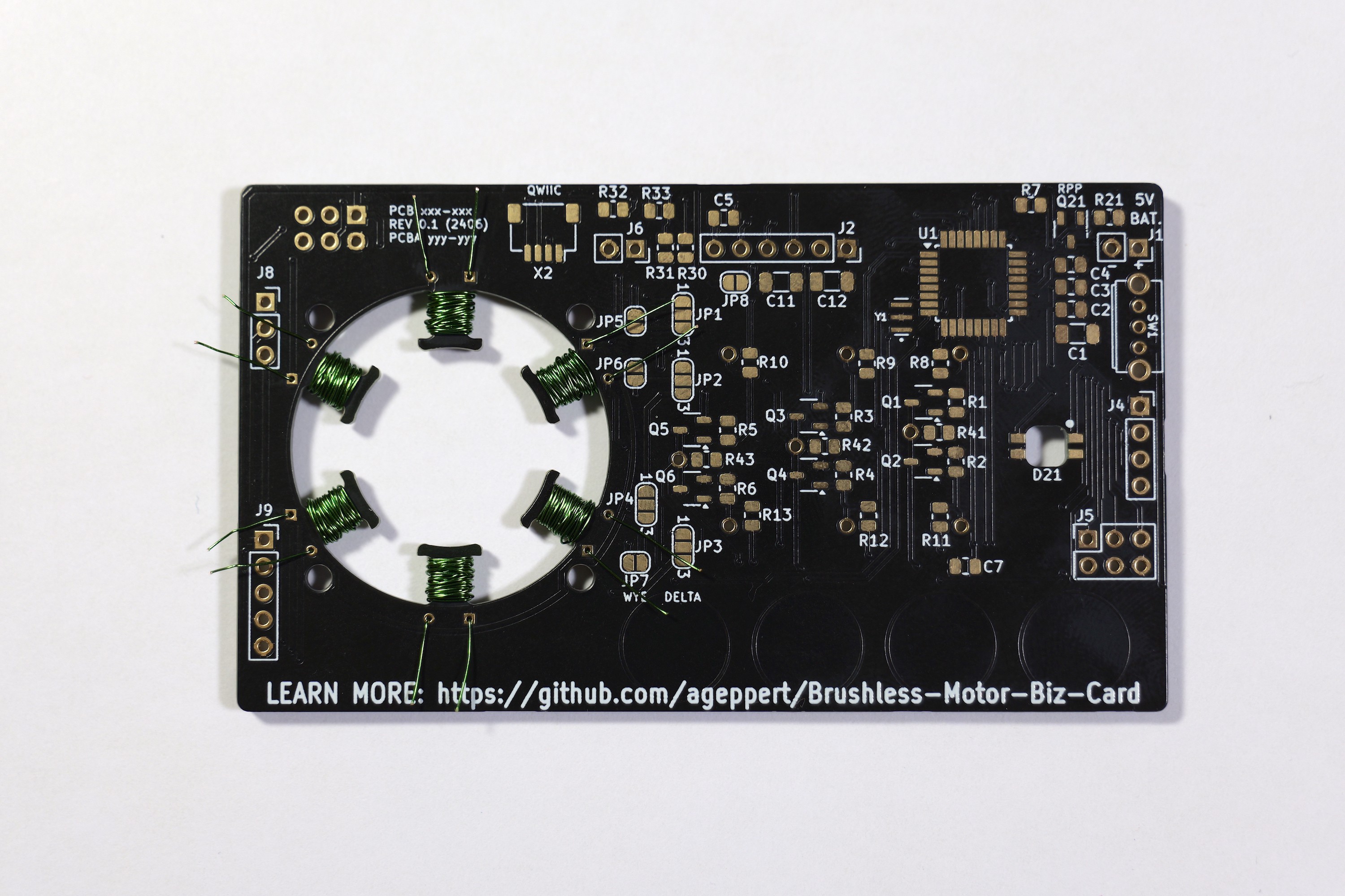
- Adjustable winding configurations via solder jumpers
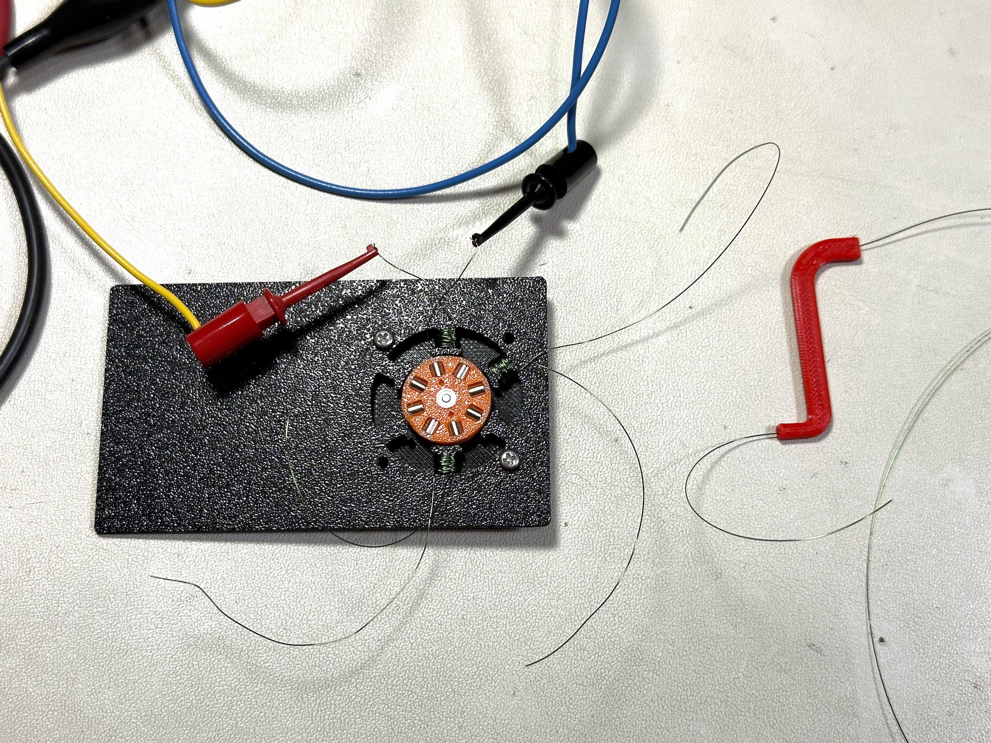
- Simplified voltage feedback from the motor phases for position (using 328PB analog comparators with interrupt feature)
- Optional connections to external motor and hall sensors
- ATmega328PB - Arduino bootloader (via USB-FTDI cable)
- Capacitive touch buttons (Mode, -, +, Select) to control mode, speed, and who-knows-what?
- RGB User LED
- QWIIC/Stemma I2C port
- R/C connector input with tach output
- ISP port
- Power switch to select USB or battery power source
- SAO port for an SAO OLED, of course!
- Simple Arduino code for you to learn and expand upon
I've been inspired and learned a lot from these folks which I'm applying in this project:
- https://www.youtube.com/@CarlBugeja
- https://www.youtube.com/@ELECTRONOOBS
- https://www.youtube.com/@juanpablocanguro
- https://www.youtube.com/@atomic14
- https://www.youtube.com/@PhilsLab
Check out this playlist to learn more about brushless motors and controllers: https://www.youtube.com/playlist?list=PLgr0YZUR4CSVKWWj0__yitdxPeQSaBse1
This project has come to life in a hurry and is not optimized. These are some forward looking features I'd like to incorporate in a future revision:
- Voltage regulator (5V) to allow 4x "AAA" or 1S LiPo power options
- USB C port and built-in USB to Serial conversion, maybe a different MCU solution all-in-one
- More LEDs to visually indicate which transistors are active, and coil polarity
- Built-in single row header to easily connect to scope/logic analyzer such as Analog Discovery
- A hall sensor (or a three) built-in to the PCB for feedback capability
- More complete analog feedback capability
- The rotor is easy to swap out with other pole counts, but other than the wye/delta configurations jumpers for the windings, they are not easy to change. Perhaps the windings could be a separate and removable PCB to enable experimenting with different windings all together?
I'd like to know your feedback and questions in the comments below!
 Saul
Saul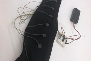
 Peter Walsh
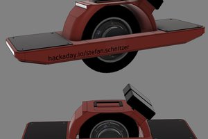
 stefan.schnitzer
 Scott Duckworth
https://marykayintouch.cloud/ wonderful post; continue your fascinating effort.