As I gave to someone the first version of the PolaPi, I had to rebuild it. This time I tried to simplify a bit the process, the printer hack is not needed anymore. Please find below some explanations about some hardware choices and the software.
Hardware
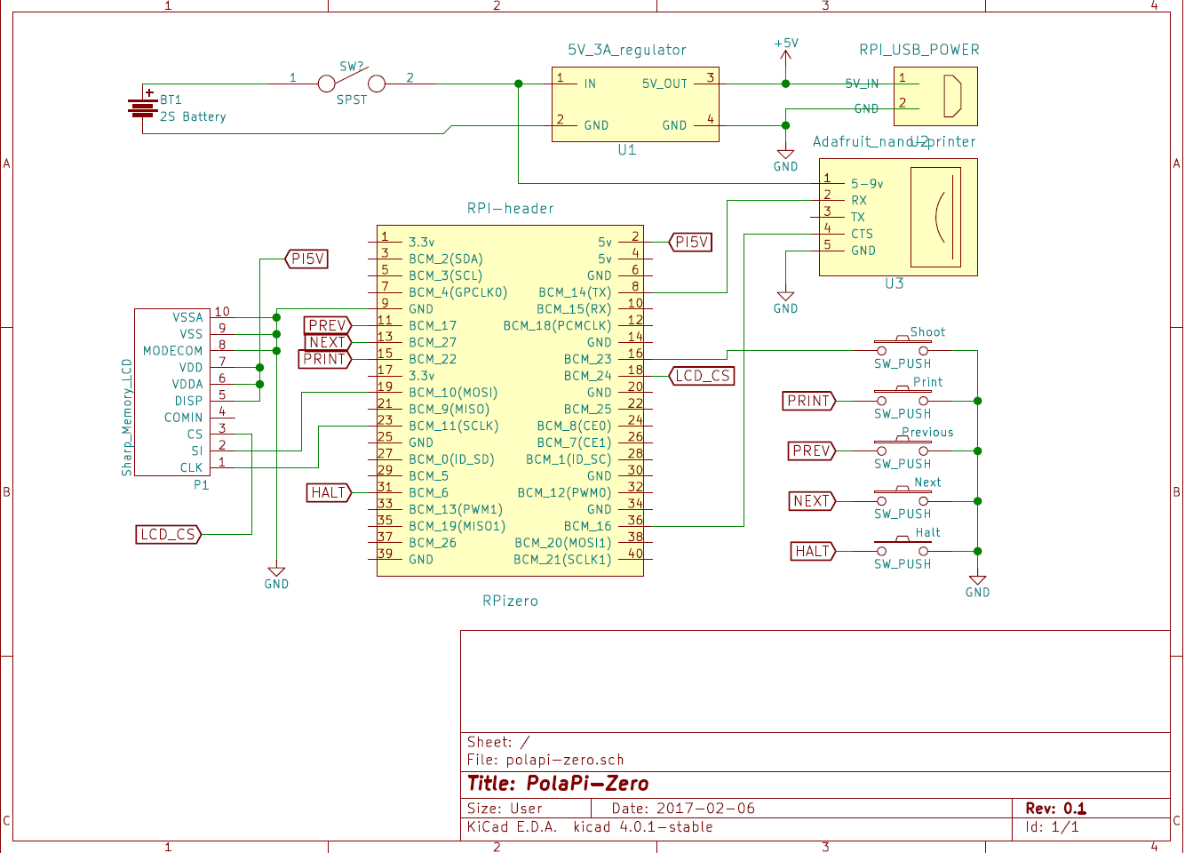
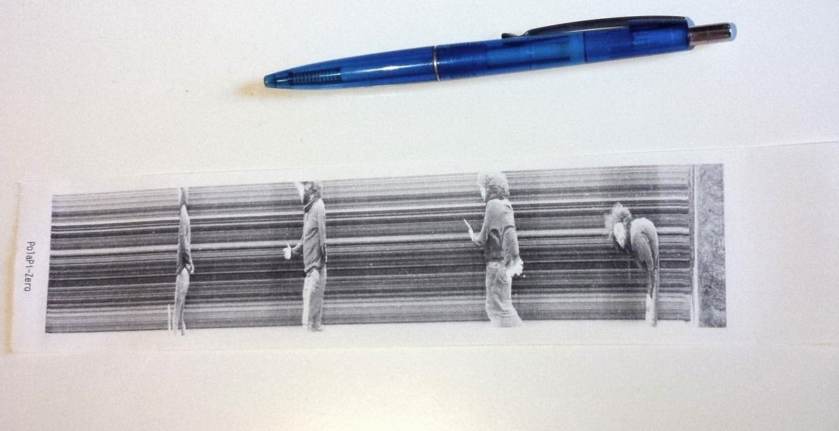
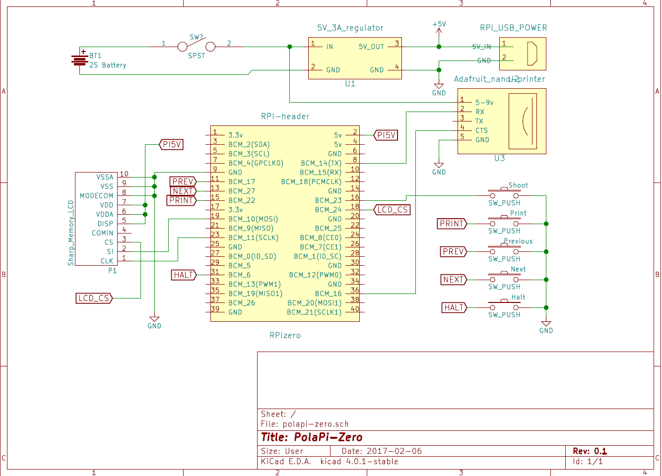
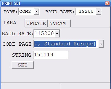
First of all, the pinter. The Adafruit nano printer, despite it's smaller than the regular one, it has a serial CTS pin. This means we can prevent the internal buffer overrun. However I still used the small windows program to increase the serial speed from 9600 bauds to 115200.
The little Sharp memory-LCD is perfectly visible on sunlight, and as the printer do, displays only black or white pixel. It needs a small SMD FFC-10P 0.5mm adapter and connector. It uses SPI but with an inverted logic for the chip select, that's why another GPIO is used.
I oversized the powering I suppose, but the printer can take quite a lot of current. Mainly because I recycled the parts, I used a 3A 5V regulator and a 2S lipo battery. For the moment I use a separate specialized balance charger.
The switch I had to turn it on and off has a little led inside. I reused it in place of the activity led of the raspberry pi zero. The on board led is de-soldered and rewired to the swith one.
Software
This project is a good excuse to start learning Python (finally). It is more popular than Java and a lot of work is already done. The code I made so far, not really the most elegant and explain a bit later, is available on this Github. (polapizero_04.py is the main for the moment) If you manage to re-build the same hardware, I've put a 2GB SDcard image for the raspberry-pi zero on dropbox here.
For the LCD, I'm not enough experienced in C/linux drivers to write a FBTFT module. Then I used the work done by wrobell and his Python library dedicated to the LS027B7DH01. That's why for the moment the screen refresh rate is limited to 8fps. The library allows to set directly a PIL image on the display. I was a bit puzzled about how to build the lib. autotools/autoconf is used and gave some errors at first.
For the printer, Adafruit made a nice library which can handle directly images. In my case I just had to adjust it a bit to let the hardware manage the CTS line and then remove the delays anticipating the buffer filling.
The raspberry pi serial has to be setup as well to manage the CTS line. Here mholling explained everything on his github repository. However the command lines have to be launched reach boot, then added to rc.local
The raspberry pi camera has its nice python library, which is really fast and expose a lot of settings. To avoid as much as possible the latency between the button press and the picture recording, I used two threads each using a splitter port.
The case
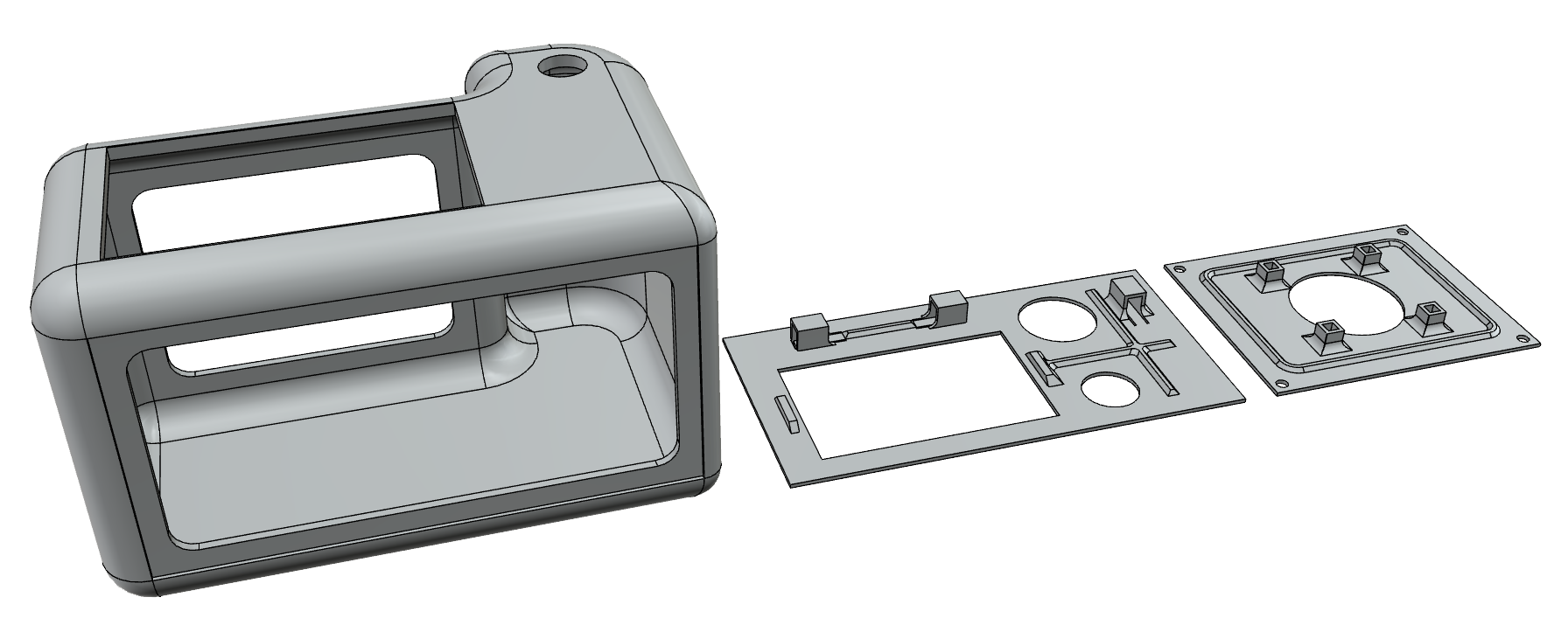
This time I tried to get something a bit better for the case. I spent a bit of time on the autodesk 123D design software and used the www.3dhubs.com services. I'm quite happy with the result, and the hub was very fast.
The 123d file is on github, polapizero013.123dx, as well as .STL files.
[to be continued]
 Muth
Muth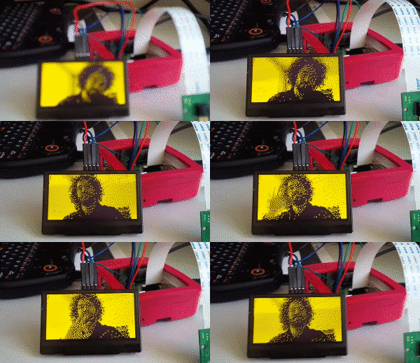




 [
[

 Cameron
 jimmy.c.alzen
 Brenda Armour
hey its a realy cool project ps: i am gona make it
but quick question what sort of buttons did use for all the buttons?
and the power switch?
and why dont u connect the screen with the hdmi port thats on the pi zero?