 Kirschner Christoph
In the summer, when we go to our lake, we have the problem, that we run out of energy often already on the second day. To solve this problem the easiest way would be, that we simply use a normal sun-panel. But as an maker this would also be the most boring way i could imagine. So i thought about how to improve the efficency of the panel and i had the idea to build a sun-tracking sun-panel. And that's what i will do in this project.
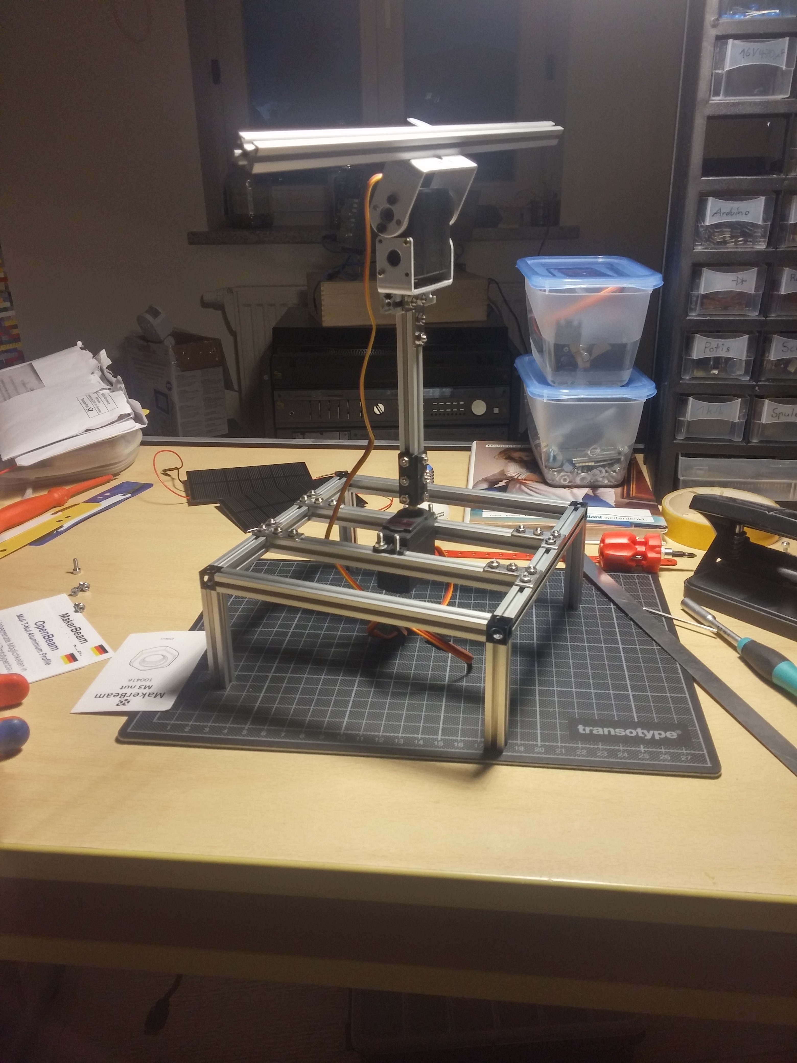
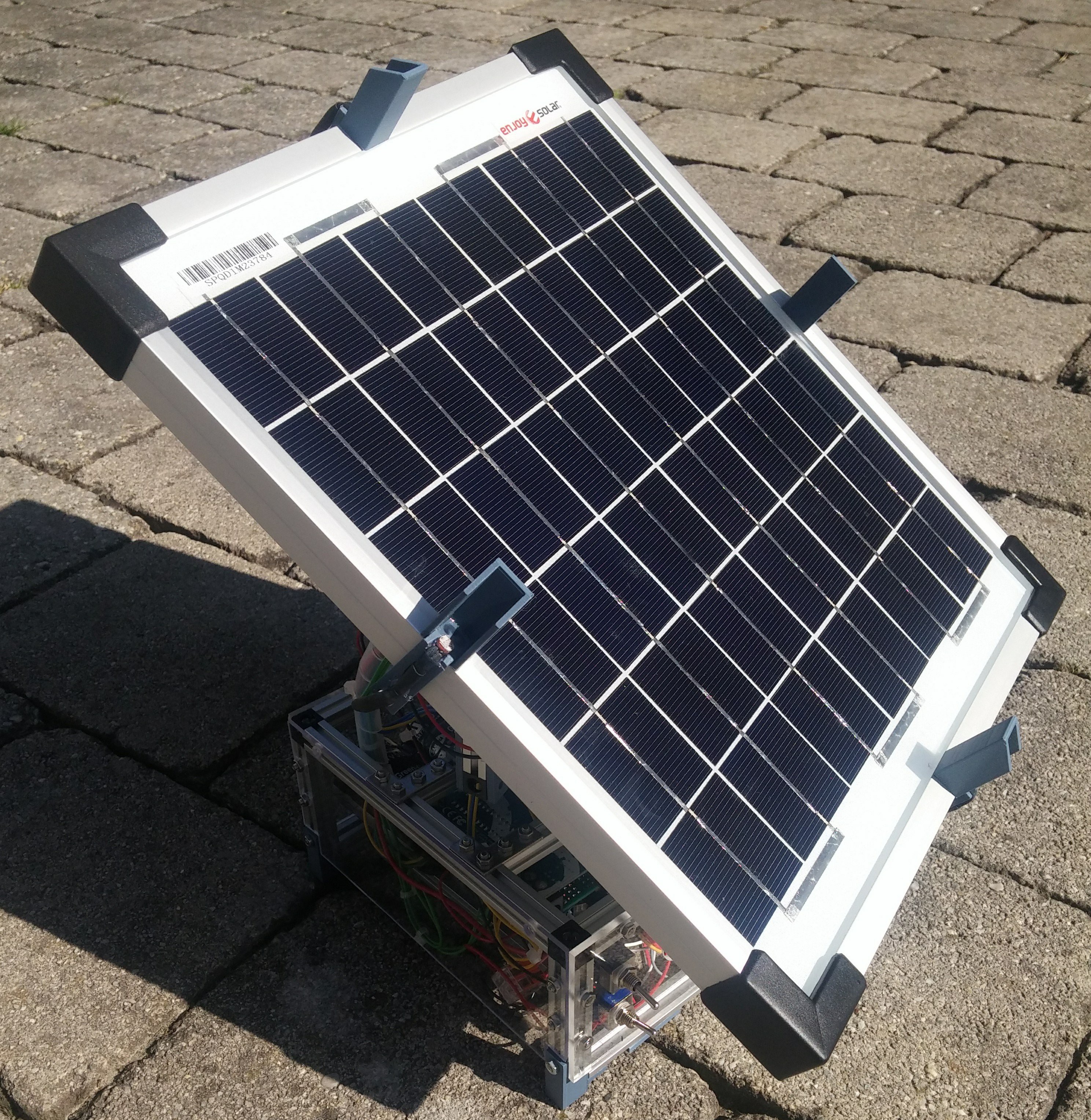
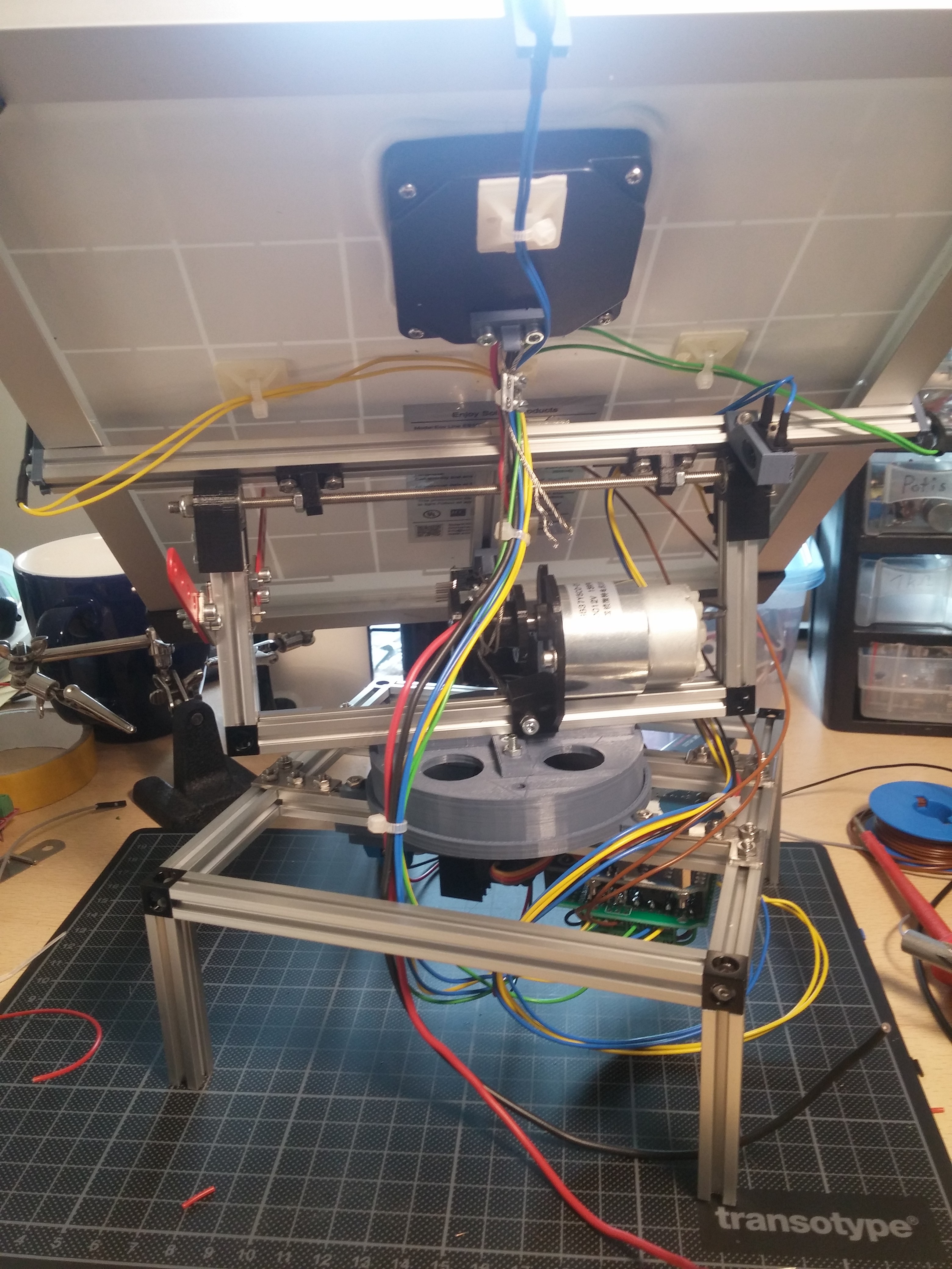
I started to build a basic construction and a frame for the 18V 10W sun-panel with MakerBeam-profiles and then tried to move the whole thing with servos. As you maybe imagine this doesn't work very well and so I began to play around with an slow 12V DC-motor, i had lying around on my desk. It tourned out that this was the best way to change the angle of the panel. I added some endpostion-switches and it worked quite well.
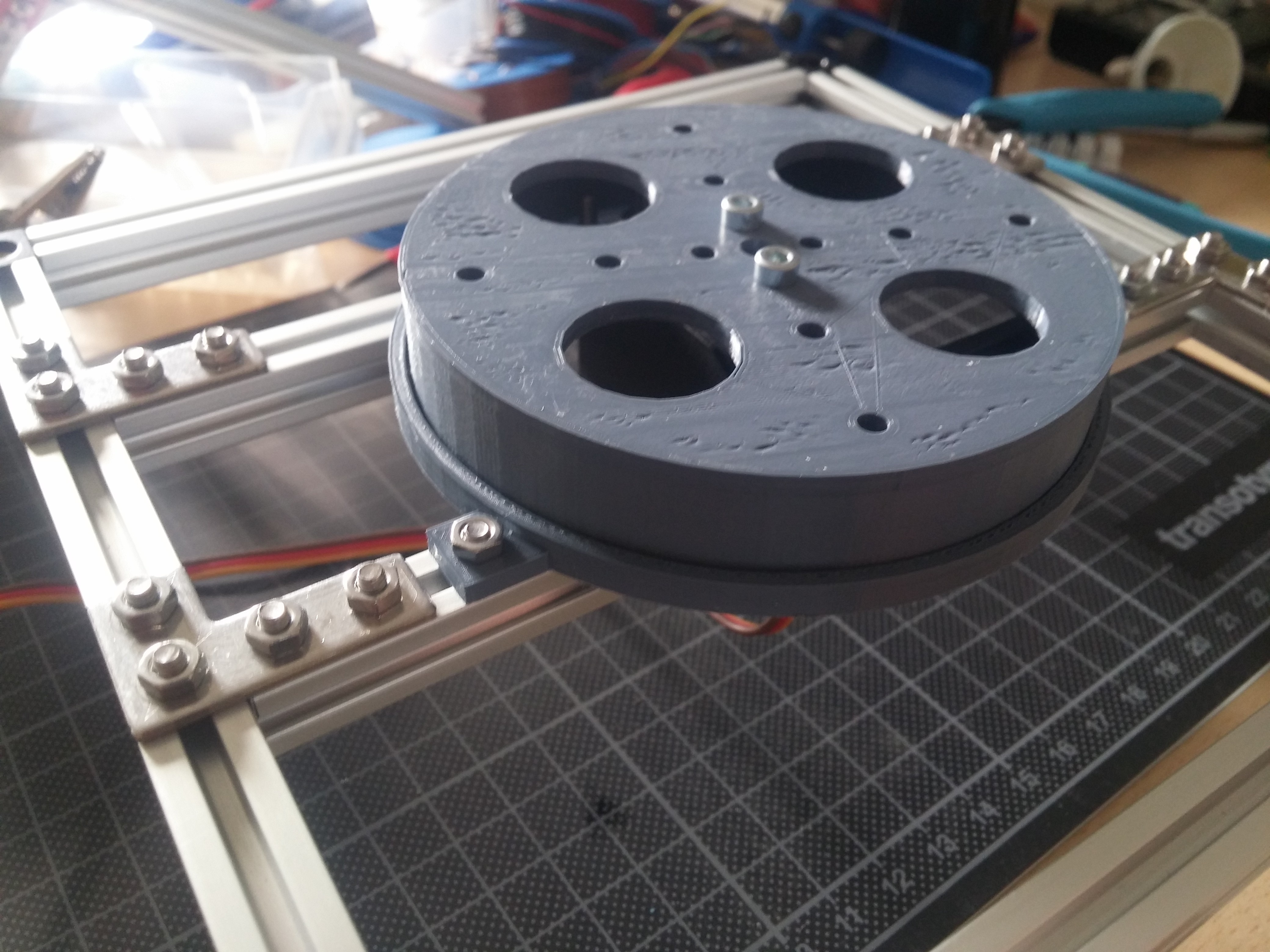
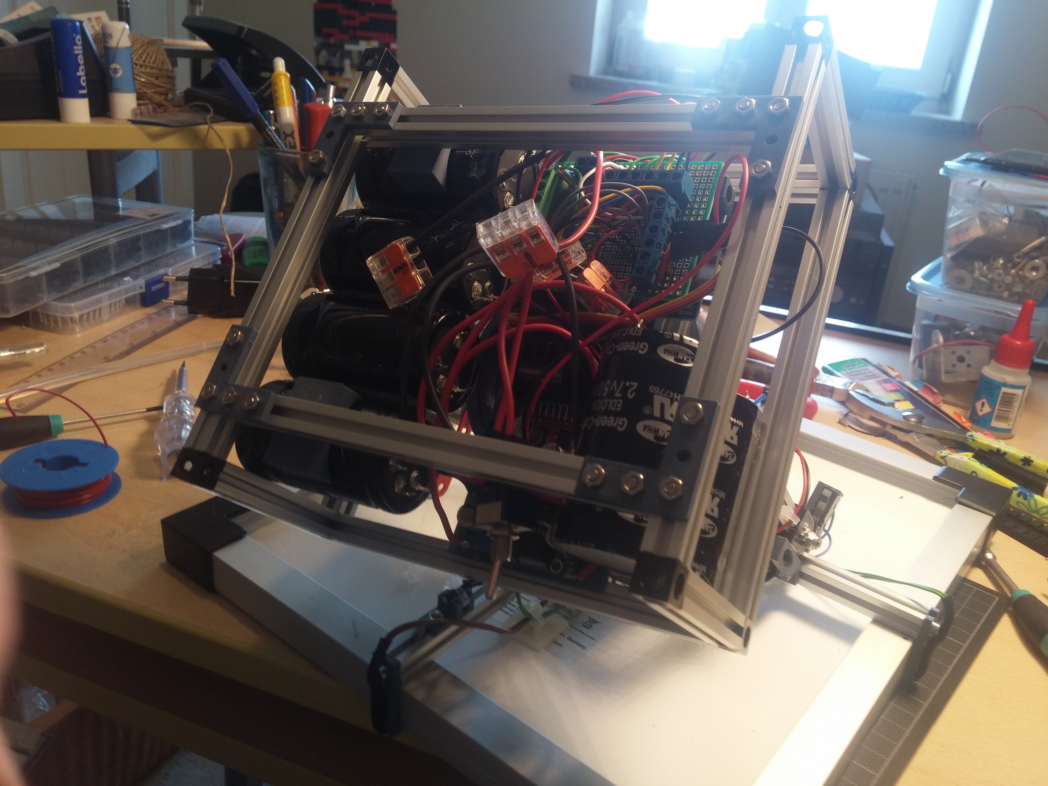
To rotate the hole construction, i printed a platform that can be screwed on a servo. On top of that I put the DC-motor with the panel. After i had finished most of the construction, i started to put the electronic components (like the Arduino or the LM2596) in the base of my machine and soldered a small prototyping-shield for the Arduino with a few screwterminals and resistors for the LDRs, which are attached on every side of the plate.
To limit the angle of the x-axis i added two endswitches to the frame of the panel and to keep the logic of the servo correct i had to mount an tilt switch.
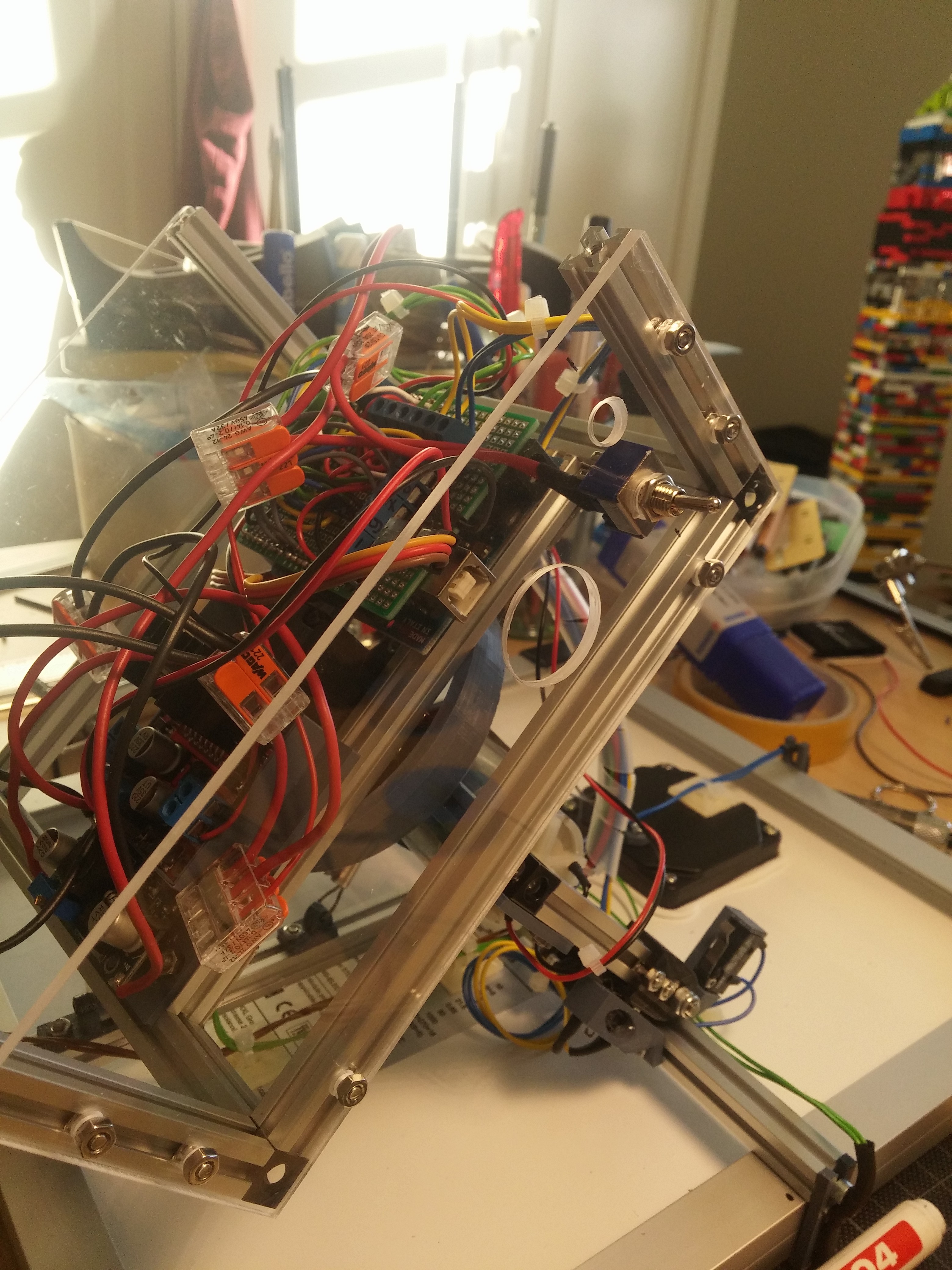
Now that all components are at the right position, i startend to wire everything up. This was quite a bit tricky because the wires shouldn't affect the moving of my machine in any way.
After a few tries and experiments also this chapter was completed and it was time to write the first lines of code to get the hole thing spotting the sun. (For now i thing the code i wrote is okey but maybe it could be more powersaving or whatever. ) With the written code and a working machine it was hard to wait until the weather was good enough to test it out and see if it works the wished way.
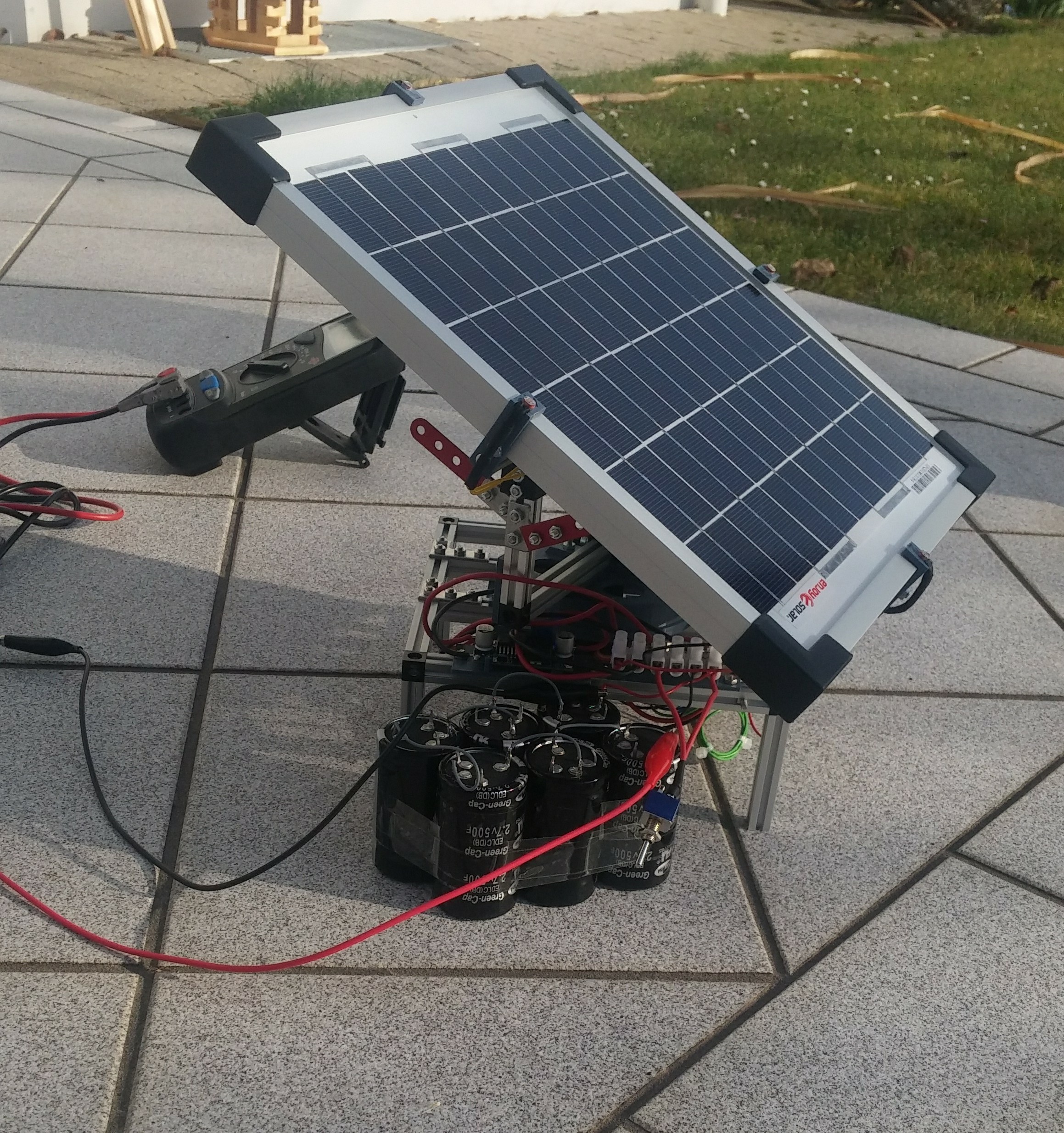
Finally the day arrived but the result wasn't that nice. The Problem was the energy needed to power the motors was to high for the sun panel and so everything was moving very very very slow. To solve this problem I quickly grapped a few super caps (500F 2,7V * 6) solderd them in series and added them in parallel to the 12V step-down-module. It needed a few minutes to charge them up by the solar panel but in the end it was quite a good result.
After solving this problem the next one appeared instantaeneous: The space in the base-construction, what was left, was not that much but the super-caps where quite big. This meant a lot of pushing around cables and parts, till the caps could be added but it was really worth it. I managed to build a construction witch holds all the caps and makes an easy removing and changing possible.
To give my device a nice look i cutted plexi-glas (2 mm and 4 mm) in the right shape and mounted it. Furthermore i drilled a few holes in the plexi-glas to fixate switches and to enable programming the arduino without having to remove the glas. With one of the switches you can shut down the power of the hole device, the other one stops the panel and holds the position. The second point is mostly interessting for uploading new code to the Arduino.

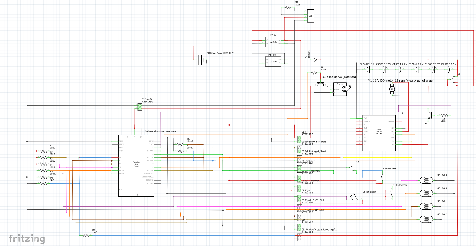
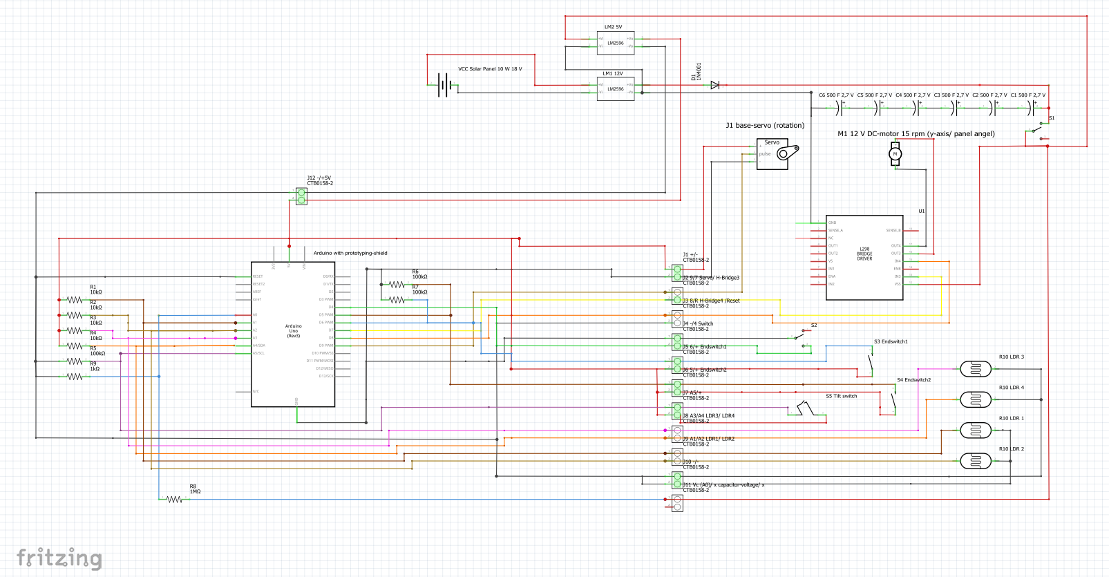
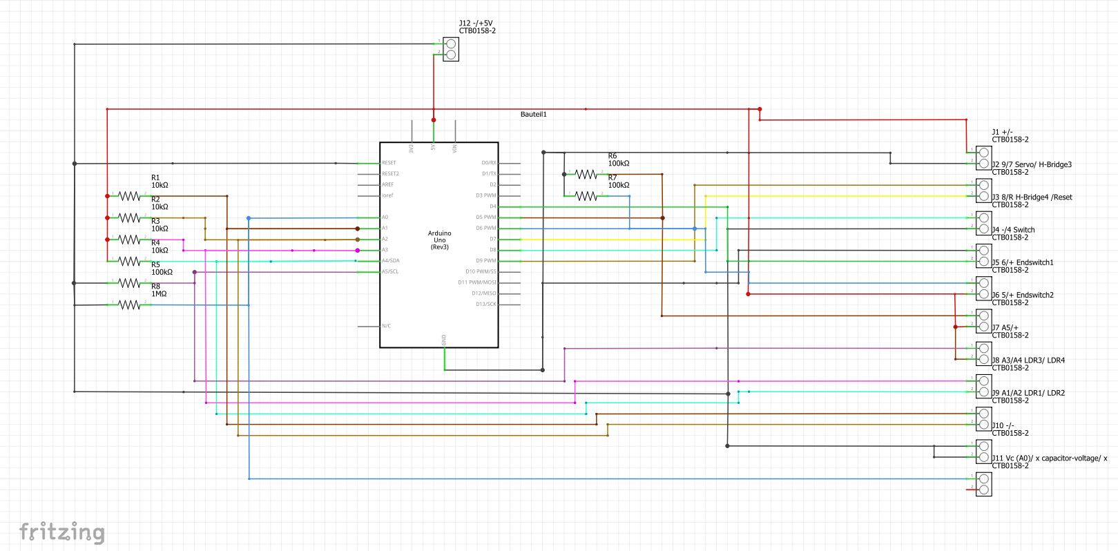
After some time working on this project, I realized that a plan would be a really handy thing. And so i spend some time, creating a plan with "fritzing". Here you can see the result of this.
As you can read in the beginning of the text, the purpose of my machine is to charge up and power things in the wild, to do this I use an USB-slot, that i removed from an old printer.
To cut down the energy consumption of the servo and the l298N-chip I integrated two transistors into my circut, which are shutting down the voltage if no action is happening. In future tests i will measure how much power we are saving exactly with this method.


 Daren Schwenke
 Hari Wiguna
 Richard Hogben
Nice idea, but with solar panels it's always the same:
If you need more power just add another solar cell. Cooling is extremely inefficient and peltier elements are really power-hungry.
Same with tracking: If you don't have space for a second/third panel that's okay, but the tracking mechanics are to be sealed really well, need maintenance, ...
Just be sure to add a MPPT-circuit https://de.wikipedia.org/wiki/Maximum_Power_Point_Tracking...