Close
0%
0%

Raspberry Pi Zero W desk clock

An LED desk clock driven by NTP on a Pi Zero W

Similar projects worth following
When I was in college, I bought and built a Heathkit GC-1000 WWV clock. Since then, I've been somewhat interested in accurate time measurement. I recently designed a GPS driven clock, but sometimes your local WiFi reception is better than GPS (say, indoors). For those circumstances, a clock that gets time from NTP over WiFi would be preferable. The newly released Raspberry Pi Zero W makes this quite a bit simpler to achieve

If you haven't seen my GPS clock, it's the starting point for this project.

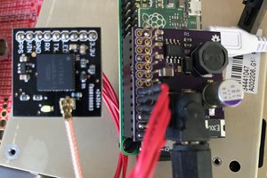
The Pi Zero W clock takes the GPS clock and lops off the microcontroller and GPS stuff. What's left is the MAX6951 LED display controller. This chip is driven by SPI, which, quite conveniently, the Pi Zero supports rather easily.

Since I also already have a pile of 5V power supplies that terminate in 2.1mm barrel connectors, it's a simple matter to keep the power jack on the board and just supply 5V to the Pi over the GPIO header.

The Pi will simply boot up and run a small daemon to drive the SPI display to show the current time. The Pi will use NTP over WiFi in the usual manner to get time.

The accuracy that's likely to be achieved will be easily an order of magnitude or so worse than the GPS clock, but keep in mind that the display granularity we're going to support will be only 100 ms. The GPS clock claims an accuracy on the order of a hundred microseconds. This clock will likely only be accurate to within a few milliseconds. That's still quite good enough for a clock display for humans. If you want to do better, you can set up a stratum 0 server on your local LAN and use that as a source. If you do that - even over WiFi - your system clock accuracy should be within a few hundreds of microseconds (if not under). Alternatively, you could connect a GPS receiver module's serial I/O and PPS up to the pi (see instructions for that in the Pi NTP server project), and likely get much better.

The daemon for the display will take some extra pains to set itself up for realtime priority and lock itself in memory, but a Pi Zero with nothing else to do likely won't have any trouble keeping up.

The one issue with this concept is that there's a chicken-and-egg problem with getting it on WiFi. You need to talk to the zero to configure it to use WiFi, and there's no way to talk to it wirelessly before you do. PiBakery offers an ideal way to work around this problem. You can use a PiBakery recipe to write a custom Raspbian image out to an SD card. On first boot, the PiBakery scripts will configure things as you request, including a WiFi network and password and optionally changing the default user password. The PiBakery recipe included in the project source tree will also enable SPI, the serial console, and will download the clock daemon source, compile and install it, and configure systems to launch it at boot. It will then reboot the Pi.

To facilitate serial console configuration, the clock board will break out the console lines to a 3 pin header (and provide a diode-pullup level shifter on the input line). You can connect it up to a TTL serial port (like an FTDI-be-gone) and USB to a host computer from there. Alternatively (if you're not using the Pi Zero's USB port for something else), you can configure the USB OTG support to provision a "gadget" serial port. In this case, you can connect an ordinary microUSB cable between the zero and a host and the host will see a USB serial adapter. Use terminal software to open that virtual serial port and you'll get a login prompt from your Pi Zero.

Once you have the Pi on the network (and your network has Internet connectivity), the default NTP configuration should be good enough to properly set the time. You can change the daemon's default command line arguments if you wish by editing the systemd config file and you can change the clock's timezone by changing the system timezone.

The circuit on the board is fairly simple. The 2.1mm jack receives 5 volts from an external supply. To protect against spikes there is a 5 volt TVS diode and a bulk capacitor. Next there's a ferrite bead to try and prevent power noise from being radiated from the supply cable. The 5 volt rail is then run directly to the 5 volt supply pins on the Pi GPIO header. You can power the system from either the 2.1mm jack or the Pi's power input USB connector.

The MAX6951 has the ability to supply constant current to the LED segments. What this means in practice, however,...

Read more »

pi_clock_1_0.pdf

Schematic

Adobe Portable Document Format - 41.65 kB - 03/04/2017 at 17:16

Preview
Download

pi_clock_1_0.brd

EAGLE board file

brd - 125.99 kB - 03/04/2017 at 17:15

Download

pi_clock_1_0.sch

EAGLE schematic

sch - 274.42 kB - 03/04/2017 at 17:15

Download

  • Compute module pi clock?

    Nick Sayer09/14/2017 at 02:50 0 comments

    In principle, the Raspberry Pi compute module is the thing you're supposed to use to embed into projects like the clock. I've done a little bit of looking at it, and in theory it is possible to design a board that would accept a compute module instead of a pi zero w. There are a couple of fairly big problems with the idea, however.

    • The compute modules are very expensive compared to a zero. The CM3 is actually the same price as a Pi 3B while being far less capable (at least without breaking out a whole lot of connectors and stuff).
    • The clock would need to supply 3 different voltages to the CM.
    • It would need to have a USB connector and would need some special circuitry to allow the special USB bootstrapping to initialize the on-board flash (you could initialize the CM separately and not include that support on the clock, but that makes it a whole lot less maintainable by the end-users if, say, they have to replace their CM). Adding a OTG capable USB port would be necessary in any event for either wireless or wired networking.
    • It remains to be seen if an equivalent 40 (or 26) pin GPIO header could be added to the clock to support traditional expansion. How that could be made to fit would be the next big question.

    The nice thing about such a beast is that (with the CM3) it would have the same CPU performance as a Pi 3, but the actual benefit of that for the purpose of the clock is questionable at best.

  • Dual clock display

    Nick Sayer07/18/2017 at 19:45 0 comments

    I haven't actually done this, but I've been considering how to make a dual display variant, perhaps as a display piece for an astronomical museum - one display could show LAST, the other standard time.

    To do this, you're going to probably have to come up with some new mounting / case scheme, obviously.

    But electrically it's fairly straightforward. Assemble the first clock as usual, with a pi zero w. This display will be display 0.

    Next, build an identical board, but leave the 40 pin GPIO header off. You'll be using 5 jumper wires to connect from this board to the GPIO header on the other board (actually, on the Pi that's connected to it). This will be display 1.

    The connections required:

    Board 0Board 1Function
    22+5
    66GND
    1919MOSI
    2323SCK
    2624CE1 -> CE0

    Thusly connected, the second board will take power from the first, and share the SPI bus. The two clocks will keep out of each other's way by using different nodes in /dev. You simply need to run two different clock daemons, with one of them using /dev/spidev0.0 (for the display connected directly to the pi), and the other using /dev/spidev0.1 (for the auxiliary display).

    You do need to make sure your +5 volt power supply is beefy enough. You should count on at least supplying 500 mA.

  • Bolt-on GPS

    Nick Sayer05/17/2017 at 05:22 0 comments

    I've got two Pi Zeros in the NTP pool, each as a GPS based stratum 1 server.

    One of them is a Pi Zero connected up to the diagnostic port of one of my GPSDOs. The other is one of these Pi Zero clocks, but with a GPS breakout board hooked up as well.

    Essentially, that one is a mash-up of this project and a the Pi GPS NTP project.

    Since the new laser cut wood and acrylic case has a cut-out for the GPIO headers, it's easy to tack the GPS receiver on. The one downside is that you lose the serial console pins.

    The next thing I'm going to do is to make a new board that's a modification of the breakout board that makes it purpose-built for the pi. It will have a 16 pin header to mate with the left-most pins on the GPIO header. It runs the GPS module from the 3.3v supply provided by the pi, and 5 volt power is applied through a blocking inductor to the antenna jack to power active antennas.

    EDIT:

    If you have one of my GPS Disciplined Oscillators, you can use this little board to connect to the diagnostic port. This allows you to make a mash-up of all three projects - the GPSDO, the clock display and the GPS NTP server.

  • Sidereal clock

    Nick Sayer05/12/2017 at 00:18 0 comments

    The Pi Zero W clock is ideal for displaying either Greenwich Mean Sidereal Time or Local Mean Sidereal Time - you just have to change the software around a bit.

    I've done just that now. In the GitHub repo there's an SPI_Sidereal.c along side the rest. If you run it without any arguments, it displays GMST, but you can specify your longitude (+ for east, - for west) with -l and you'll get LMST. AM/PM is not available - the clock only shows 24 hour mode (I can't imagine anyone wanting otherwise), but the -B, -c, -d, -b and -t options are the same as before.

    I actually recommend turning the tenth digit off on the sidereal clock. The clock displays sidereal time, but the updates are still synchronized against Unix time, and the two have differing second lengths, so it's not likely to be that accurate (never mind the fact that the time is calculated with floating point math).

    There are other options you can use as well - you could use the clock as a countdown timer display, or perhaps an elapsed timer display... It's all fairly straightforward changes to the existing code.

  • Mounting

    Nick Sayer03/28/2017 at 15:08 0 comments

    If you want to mount the clock in a chassis, here's the recommended method. Drill number 4 machine screw holes to line up with the four holes in the corner of the board. Thread 1 inch bolts through from the outside. On the top left bolt, thread a 3/16" spacer. On the other 4 bolts, thread a 5/8" spacer.

    Next, separately thread a machine screw through from the top of the Pi through the right hand hole (the one not in a corner). Between the display board and the pi insert a 3/8" spacer. Top the bolt (on the display side of the display board) with a nut.

    Add a 3/8" spacer between the pi and the display board and then thread everything over the 4 corner bolts. What you wind up with is a 5/8" spacer on the three corners that don't involve the Pi. On the corner where the Pi is, there's the case back, a 3/16" spacer, then the pi board, then a 3/8" spacer, then the display board then a nut. This works because the Pi board is about 1/16" thick. The remaining bolt doesn't go through the back chassis, it just holds the Pi to the display, with the two separated by a 3/8" spacer.

    The 3/16" space between the Pi and the back is just enough for the board and all of the connectors to clear the back, but it's recommended that this mounting method be used only for wood or plastic cases. If you use a metal case, then you probably should add at least another 1/8", making the bottom corner spacer 5/16" and the other corners 3/4". The inter-board spacing (with the recommended GPIO male/female header pair) remains 3/8".

    You metric people are on your own. :)

  • Another console access idea

    Nick Sayer03/24/2017 at 15:29 0 comments

    This hadn't occurred to me until I read more of the PiBakery source.

    Another option for getting convenient console access is to configure the USB OTG port in target mode as a USB serial interface. In PiBakery, this is the "OTG serial" block.

    This only works if you're not using the USB port for anything else, which means you're using a Pi W's WiFi to get network access. If you're using the OTG port for Ethernet or WiFi, then this isn't an option.

    In principle, what this means is that once this is set up, you could just plug an ordinary micro-USB cable between the OTG port and a host and the host would see a USB serial interface show up. Open that port with terminal emulation software and you'll get a login prompt.

    EDIT: I tested this out and, sure enough, it works great!

  • RA OTG adapter FTW

    Nick Sayer03/21/2017 at 15:13 0 comments

    If you plan on using Ethernet for the clock connectivity, one issue is that the way the Pi is oriented on the back of the clock board, it's awkward to plug in a normal OTG adapter cable, since it exits down towards the bottom of the clock.

    The solution is one of these I found on Amazon:

    It's a right-angle OTG adapter cable. This one is particularly nice because it turns to the left, which means that it doesn't block the power port, if you need/want to use it (of course, you'd want a micro-usb cable that was right angle the opposite way for that one).

  • PiBakery as an easier way to bootstrap?

    Nick Sayer03/21/2017 at 15:03 1 comment

    One of the problems inherent with this project is how to go from a blank SD card to getting a Pi Zero on WiFi and running the clock code.

    A quick google for customizing Raspbian images led me to PiBakery. This looks like the easiest way to get the job done.

    To that end, I'm going to see if I can develop a PiBakery block to fetch, compile and start the clock daemon. If I can do that, then there's also a prospect for sharing a canned PiBakery configuration that will create an SD card to just do everything required and write an SD card in one step.

  • On accuracy

    Nick Sayer03/20/2017 at 22:22 0 comments

    I've been pretty dramatically under-promising on the accuracy of the clock, talking about the tens of milliseconds or so.

    It turns out that my experimental observations suggest the clock does much better than I expected.

    My means of testing is to take 240 fps slow motion video with my phone of a GPS clock and a Pi clock.

    The GPS clock is architecturally similar - it's the same MAX6951 display driver chip, but it's being run by bit-banged SPI from an ATTiny841 that's listening to a GPS receiver module. The GPS clock is driven primarily by the PPS. What inaccuracy there is is due to the interrupt processing latency, plus the time it takes to update the display with SPI. My guess is that it's maybe a maximum of 100 µs slow.

    When I take video of the two together, the two tenth-of-a-second digits change almost always in the same frame. For 240 FPS video, a frame is 4.16 ms, so when they switch in the same frame, they're at least that close to each other. Giving it the benefit of the doubt, if it's within 10 ms, then that's still an order of magnitude better than the granularity (100 ms), so it's definitely a win.

    Oh, and this is comparing a Pi clock that's just running NTP over WiFi against 4 random hosts in the NTP pool. There's no local server involved.

  • One small bug

    Nick Sayer03/19/2017 at 02:24 0 comments

    I turned one of the boards I got back from OSHPark into a display for one of my stratum 1 NTP servers, so it could do double duty as an actual clock. One little gotcha with the GPS receivers I use is that sometimes they're two seconds fast for about 10 minutes. I attribute this to something to do with leap seconds - some bit of data relevant to leap seconds is only transmitted every ten minutes or so, and until the receiver gets it...

    So what happened was that the clock showed time two seconds fast for a while, then the display froze for two seconds and then picked up again.

    I'm pretty sure what happened was that the alarm system is set up to wake up at just the right moment to update the display. But if in the meantime the time has moved backwards, now you've got an alarm set for way in the future.

    I'm going to just let that one go. In general, the clock shouldn't need to be horsed around like that too much. And if you do, and the display gets stuck, you can just restart the daemon.

View all 15 project logs

  • 1
    Step 1

    Build the board

    The board doesn't have any particular special instructions for building it. All of the display modules and LEDs mount on the opposite side of the board from the surface mount components. When mounting the LEDs (AM/PM and the colons), all of the anodes should be in the bottom holes and the cathodes in the top. The colon LEDs should be mounted slightly up from the board so that their tops are more or less flush with the tops of the display modules.

    Mount a low profile 2x20 .1" DIP socket set on the component side (opposite side from the display) for the Pi GPIO header.

  • 2
    Step 2

    Physical setup for the Pi

    Mount a 2x20 .1" DIP header on the BOTTOM of your Pi Zero. For great justice, consider using a "double male" stacking header like this one (the benefit to that is you'll be able to connect other things on the top side of your Pi). You will plug that header into the sockets on the clock board. The component side of the Pi will face upwards.

    Before mounting the Pi on the clock board, thread a 3/4" 4-40 machine screw through the two holes adjacent to the header from the display side. On the component side, add a 3/8" spacer, then add the Pi on top. Firmly mate the header pins into the sockets. Add a lock washer and nut to the screws and tighten firmly, but not too tight.

  • 3
    Step 3

    Power test

    Apply power to the 2.1mm jack on the clock board. You should see some signs of activity from the green LED on the Pi. You won't see the LED display do anything at all - by default the controller chip boots up in sleep mode.

View all 15 instructions

Enjoy this project?

Share

Discussions

Similar Projects

Does this project spark your interest?

Become a member to follow this project and never miss any updates