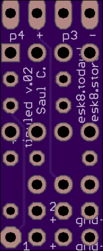
Close
0%
0%

Animated Led Brake/Turn signals for RC and Esk8

A custom programmable tail light for my custom electric skateboard.

Similar projects worth following
This is a tail light with integrated brake, turn signal, and timed animations never saw knightrider but I think it would be electric ;)

This project is based on the attiny85, ws2812 rgb leds and Arduino Ide.
I've created this as project page as a teaching/learning resource, for basic arduino programming, soldering, prototyping and 3d modeling with openscad. With this is mind the code is modular and overly documented (yes, that's possible!) to help teach beginners and allow easy modification and customization.

Designed for an electric skateboard but works with any RC tx/rx system with at least 2 channels.

The tiny reads input from a 2ch rc tx/rx system using pluseIn() on 2 digital pins, which means it works with any rc esc style project including rc cars/trucks/robots/etc anything with pwm and custom electric skateboards.

Ch1 - Steering wheel is used for turn signal control

Ch2 - Throttle is split and sampled for brake lights while still allow an esc to read the same signal.

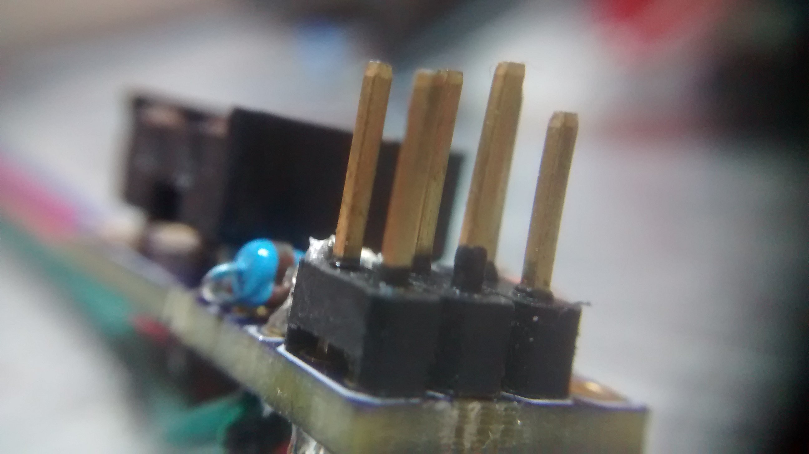
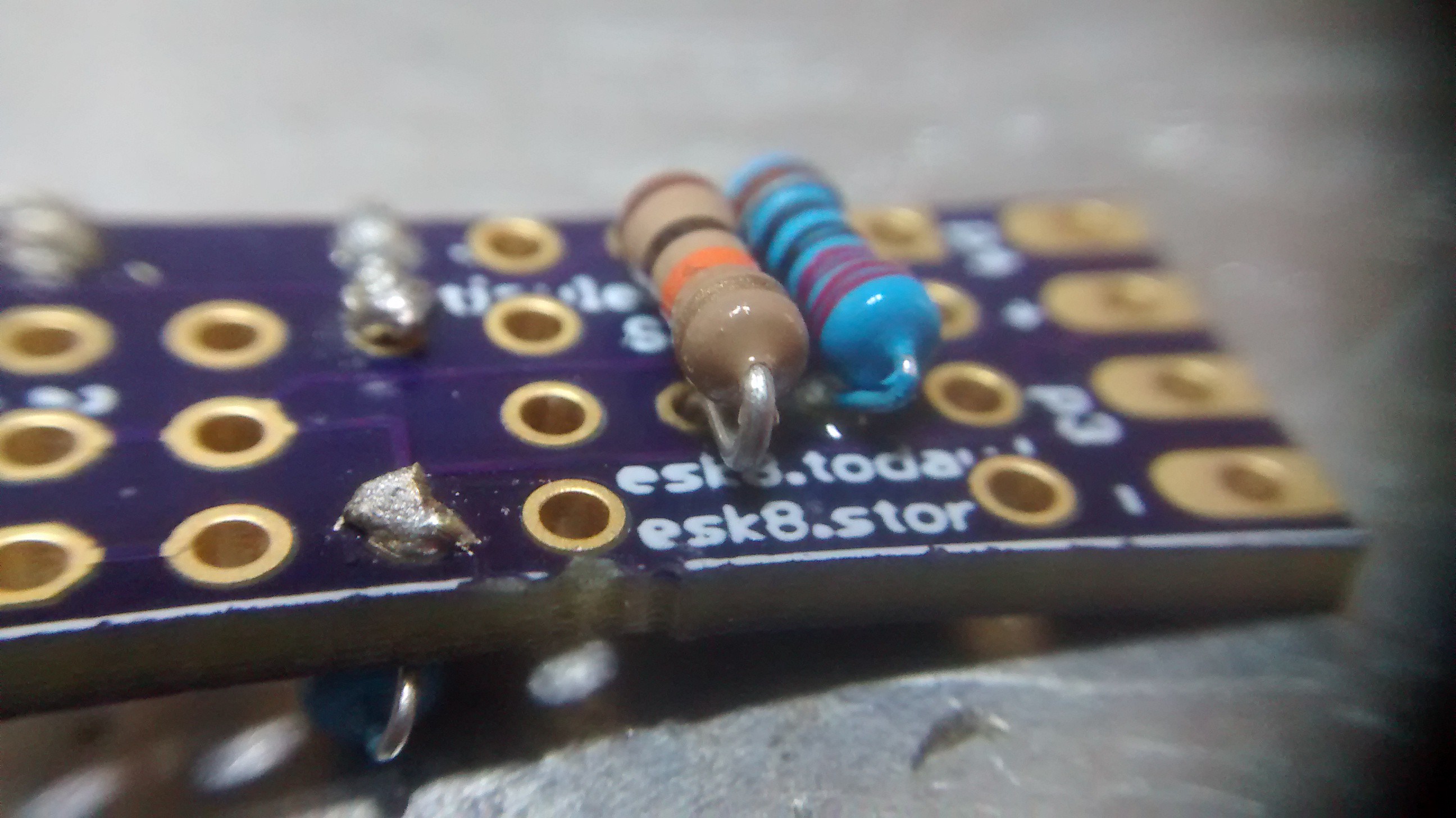
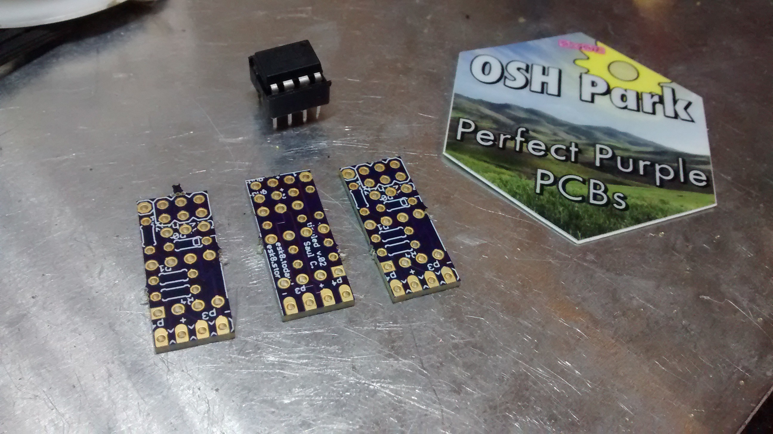
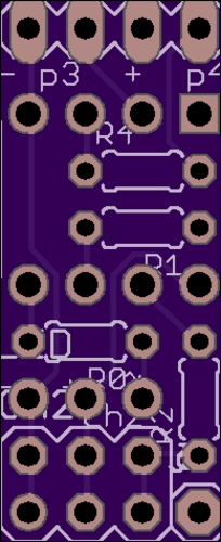
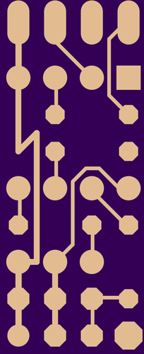
The hardware is designed to be as compact as possible, soldering through hole components with this schematic is quick, easy and elegant. So instead of creating a custom pcb, using perf board makes this a simple soldering project that doubles as a prototyping experience. It also means the design can be quickly adapted, customized and hacked with no cost and minimal time!

Turn signals are not required on an esk8 but this feature was inspired by the led display is (see video2 @ 1:30) the control feature can also be adapted to control a led headlight or aux/under glow lighting (testing but really another project).

The micro switch is not current used in the code:

Option 1: use it for configuration with the rx, for now configuration can be done by changing variable/constant values then reprogramming. (only 1 time for setup)

Plan B: change modes, brightness, colors, on/off (sleep mode).

or just ditch it in favor of a even more micro size.


Standard Tesselated Geometry - 623.51 kB - 03/16/2017 at 12:20

Download

  • 1 × attiny85 or similar microcontroller Microprocessors, Microcontrollers, DSPs / ARM, RISC-Based Microcontrollers
  • 1 × 8 pin dip tray
  • 1 × resistor ~200ohm
  • 2 × resistor ~1kohm
  • 1 × pcb Electronic Components / Misc. Electronic Components

View all 10 components

  • New custom PCB.

    Saul05/12/2017 at 04:36 0 comments

    finally understanding how to use eagle, got my first custom pcb in the mail today!

    Tested and working great, just need to make a few small adjustments to make soldering easier. ;)

  • Made a pcb.

    Saul05/03/2017 at 18:32 0 comments

    Turns out they are cheap when you can get them small enough. only 60 cent each from oshpark, they are going to save time and even smaller than before at 0.39x0.95 inch (9.86x24.13 mm) 2 layer board.

    No more switch, but pins 3, 4, gnd, vcc are broken out with fat pads and I had some fun with the routing. ^_-

    will post links/files when I get them built and tested.

  • Published Code

    Saul03/17/2017 at 13:27 0 comments

    The code is now available on my github under the apache 2.0 open source license.

    This includes both the Arduino code for input and animations, as well as the openscad and .stl 3d model for an 8x led module.

View all 3 project logs

  • 1
    Step 1

    Gather components and tools.

    Tools required:

    • Soldering iron with fine tip. at least 30Watts.
    • Box cutter/razer blade
    • helping hands clamps
    • wire snips
    • wire stripper or skill
  • 2
    Step 2

    Test and customize on a breadboard to make sure everything works properly.

    Tip. Use an extra Dip socket stacked up while programming, connecting/disconnecting is easy and wont damage the pins of the tiny. When the programming is finalized and tested remove the extra socket for solid connect that won't vibrate loose.

    You can still remove the tiny dip later if needed, just be careful not to bend the pins too much or they'll break off. -$1.1 :(

  • 3
    Step 3

    Test fit components to measure pcb size.

    Be patience and take your time place all the parts in a small footprint. about 30mm x 12mm is what I ended up with, very small.

    take note of the order, this can make some parts much easier to solder.

View all 9 instructions

Enjoy this project?

Share

Discussions

Similar Projects

Does this project spark your interest?

Become a member to follow this project and never miss any updates