Close
0%
0%

MakerNet

The fast, intuitive and modular way to make awesome portable projects that maximize creativity and sharing

Similar projects worth following
Challenge: Cool interactive electronic projects are hard to build, require a lot of esoteric knowledge and aren't modular and abstracted like software. The effort to scale up your idea to a something _shareable_ is even harder - so many cool ideas never make it past breadboards.

Solution: Modular, interoperable components on a common field-bus that can be wired in any order and work with clean software interfaces. Now cool projects are more like Legos!

Aspiration: Young makers will be able to share their projects with each other, creating a virtuous cycle of inspiration. The barrier to create cool things will become lower.

License: Open-source hardware + software.

Status: Concept in testing

Makernet simplifies electronics projects and makes low-level hardware act more modular and abstracted like software. I want to enable makers -- especially young makers -- to build cool projects with minimal effort.

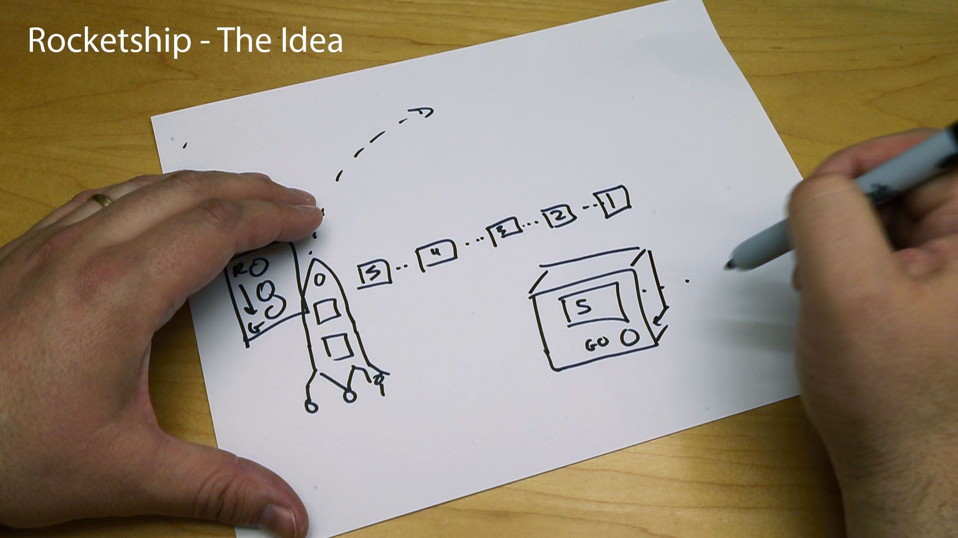
See the concept video below:

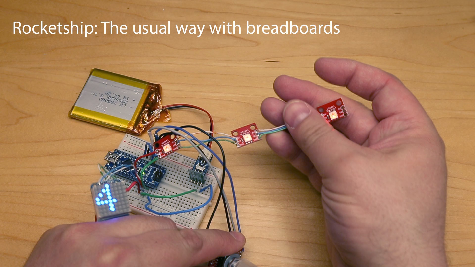
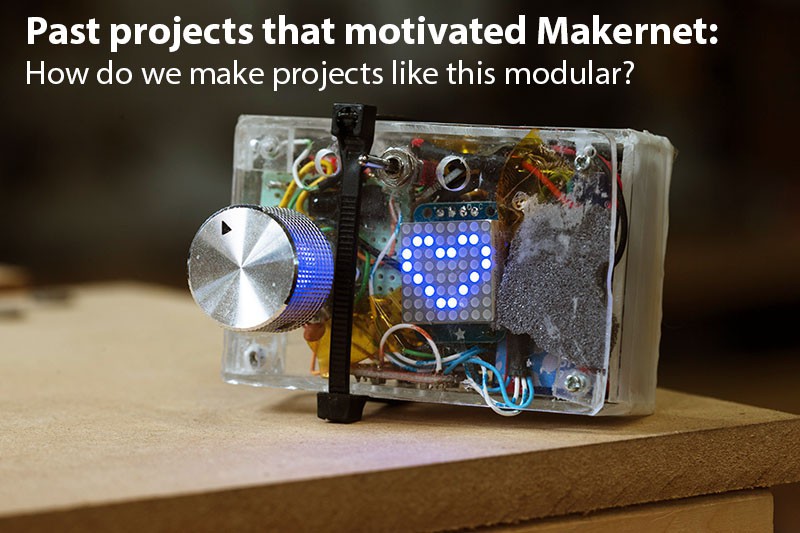
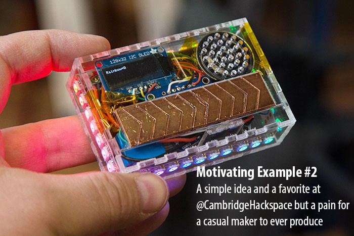
Everyone loves the thrill of building cool one-of-a-kind hardware. But lets be honest: hardware is pretty esoteric, much more so than software. Imagine someone raised on Minecraft and smartphones. How do we get new makers excited about building things? And how can experienced makers make projects more repeatable and less one-off and hard-coded?

Makernet addresses this challenge by creating a common robust bus network for all of the peripherals of a project. Everything is wrapped in a clean OO like paradigm. All you have to do is literally plug and play and forget about addresses, level shifting, battery charging, etc. Now electronics can be more like legos!

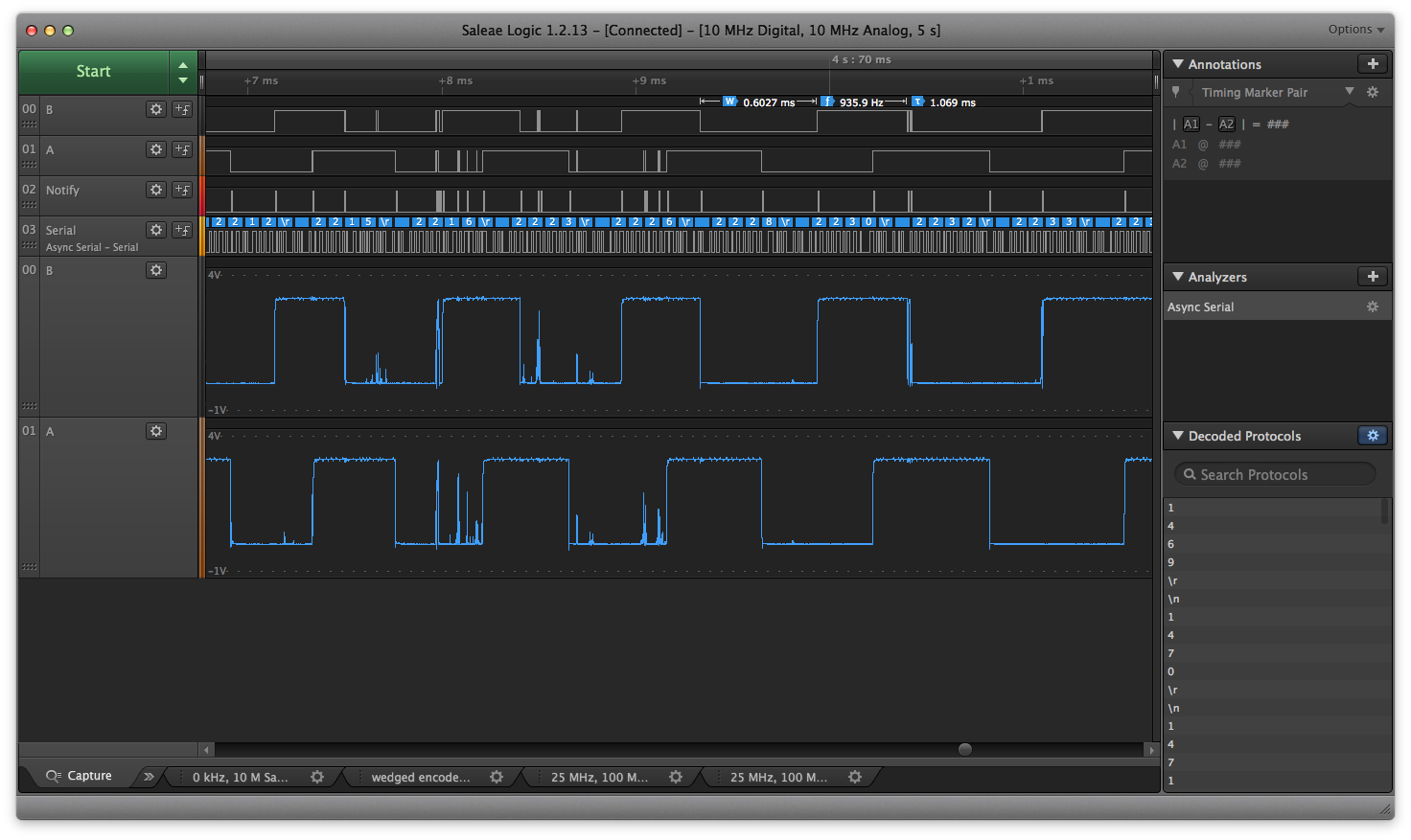
All of this is empowered by some clever hacking of the I2C bus and the availability of $1.00 SAMD11 ARM processors. A common event-based architecture sits on the inside passing messages back and forth.

Makernet is at the light concept stage. I have prototypes and I'm submitting this to the concept contest. I'd like to see if this idea resonates with other people.

Some of the intended features:

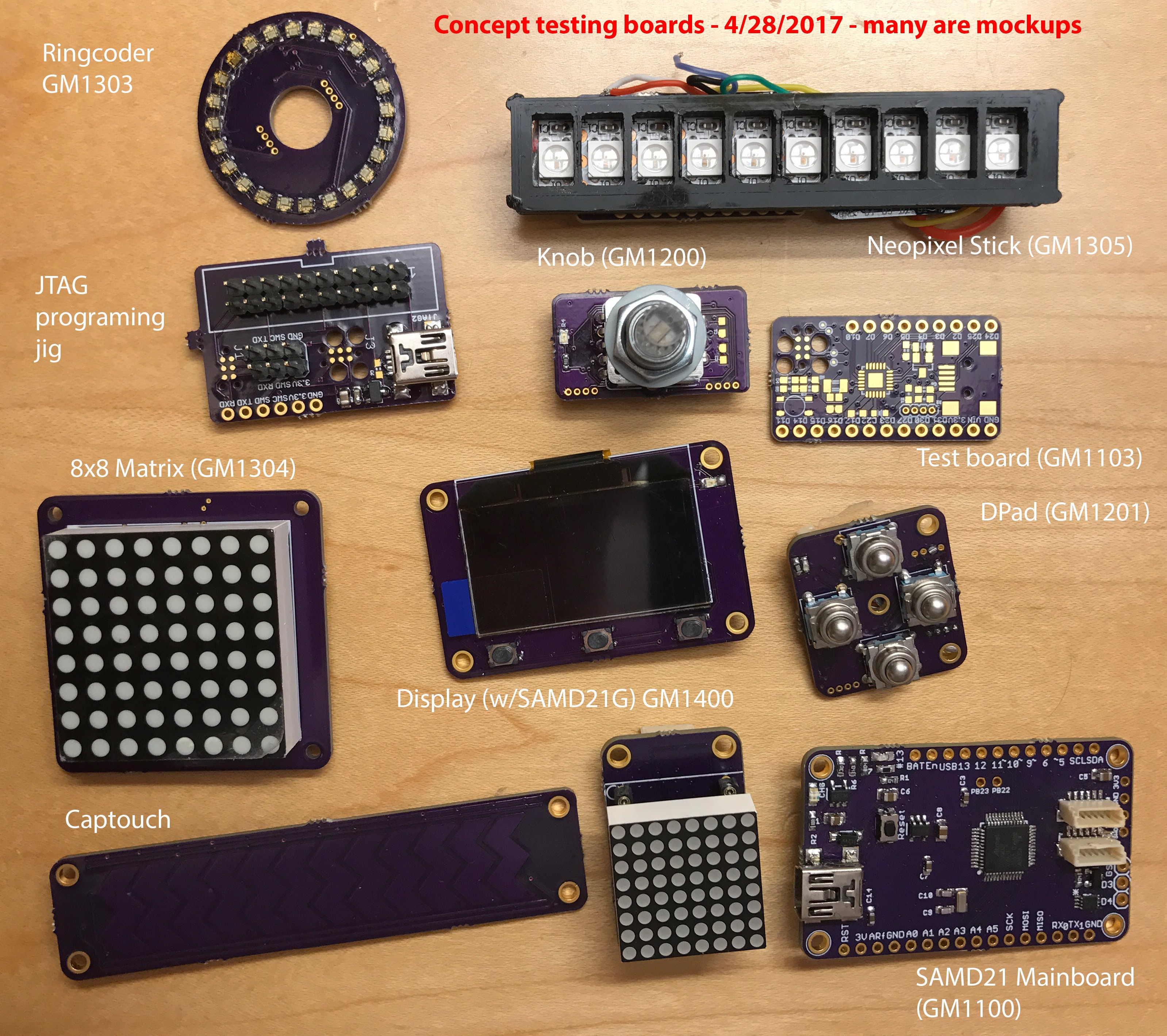
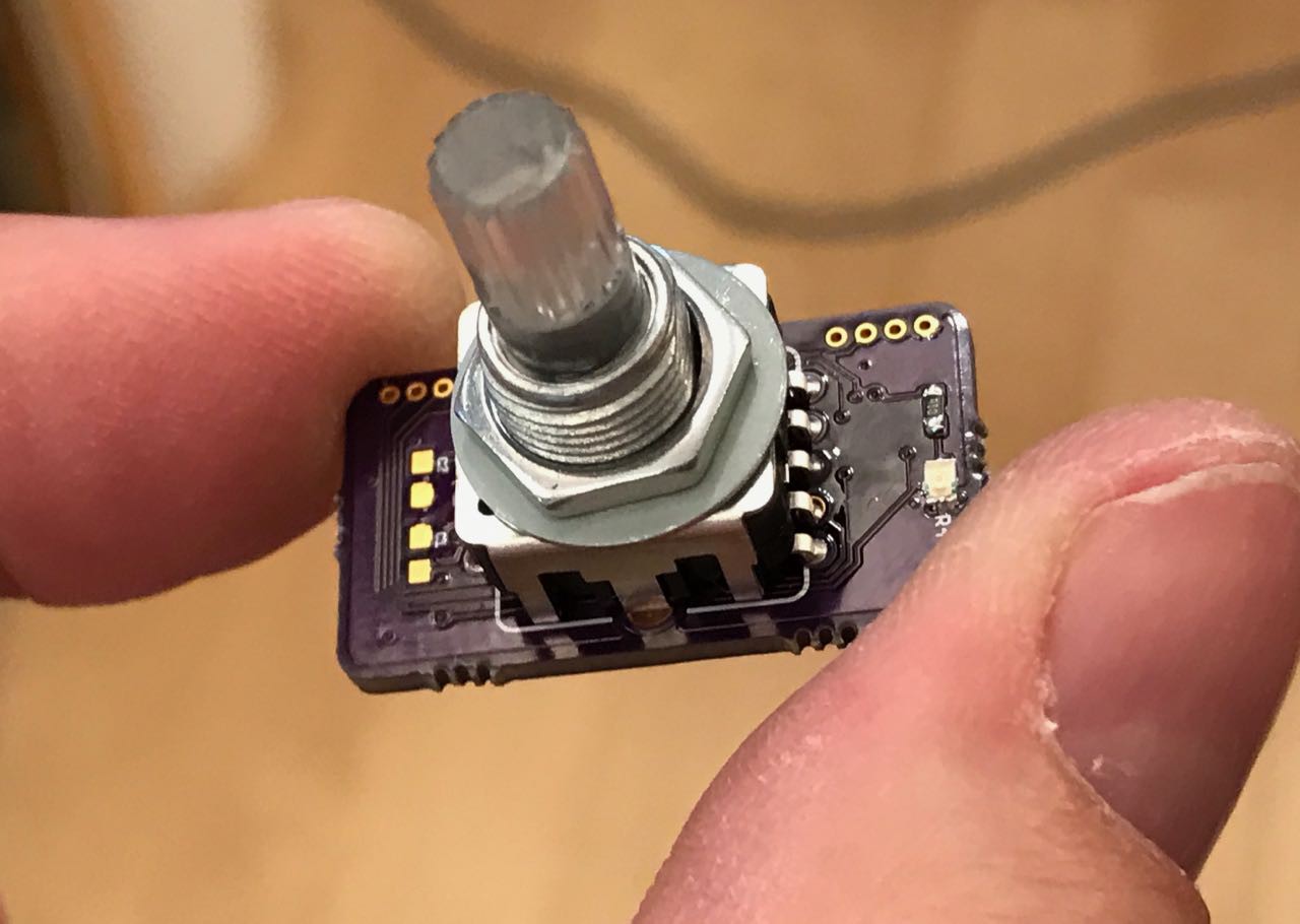
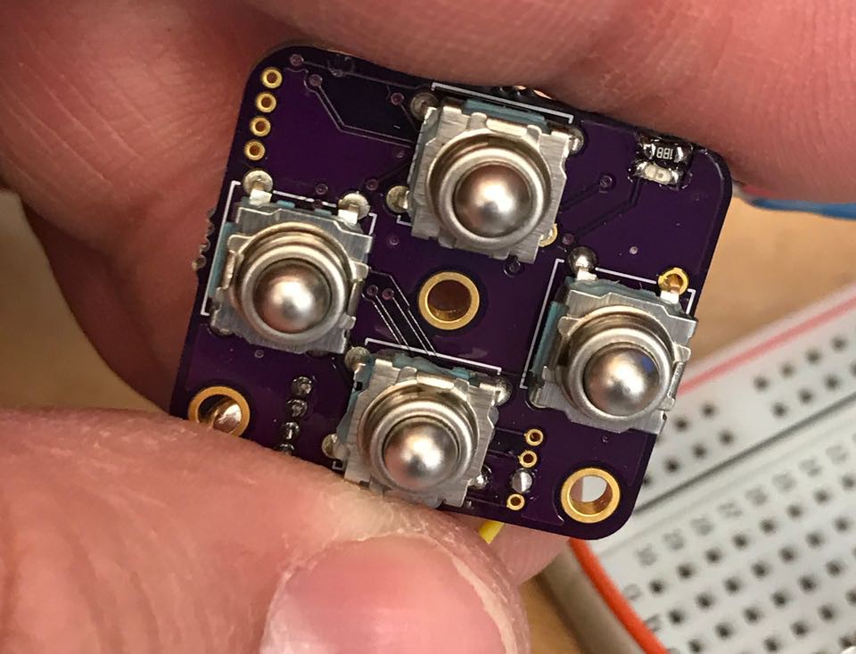
Pre-made modules: A small library of cool modules such as a rotary encoder, 8x8 matrix, capacitive slider, MCU board, neopixel driver, LCD/OLED screen, 4-way control pad, sensors, etc. All of them will be compatible and interoperable

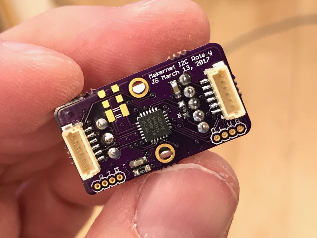
Bus Architecture: MakerNet will be built on a bus architecture (initially I2C, later RS485) that allows true "plug and play" for most projects

No Soldering: Everything is connected with JST-SH 6 pins and can be daisy chained

Case plans: Every component has a clear mounting strategy, eliminating guesswork on how to put it into a case. Mix and match modules to create the control panels of your dreams! Everything flush mounts with countersunk M2 hex flat-head screws.

Low Power: All modules can be shut down into a low-power state consuming only a few microamps, meaning your projects won't need on/off switches

Battery management: The base MCU board will support LiPo charging and charge monitoring

USB programable with Arduino: The core MCU will be either the SAMD21 or possibly the Teensy 3.2. The core module will expose a USB port to the outside of your case.

Common libraries: Programming is largely event-driven

Makernet i2c GM1100 SAMD21-M0 v05.sch

SAMD21 Mainboard early prototype (may have glitches)

sch - 283.41 kB - 06/02/2017 at 20:34

Download

Makernet i2c GM1100 SAMD21-M0 v05.brd

SAMD21 Mainboard early prototype (may have glitches)

brd - 154.62 kB - 06/02/2017 at 20:34

Download

MakerNet i2c GM1200 rotary thin v02.sch

Rotary encoder schematics (still early version)

sch - 234.43 kB - 04/28/2017 at 20:51

Download

Makernet i2c GM1400 SSD1306 v01d.sch

Schematic for a Makernet device that sports a 1" OLED screen. (Still early version)

sch - 246.59 kB - 04/28/2017 at 20:45

Download

Makernet i2c GM1400 SSD1306 v01d.brd

Board design for a Makernet device that sports a 1" OLED screen. (Still early version)

brd - 135.72 kB - 04/28/2017 at 20:45

Download

View all 6 files

  • 1 × ATSAMD11D Processor for peripherals, digikey 556-ATSAMD11D14A-MUT
  • 1 × ATSAMD21G18 Processor for mainboards (digikey ATSAMD21G18A-AUTCT-ND)
  • 2 × 455-1792-1-ND Top mount JST-SH 6 pin header
  • 1 × BSS138CT-ND N-Channel 50V 220mA (Ta) 360mW (Ta) Surface Mount SOT-23-3
  • 1 × 0603 Blue LED

View all 8 components

  • A full re-write of the framework

    Jeremy Gilbert07/21/2017 at 17:32 0 comments

    In the last month since my previous post, I've been busy reworking the entire Makernet software framework. Nearly every line of code has been rewritten and posted now to github here: https://github.com/jgilbert20/Makernet. The major advantages of the rewrite is pluggable support now for datalink layers other than I2C.

    The initial version of the Makernet code was long overdue for an overhaul. I had originally cobbled it together when I was still learning about I2C internals, and many of the concepts were based on EKT's code from the Modulo project. This was good for proof of concept, but I rapidly realized that the architecture would be impossible to maintain unless I created a proper networking stack.

    The new version of Makernet now is a fully OSI-relatable network stack with several layers. The first layer is the datalink, which provides medium access control, and forms input and output into frames. In the case of I2C, these frames are I2C transactions, but the code is generalized now to support nearly any way that a packet of information can get from A to B. 

    One nice advantage: my datalink layer handles all hardware concerns, making the upper layers of the stack fully hardware neutral. In fact, I implemented a second Datalink layer based on UNIX domain sockets which allows Makernet to run over MacOSX and Linux interprocess signalling!

    Once frames leave the Datalink layer, they move up to the Network layer where they are interpreted as packets and dispatched to various registered handlers called Services. Because the packet format is constant across different datalinks, every part of the software code can interchange with new transport protocols like RFM69HW radios or RS485.

    The code is now about 20% more compact than it was before, and all of the packet routing is now 100% object oriented, making it very clear to understand how packets and information flow between layers and also assisting in expanding the framework in the future.

    The next innovation was the removal of command syntax entirely from the makernet specification. In the early version, there was the idea of a command that got sent from a master device to a slave device that caused something to happen. This imperative syntax is very easy to implement but causes a number of problems. First, it does not handle irregular communications very well. Say your command from A to B is lost in the network. Do you just sit there polling for an ACK, while the rest of your code grinds to a halt? 

    Furthermore, commands make it entirely too easy to forget about state, which can be very pernicious in a truly asynchronous programing model. Consider the example of a neopixel strip N and a controller/master C. The code on C fires off a bunch of commands to draw some pixels. What happens if strip N disconnects and reconnects? Or experiences a software reset? Suddenly, the code no longer functions as you intend, because each "command" to the strip was actually updating state on the remote node and now all that state is lost. 

    To remove the imperative command syntax, I created a built-in mechanism called mailboxes. In this model, both a master and slave device share a set of connected, automatically synchronized small buffers. When one buffer is updated, the buffer on the remote end is synchronized automatically by the networking services. Now, all of the state assumptions are clearly defined. The mailboxes are defined as clean C++ object types that can be subclassed and adapted to nearly any type of communication need including streams. 

    You might think a heavy OO framework would be too much for a small embedded framework. I certainly was worried about this, especially virtual functions which implement a hidden jump table on each object type. However, my extensive testing has shown that in fact this new architecture is faster for most operations. The gain comes from the fact that the new framework never generates packets it doesn't intend to send because...

    Read more »

  • Polyphonic sound using I2C!

    Jeremy Gilbert06/20/2017 at 17:11 0 comments

    I'm a big fan of devices that make sounds as a way of interacting with the user. Pretty much every app, game and operating system uses sound in some way and it feels very natural.

    Sadly, adding high quality sound into a hobby-grade EE project is kind of a pain in the bottom. The Arduin supports a Tone library, but this is quite limited. You only get one sound playing at a time, and its basically a square wave. Adafruit and others have come up with WAV shields that fill in the gaps. With these neat devices, you can actually take sound files from your PC and set them up to be triggered by your project. The best winner in this category has to be the prop shield and audio library from PJRC.

    Even with these new devices, there is still a lot of complexity. And you don't really get everything you'd want.

    For instance:

    • Polyphonic sound- Most of these devices will play exactly one sound at a time. This doesn't correspond to how we normally expect interactive noises to work where multiple can be playing at the same time
    • Open source: Sadly most of the Adafruit and Sparkfun devices appear to be closed source firmware
    • Esoteric chips: I always feel cautious about integrating strange chips into my design. There is no reason why a $1 ARM chip can't stream I2S signals, so why have a dedicated player unless you actually need MP3?
    • Programing interface: Ideally you want to just send a single quick command and have the rest taken care of. I'd rather not consume a UART and work out how to send my device signals at 9600 baud.

    Based on these experiences, I was determined to integrate a true polyphonic sound player into the Makernet arsenal. Behold, the result of my efforts:

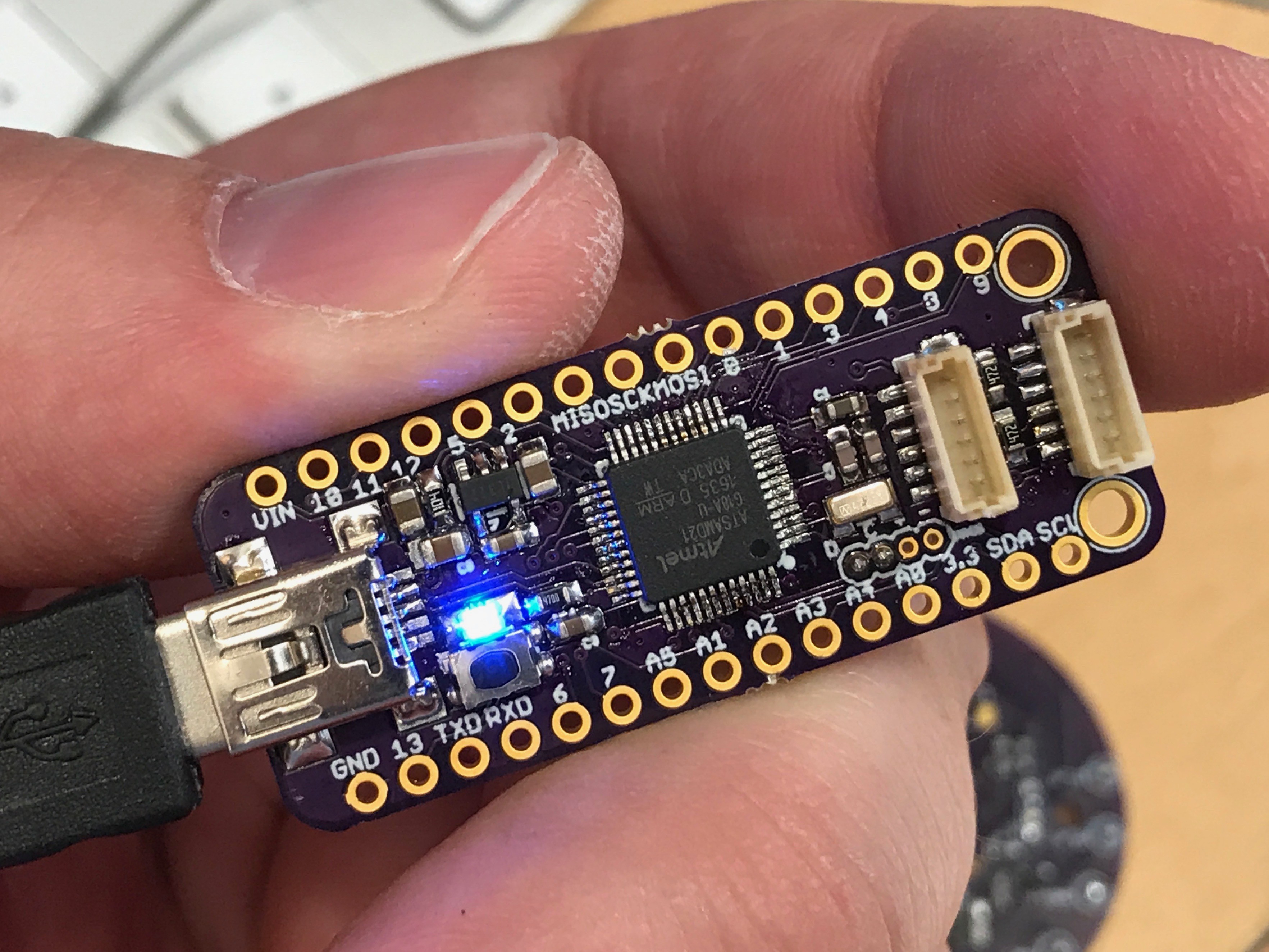
    As you can see, this little baby is still being prototyped (note the dangling USB cable and programing jig). It has a MicroSD card reader, a SAMD21G18 MCU and plays sound out of a MAX98357A I2S audio chip. Of course it also has the regular 6 pin makernet header that provides it with network, 3.3V and VIN (usually 5V).
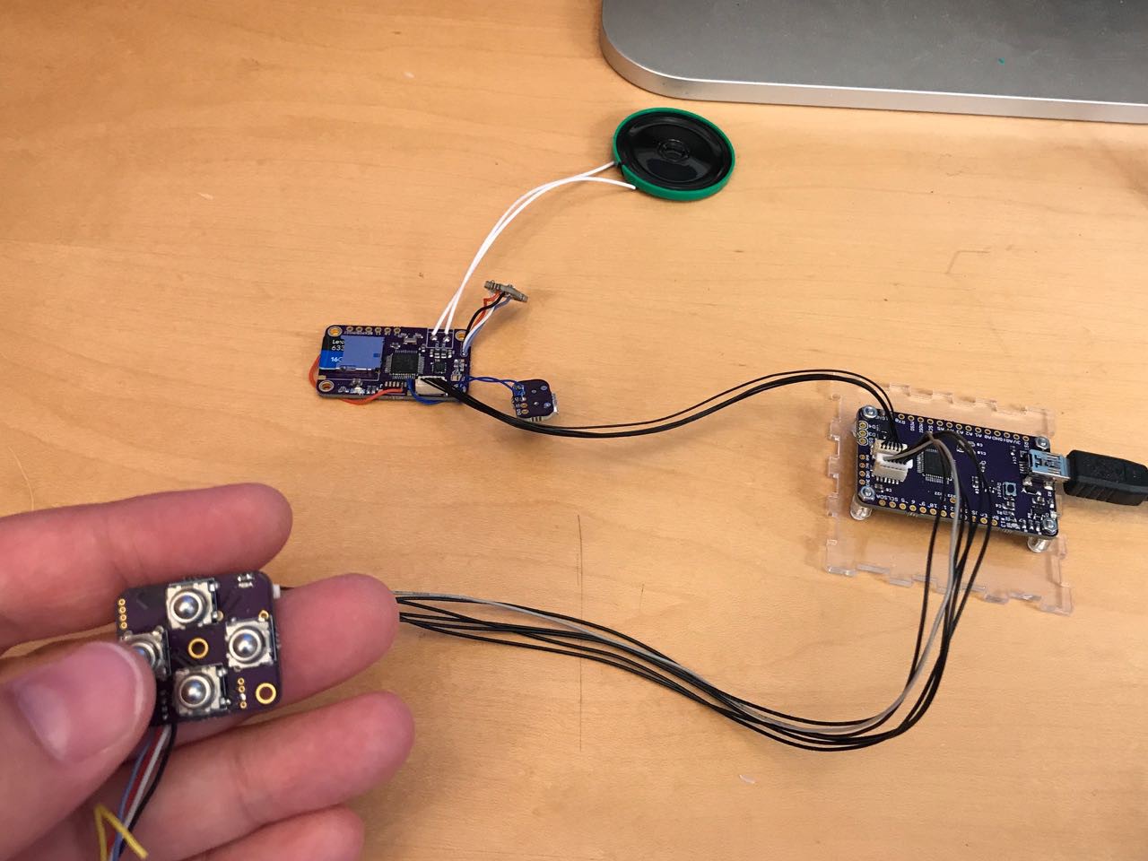
    Using this device inside Makernet code is really easy.

    First you declare an SoundPeripheral object like this:

    SoundPeripheral soundPeripheral;
    The Makernet framework will connect your sound peripheral hardware to this object. Now when you want to play sounds, you can simply call:
    soundPeripheral.triggerSound(1)
    

    By way of a demo, I made a very simple setup with a Makernet mainboard (a SAMD21G/M0), a DPad button and the Sound Board.

    The following code snippet is all you need to have a sound play on a keypress. The Makernet framework handles all of the network discovery, message passing, error handling, etc.

    #include <Makernet.h>
    #include <Wire.h>
    
    SoundPeripheral soundPeripheral;
    DPadPeripheral dPadPeripheral;
    
    void setup() {
      Serial.begin(57600);
      Makernet.begin();
      dPadPeripheral.onButtonPress( buttonHandlerPress );
    }
    
    void buttonHandlerPress( DPadPeripheral *p, uint8_t channel )
    {
      soundPeripheral.triggerSound(55);
    }
    
    void loop() {
     Makernet.loop();
    }

    You can see a quick demo here:

    Writing the code for the Sound Peripheral involved a lot of learning. For the uninitiated, real time sound programming is a bit of an adventure.

    First I had to get the I2S library working properly. The library supports DMA, and you hand it a buffer of things to play periodically.

    Next, I needed to add double buffering, so that sound can be generated in batches and then handed off to the DMA. Otherwise, new sound data generated by the audio sources would trample over old sound data.

    Next, I needed a full audio framework. I started with the PJRC/Teensy libraries that I admire so much. They are brilliantly written, but assume Cortex-M4 DSP instructions which I don't have on the Cortex-M0. Secondly, Paul makes liberal use of a very sophisticated hand-tuned memory library presumably so that each audio source can avoid unnecessary memcopy() calls.

    I ultimately decided it would simply be easiest to implemeny my own library using some of the design patterns I like from the PJRC stuff. In my design, there are a set...

    Read more »

  • Making products is hard - the story of the Rotary Encoder "Problem"

    Jeremy Gilbert06/15/2017 at 21:25 0 comments

    The last 2 weeks have been a big of a slog for Makernet. I'm in that obnoxious phase where a ton of stuff has to get done but there isn't a whole lot of new wiz-bang stuff to show for it.

    It kind of reminds me of this picture:

    Anyway, last weekend I accomplished a major but somewhat unfulfilling task: I successfully stabilized the rotary encoder board's logic.

    The rotary encoder board looks like this:

    I had noticed for a long time that my rotary encoder was not nearly as stable as it is on the Teensy or in other projects I built. I had been treating the Arduino Encoder library as a bit of a black box, but this was coming back to bite me. I was seeing skipped steps and other unexplained repeating pattern glitches. Initially this didn't bother me much because as a proof of concept, it still worked.

    But I'm rapidly getting out of proof of concept mode and quality starts to matter. Over the weekend someone reached out to me on Twitter asking if they could try out some of my boards for a project they are working on. So I now needed to get the rotary encoder far more stable since it would be leaving my workshop and going out into the world.

    I have to admit that I basically never really "grokked" how the rotary encoder works. Yes, I understand the principal, but knowing the theory is quite a bit different than actually intimately understanding the various state transitions. I had been trying to get away with not knowing them and treating them like a black box. But this challenge finally tipped me over the edge since no one on the Teensy forums seemed to have any idea what might be going on.

    So if I wanted a high quality rotary encoder circuit board, basically no one was going to do this for me. I had to do it myself.

    People sometimes say "why do we need Makernet"? For instance, they point out that there is a lot of example code out there for a rotary encoder. Why would a person want to buy (or make from source) a single component that connects a rotary encoder onto a shared network bus? Even if it was less than $10 in parts? Well, one of the reasons is that rotary encoders are harder than they look. They get glitchy!

    In fact, all bits of hardware actually are harder than they look. And if I'm some random interaction designer working on a project where I think it might be nice to experiment with adding a rotary encoder to my device, I don't want to spend a weekend learning the gross details of this esoteric device. Its the same reason why the ArduinoCore is so useful at getting people out of the weeds. Sure, digitalWrite() can be replaced with PORT register calls. But doing that forces you to worry about implementation that you'd rather not have to deal with. It takes your head out of the game and slows down your innovation and your idea generation/iteration.

    Anyway...

    I digress.

    So, the Makernet rotary encoder design needed to be stabilized and de-jittered. After a painful process struggling with my oscilloscope, I decided to try my Saleae Logic 8. This little tool is super useful and frankly probably the most useful diagnostic device I own. After setting up a test rig, I started looking at traces especially under high speed.

    What you see below is both an analog interpretation of the pins as well as the controller echoing back when its interrupt were firing and what the MCU thought the rotary encoders A and B signals were.

    I quickly discovered that there were bizzare corner cases that most rotary encoder code-bases or tutorials don't handle or even bother to tell you about. For instance, the "recommended" way to read an encoder is with an pin change interrupt. But say your encoder is noisy and it bounces around a lot. Its possible that a LOW->HIGH bounce will trigger the interrupt several times, and that by the time the interrupt code reads the pin state it will have temporarily bounced back LOW. That means that for the next few microseconds, maybe longer, the code's state machine thinks that the pin is LOW when its really high.

    This "gap" may...

    Read more »

  • SAMD21 with Makernet - Keypads!

    Jeremy Gilbert06/02/2017 at 20:26 0 comments

    Lots of great stuff going on this weekend, and I'm still cruising off of the huge dose of encouragement I received in the last week!

    First of all, a bunch of new boards came back from OSH Park. The first is a breakout of everything on the ATSAMD21 plus some Makernet headers. This is by far the smallest ATSAMD21 board I have and I'm a bit proud of how compact it is. It reminds me a lot of the Teensy 3.0 boards.

    I plan to use this board to prototype keypad interfaces. The idea is to make an adapter board you can connect to any keypad and get it onto Makernet easily. Keypads are annoying to wire into a project because they need a lot of GPIO pins and thus a lot of messy wires in your project.

    I have a bunch of keypads in my collection:


    While most of these keyboards are polite, only needing ~8 pins, some others are not so elegant and have a pin per key.

    And then there are some boards like this one I ripped out of a graphics test pattern generator I bought at MIT swapfest:

    This board, while very cool, needs 20 pins for reasons I haven't fully investigated.

  • Communication, communication, communication

    Jeremy Gilbert04/25/2017 at 12:48 0 comments

    I spent the weekend shooting some video with my daughter to try to better illustrate my Makernet idea.My daughter wanted a timer for her toy rocket that would give a countdown. She wanted colors that would go green when it was time to launch.

    What a perfect opportunity!

    Here is the rough sketch:

    Next, I built a full implementation with a breadboard. Lots of messy wires, and the project isn't very shareable. Even with plenty of rehearsal, I still managed to screw up the wiring three times on the video.

    Finally, I built the same project using the prototype Makernet modules I had made so far:

  • More devices

    Jeremy Gilbert04/25/2017 at 12:13 0 comments

    GM1201 - Metal ball tactile DPad

    The second I saw these cool metal buttons on Adafruit, I knew they had to be part of my Makernet user interface. This DPad is a four way controller featuring four directional buttons. Cute, eh? They are super clicky when pressed - extremely satisfying.

    Unfortunately, this DPad module presented a lot of unexpected challenges. Unlike the other modules I had built, this one had some unexpected clock issues that exposed some serious gaps in my understanding.

    I first realized something was wrong when the serial port on the board was garbled. By way of explanation, my standard test jig involves GND, VCC, SWD, SWC and a TX UART pin. When I loaded the test firmware initially, the status messages printed to the UART at 115200 baud were garbled. At first, I suspected that I had somehow screwed up the SERCOM UART configuration, but loading identical firmware onto the rotary encoder board (GM1200) didn't show this problem. So it was a problem with the board, not the code.

    I suspected that there was a short or some wiring issue, but i couldn't find any obvious reflection or inductance probing around with a scope. Granted, I am fairly witless when it comes to analog signal debugging so I may not have even been using the scope properly to do this. Next, I inferred that a slower baud rate would be more impervious to noise, but even running at 1200 baud still showed the problem.

    After wracking my brain, I finally concluded that perhaps the clock on this particular copy of the chip might not be as stable as the other board. ARM clocks are notoriously complex and arcane. The SAMD architecture has 7 different clock generators that can be routed to nearly any purpose. For instance, you can clock your chip UART one way, and you peripheral bus another way, and your actual processor a third way. You can even use one clock to drive another clock in a phase locked loop.

    What is supposed to happen on the SAMD11 architecture is that your code starts running at a very slow, baseline 1MHrz speed using a very unstable boot-up clock. It has all sorts of jitter but its supposed to be enough to get you going. The first thing your program code is supposed to do is set up a proper clock configuration. Typically you configure two pins to be XTAL inputs, and connect those to a 32Khz crystal. 32Khz is really slow, right? So something called a digital phased-locked loop is used to "step up" the speed to 48Mhrz. Not being a signal expert, I am a bit at a loss to explain how it works but my basic guess is that the DPLL is a much less stable but faster oscillator that is more sensitive to noise and the environment. The 32Khz signal is used as a reference heartbeat, and the circuitry must alter the speed of the DPLL to match the heartbeat, thus guaranteeing a consistent clock.

    In my architecture, I don't want an external clock or crystal. Fortunately, the Atmel chip designers included a high precision 32K internal clock, presumably one based on a RC oscillator. This clock is factory calibrated. I had hoped this would be sufficient for all of my Makernet peripherals.

    Given that the serial port didn't work with the internal clock, I was tempted to assume my factory calibration was off. I seriously considered just pulling the chip off and substituting for another copy. But my experience so far on this project has taught me the value of double checking my assumptions. I've noticed that if I force myself to learn how to debug something with the right tools and instruments, I'll gain much more insight and avoid more mistakes and frustration later.

    The first tool I reached for was a Bitscope Micro. This little baby is supposed to work as a logic probe and an oscilloscope. However, over the past year, I have rapidly came to loathe it as an oscilloscope. On the other hand, the Bitscope supports a logic probe. I was eager to try it out and redeem my $129 purchase. But I rapidly discovered how sucky the software is. Slow and sluggish. I needed to calculate...

    Read more »

  • First Makernet Boards: An RGB Rotary Encoder

    Jeremy Gilbert04/20/2017 at 21:20 2 comments

    Hot off the press are two new Makernet boards. This post will talk about GM1200, a rotary encoder module.

    Firmware for my boards is still in a very early state but a lot is working. Each module participates on the Makernet bus and performs some input or output function for the user's project. Each peripheral runs controlling firmware on a 48Mhrz ARM processor that supports network arbitration, addressing, broadcasting, event polling, and imperative commands. The event architecture reduces the need for polling - only devices with new information to share to the MCU raise their hand to send events. The ARM is internally clocked and doesn't need an external crystal.

    I've decided to give each module a product number to help me look them up quickly in my notes and identify hardware versions.

    GM1200 - Rotary Encoder 1.0

    Every project needs a rotary encoder - not only are they fun to twiddle, but they are great for menu navigation, setting values and all sorts of other useful things. This module drives a single rotary encoder which includes a pushbutton switch and a RGB LED. It also sports a small activity LED on the side to tell you if the module is working. Attractive, don't you think?

    The backside supports two Makernet ports, so the knob can be daisy chained with other peripherals. Everything is controlled with a 48Mhrz Atmel SAMD11 ARM chip running at 48Mhrz. The LEDs can be PWM'ed to any desired brightness. The chip uses interrupts to process grey code from the rotary encoder to reduce the chance that steps are missed.

    The initial batch of these worked nearly out of the box, however, there are a few planned improvements. First, I want to standardize on a 0804 LED indicator. Secondly, I neglected to put in I2C pull-ups, which I think are probably essential. There is an empty space for a clock and capacitors that ended up not being required once I got the clock-less configuration working. Finally, I haven't made a firm decision if the rotary encoder actually needs debouncing capacitors so those spots are un

  • March Update (late)

    Jeremy Gilbert04/19/2017 at 21:37 0 comments

    For the May deadline, my current aim is a demonstration project - a vivid illustration of how someone could create a variety of different cool looking, functional projects, using the Makernet architecture. I am hoping to do this with a combination of videos and code examples.

    Why something demo-able? I think it will make the idea of Makernet come alive much better.

    This means I'll need a few different things:

    • Some kind of controller board (e.g. where the user puts their code). Has to be Arduino IDE compatible and have the Makernet hardware support on the PCB.
    • A common design for each Makernet peripheral, each ideally reprogrammable using the Arduino IDE, with as much consistency as possible in design.
    • A variety of actual Makernet peripherals built on the common design standard. I am aiming for a rotary encoder, a D-pad, a 128x64 B/W OLED, 8x8 mini LED matrix, 8x8 large matrix, and a sound generating board.
    • A good way to photograph and create videos of my work

    Over the last few months I've been putting together all of the fundamentals needed for the demonstration project. Some key accomplishments between Jan-March:

    - Interviews with a number of makers around the boston area to help learn what niches Makernet might address

    - Leveling up my soldering skills to repeatably solder the 24-QFN and 1mm fine-pitch connectors needed in the project

    - Creating a miniature SWD programming header (G/V/D/C) so that the ascetics of my boards will be as clean as possible

    - Creating a simple programming jig with tiny pogo pins (1.27mm pitch, for the win!)

    - Building out an Eagle library for the key parts I'll need so I can have standard looking resistors, capacitors, PTH connectors, logos, etc.

    - Settling on JST-SH as the board-to-board connector standard and working out a temporary source for the cables I'll need. Digikey offers these cables, but they are 1-to-N not 1-to-1. (Booo!) I will have to manually reverse them. For those not aware, JST-SH is a 1mm pitch connector -- reversing these cables will require work using a SMT inspection scope.

    - Building some test boards using the Atmel SAMD11 MCU to see if I can get the platform working on my build environment, and to evaluate the state of the Arduino Core for this platform. Turns out Justin Mattair has spent time porting the Arduino code to the SAMD11. These tests went very well, and I was able to get all of the basic things I need - analog, digital, PWM, in a fairly portable format. This allows me to feel confident in standardizing all of my Makernet peripherals around the ATSAMD11.

    - Taking a deep tour through the ATSAMD11 Arduino Code to figure out how remap pins the way I want them. This will let me cut down on BOM and layout complexity for the peripherals.

    - A massive adventure with the black magic of ARM clock configuration code to load factory calibration into the various internal oscillators. This will get me standalone ARM processor with very little external logic that will use a high accuracy internal clock.

    - Creating a Makernet clone of the Adafruit Feather M0 (ATSAMD21G18-based MCU) which is one of the candidates for my controller boards.

    - Creating a working Teensy 3.2 clone which is another candidate for the the central controller board design. The Kenisis MCU is much more featured than the SAMD21, with better instructions. Also, I'd argue that Paul supports it much better than any Arduino, and it has a clearly thriving community. I'd love the Teensy to be the central architecture given its excellent libraries and my admiration for the team that supports it.

  • Concept origins

    Jeremy Gilbert04/13/2017 at 20:40 0 comments

    In this post, I want to share a bit of the origins of the Makernet idea. In the next post I'll talk more about where I am today.

    By way of background, I've been a "maker" since 2012, when my daughter was born. Prior to that, I was a software engineer turned management consultant. I guess I was destined to re-enter the making world. On one fall day in 2012, I walked in a Radio Shack and on a whim, bought my first Arduino. That afternoon, I blew the dust off of 15 years of unused EE training and got hello world up and running.

    The idea of Makernet started a few years later in my re-entry to "maker" hood. My daughter was about one year old, and I built her an electronics toy. I made it out of crudely glued plexiglass with a AT328P and a simple program that made light and sound when she pressed a knob. I wanted her to have something she could play with where the internals and electronic guts were visible. (The transparent case was critical - I wanted her to feel her electronics toys were understandable not mysterious.)

    Picture below: My first standalone project (since 1998).

    The project required a rotary encoder, and I had limited experience with this type of device. I hacked the module onto a slab of blank perf-board just above the MCU. Too late, I discovered that the pins I had used did not support the right kind of interrupts for grey code. More rework. Uhhg.

    Rotary encoder knobs are cool. They are so fun to twiddle, especially if your project does cool things with lights and sounds. Every project should have one. But what a pain to integrate! You have to deal with interrupts, with a state change and a ton of other things.

    There and then, I resolved to someday just create a simple I2C rotary encoder module. Then adding a rotary encoder to any new project would be as simple as adding an I2C device to the bus.

    Fast forward a few years, and I was building the box of clicky awesomeness. It has at least 6 I2C devices inside: an accelerometer, gyro, magnetometer, hepatic driver, capacitive touch sensor, etc. Two devices had to have I2C addresses reassigned. The wiring was a complete mess. The project barely fits in its case due to all of the obnoxious bits of glue logic. But the project was a success - on Cambridge Hackspace open houses, people love sitting down and playing with it.

    This is what it looks like:

    How to make things more modular? At this point, I had been building quadcopter using the DJI Naza platform and I was familiar with the elegance of CANBUS. The DJI autopilot platforms communicates with everything over CAN - the GPS, bluetooth, gimbal control, etc. Its dead simple to rearrange your drone because you don't have a ton of point to point wiring.

    I became determined to make the same level of flexibility and interchangeability available to Makers. I built an early pitch deck and researched I2C and CAN to try to decide what technology to standardize on. I2C is limited - it doesn't support flexible addressing and its not clear how long the bus can really be. It doesn't seem ideal. And CAN is obnoxious - it needs relatively expensive 5V logic transceivers and the protocol is complex. In most cases, you need to select a specialty MCU that has a hardware implementation for the CAN protocol.

    Then I discovered RS-485. The transceivers are relatively inexpensive. Combining RS485 with a $1.00 ARM MCU, you'd have the foundation of a network bus for maker projects. And you get the resilience of

    At this point, I started sharing the idea around my local hackspace. Someone quickly pointed me towards a platform called Modulo. I reached out to Erin Tomas, the inventor of Modulo. She had a very similar idea and created a whole line of modular units that she now sells online. The idea is that each module is a simple sled that fits into a docking station. One of the modules is the main controller, and the rest act as I2C slaves. She has a library of about 10 different modules that can fit into the docking station.

    Her vision is to enable plug-and-play...

    Read more »

  • First post

    Jeremy Gilbert04/13/2017 at 13:36 0 comments

    Wow, OK, here it is, my first post about Makernet. The last four months have been a busy blur with my day job plus my Makernet hacking work crammed in between. I am remiss in keeping this journal up to date and even explaining to anyone out there what the idea is about.

    The goal of Makernet is simple: Democratize the creation of projects where the increase in hardware complexity creates sub-linear increases in complexity. Or in laymen terms, adding more stuff to your project should be easy, transparent and modular. The result will be faster learning for new makers, because it makes hardware look and act more like the software paradigms they are already used to in their daily life.

    Wow. OK. So what do I mean by that?

    I want hardware projects to act more like software projects where there are libraries of interchangeable parts with clean abstraction barriers, substitutability, and clean APIs.

    You want to swap out your rotary encoder scrolling interface for a touch-based one? That should be a snap. A 10 minute job.

    You want to refactor your project case to sit on your desk rather than your shelf? That should be easy. 30 minutes or less.

    Here's the challenge -- for many reasons, hardware engineers don't typically think about clean lines of abstraction and modularity. They often cant - a OLED display needs extra control lines and and SPI interface. A rotary encoder needs to be on interrupt generating pins. There are tons of wired dependencies that take hours to understand and grapple with. So the typical project has multiple design layers: the physical layout of the project, the PCB layout, the circuit design and finally the code design. All of these different things become hopelessly tangled together. You want to experiment with a different user interface for your project? Or add a new peripheral? In many cases, you end up re-designing half of your project! So you end up with cascading complexity when you start adding new things.

    This is not how pure software works. In pure software, you pick really good abstraction layers that keep one part of your project from touching other parts. CSS keeps your styling separate from your rendering code. React keeps your UI logic separate from your back-end. I'm not saying web technology isn't complex, but we've done so much to iron it out and smooth it down to clean borders.

    I want to help do this for hardware makers. Especially young, up-and-coming makers.

    I want to meaningfully make it easier for the average hardware builder to benefit from modularity of the components they use, and the software they use to talk to their hardware.

    So why is this good for the world?

    In short, I think it will transform the way people learn about and understand electronics. Young makers are exposed to computers and software early in life. They use Minecraft. They tinker with legos. The use USB to plug in new webcams. They expect their world to be rearrangeable using software-like principals. Hardware in its current form will seem archaic, like a weird throwback. Things like I2C address conflicts, and the hardware internals of PWM are great to understand eventually, but should not be a major consideration for new makers.

    In my view, early makers should be exposed to simple combinations of hardware and software that they can tinker with and earn fast results. They should be able to start building things that resemble the world around them quickly. And they should be insulated from complexity until they are ready to dive into it. They should stay frustrated enough that they have to learn and it doesn't come too easy, but not so frustrated that they half to walk away from projects they think and known ought to be simple.

    I also fundamentally believe that projects should be shareable. If my daughter builds a cool little project that glows different colors based on the temperature, she should be able to take it with her. She should be able to show it to her class, or take it on a play date. It should fit into her pocket. Sharability...

    Read more »

View all 10 project logs

Enjoy this project?

Share

Discussions

Bartosz wrote 08/27/2017 at 08:51 point

1. Please add Lora network similar gotenna.com or sonnet

look at cc1101 procesor

2. change connection. in my opinion rj45 is better than normal wired. why not using normal rj45 or smalest for old phones to connect power and i2c ?

  Are you sure? yes | no

Morning.Star wrote 05/04/2017 at 07:20 point

Hi Jeremy :-)

After discussion with the guys, I think we'd be very interested in some kind of symbiosis. The more complicated Cardware gets, the more trouble we have with cabling. Distributive architecture was the immediate solution, and I've got in mind a network of ATTinys or similar on a ring token style packetised serial loop - daisy chaining the Tx to the Rx of each. This would need just 4 wires between modules (V+, Gnd, Tx, Rx), and just the power if we used IR repeaters in the joints.

The reason for this is twofold - one is Cardware's architecture is dynamic, limbs are replaceable and upgradeable, and it would be nice to have damage sensing - simply unplug the broken part and the OS senses and adapts to its configuration. I've also recently discovered the delights of WiFi ESP SOC devices...

It seems what you're doing is remarkably similar if we can get around the wireless comms. If you're interested in developing that side of your system we could perhaps join each other's projects?

Jez #Cardware

  Are you sure? yes | no

Jeremy Gilbert wrote 05/07/2017 at 21:57 point

Hi Jez -would be great to work on this together. Would it make sense to connect offline (maybe a screen share) and talk through? I'm not sure I've fully had a chance to grok your project.

In principal the Makernet protocol would work over IR or RF and I'm starting to do some tests to see how well that might work. I'd be happy to send over some pre-release code for you to look at. I believe it will also work on a one-wire RS485-like implementation, so that would save you one wire. The RFM69 wireless modules are nice but they are big -- 16mm x 20mm. 

For MCU, I'm standardizing on ATSAMD11 which I think is cheaper than ATTiny (with more memory) but is Arduino IDE compatible and also made by Atmel/Microchip. It should support PWM and its very small with almost zero external passives needed. 

  Are you sure? yes | no

Morning.Star wrote 05/10/2017 at 07:21 point

Hi Jeremy.

Apologies, I only just got around to checking back - I missed your reply in the feed for some reason. I've had flu and not really done much for a couple of days.

I'll do some research and PM you later today. It now looks like I'm going to need a power coupling designed into the joint mechanism. If this works like I'm hoping, limb parts will be less plug-and-play and more living Lego bricks, but I'll explain more later.

I like the Atmel architecture, although I havent played with any of the newer devices like SAMD. I also like cheap, and I cant build *every*thing out of cardboard and tinfoil...

  Are you sure? yes | no

Daniel Dunn wrote 05/02/2017 at 21:23 point

I really like this idea, it's disappointing there isn't more modularity in this kind of thing.

What if you made power transmission modular too? If you require a diode on every power supplying device for reverse current protection, you could have multiple power supplies, but you would lose a few percent of the energy in the diode drop.

You would probably also need a polyfuse on every connection, because for hub-like devices you wouldn't know in advance what's a supply and what's a load, and some might even charge from Vin and supply on 3.3

  Are you sure? yes | no

Jeremy Gilbert wrote 05/03/2017 at 19:45 point

Interesting observation. Frankly, I haven't gotten that far in the design to have a definitive answer. Right now a single node provides the power to the other nodes. There are power management ICs that may serve that purpose that will have less loss.  I'll have to research how to handle that. In general, i'm going for something that can go into a sleep mode and consume < 10uA. 

  Are you sure? yes | no

Morning.Star wrote 04/29/2017 at 10:41 point

Hi I'm sorry we didnt get a chance to speak in HackChat. When it gets busy, the interface is too slow to type in... I may have appeared a little terse in my choice of words.

My point was that although MakerNet is a good idea (I've also noticed how modular the architecture has become) it means purchasing lots of little boards. This makes it proprietary in nature and also locks the students into a knowledge path. There isn't anything wrong with I2C, or indeed a protocol you've written yourself (I applaud your use of a wide standard here), but it doesnt teach how an MCU addresses the various hardware, for example, it simply replaces it with a layer.

Abstraction is all very well, but it created Microsoft and the problems monolithic systems are causing in education now. This is why I have utilised cardboard as a substrate in my work - it becomes a framework for knowledge rather than a series of modules replacing it.

Your approach is very different to mine, but I wish you the best of luck all the same :-)

  Are you sure? yes | no

Jeremy Gilbert wrote 05/03/2017 at 19:43 point

Great points. We think alike. I think its worth splitting out the education objectives. In the case you are trying to teach people how EE works on the inside, I fully agree you need to start with things like Arduinos or even just analog electronics. In the case you are trying to teach people to love EE, I'm more worried about inspiring them than I am about the simplicity. Legos teaches people to think about construction, even if it simplifies a vast amount of knowledge about friction, tensors, material properties, etc. And if everything is open source, no one will feel locked in. 

I actually do think that in the future more and more complex devices will be build with field buses. The fact that I can effectively buy a MCU, network controller, network interface in one package for $1.00 changes the game. 

I'm hoping dozens of people make their own makernet devices and we can get a whole community going of people who build their projects this way. :)

  Are you sure? yes | no

davedarko wrote 04/28/2017 at 21:18 point

isn't it just ATSAMD21G18 instead of AT91SAMD21G18?

  Are you sure? yes | no

Jeremy Gilbert wrote 05/01/2017 at 10:50 point

Yup! Thanks!

  Are you sure? yes | no

Jeremy Gilbert wrote 04/28/2017 at 19:57 point

Thanks for the comment and sorry I didn't see it earlier. I started with I2C because my aim right now is to test the idea and see if it resonates with other people. I defined minimal viable product the minimum that would show the excitement of the concept to others and validate my putting more effort against it. I2C is a hack that lets me mix makernet and non-makernet enabled devices for the proof of concept. In the end, I will probably either switch to RS485 or make some sort of repeater since I2C is working remarkably well.

The six wires are: GND, 3.3V, VIN (4-5V), SIG (reserved for future), SDA, and SCL. It could easily be pared to 4 wires as you suggest.

"Asynchronous" signaling is handled by a clever hack of the i2C bus I learned from Erin Tomson at Modulo. In my twist on her design, all of the devices sit on a common I2C bus address (address 0x09.) The master sends out broadcasts allowing each device to raise their hand with a message. I2C arbitration is used to avoid bus contention.

I2C is a clocked protocol so variation in the processor speed of each module isn't relevant. My experience so far is that 115kBaud is stable without the crystal, so there should be a way to get RS485 working there too. The internal RC oscillator is calibrated at the factory.

The protocol will obviously get documented if I proceed with the project. Right now, its all documented in header files. :)

  Are you sure? yes | no

Morning.Star wrote 04/29/2017 at 10:57 point

I would myself stick with I2C as the standard, the point of being able to mix non-MakerNet devices is really a feature I'd not wish to lose. There are a lot of I2C devices out there already... Now if you could do this wirelessly over very short range instead of a wired protocol you would have a killer.

Cardware is hollow and has room for Special Weapons and other modifications, but wiring is a pain. We've discussed this in team chat and come to the conclusion that smart modules with wired power and a common wireless bus would be the answer. If you ever do something like this, we'd be very interested in it.

  Are you sure? yes | no

Jeremy Gilbert wrote 05/01/2017 at 10:48 point

Interesting idea. Cardware is very cool btw - just followed the project!

I have experience using the RFM69 modules for self-organizing networks.. they work pretty well and they are pretty cheap. They would also be compatible with the Makernet protocol which can easily be adapted to wireless and unreliable transports. But I'm worried the RFM modules might be too bulky for Cardware and I'm not aware of a smaller module. Is it viable for you guys to run a third wire as an open-drain communication channel? If you did that, we could really get cooking -- I have a prototype of Makernet that works on 3 wires: Power, GND and Comm. And you'd still get the daisy chain ability.  Happy to talk more about this!

  Are you sure? yes | no

Frank Buss wrote 04/22/2017 at 22:56 point

Looks interesting. But why first I2C and later RS485 and not starting right away with RS485? And do you have a description of the 6 wires for your connection and the protocol? How do you do asynchronous signalling and how does it work with RS485 with ARM microcontrollers without a crystal?

I thought of such a bus, too, but it would need only 4 wires, and no crystal required, because the first byte (or few bytes) of each package would be the sync byte for the auto-baud calibration of a PIC chip.

  Are you sure? yes | no

Similar Projects

Does this project spark your interest?

Become a member to follow this project and never miss any updates