0%
0%
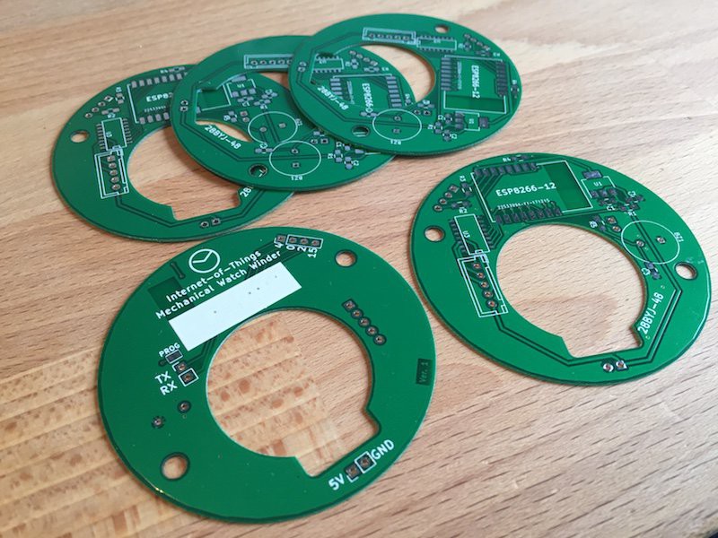
IoT Mechanical Watch Winder
To solve the age-old first-world-problem of having too many automatic mechanical watches, configurable from a smartphone!
Become a Hackaday.io member
Already have an account? Log in.
Just one more thing
To make the experience fit your profile, pick a username and tell us what interests you.
Pick an awesome username
hackaday.io/
Your profile's URL: hackaday.io/username. Max 25 alphanumeric characters.
Pick a few interests
Projects that share your interests
People that share your interests

 Jeroen Delcour
 Vijay
Vijay
 Adam Fabio
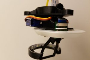
 Daren Schwenke
Great project.
I know this is an old project, but is it possible to get the schematics/wiring diagram and BOM for the electronics? I have a similar watch winder already printed and would like to be able to control it through a web interface.