 Jakub Kaderka
Introduction
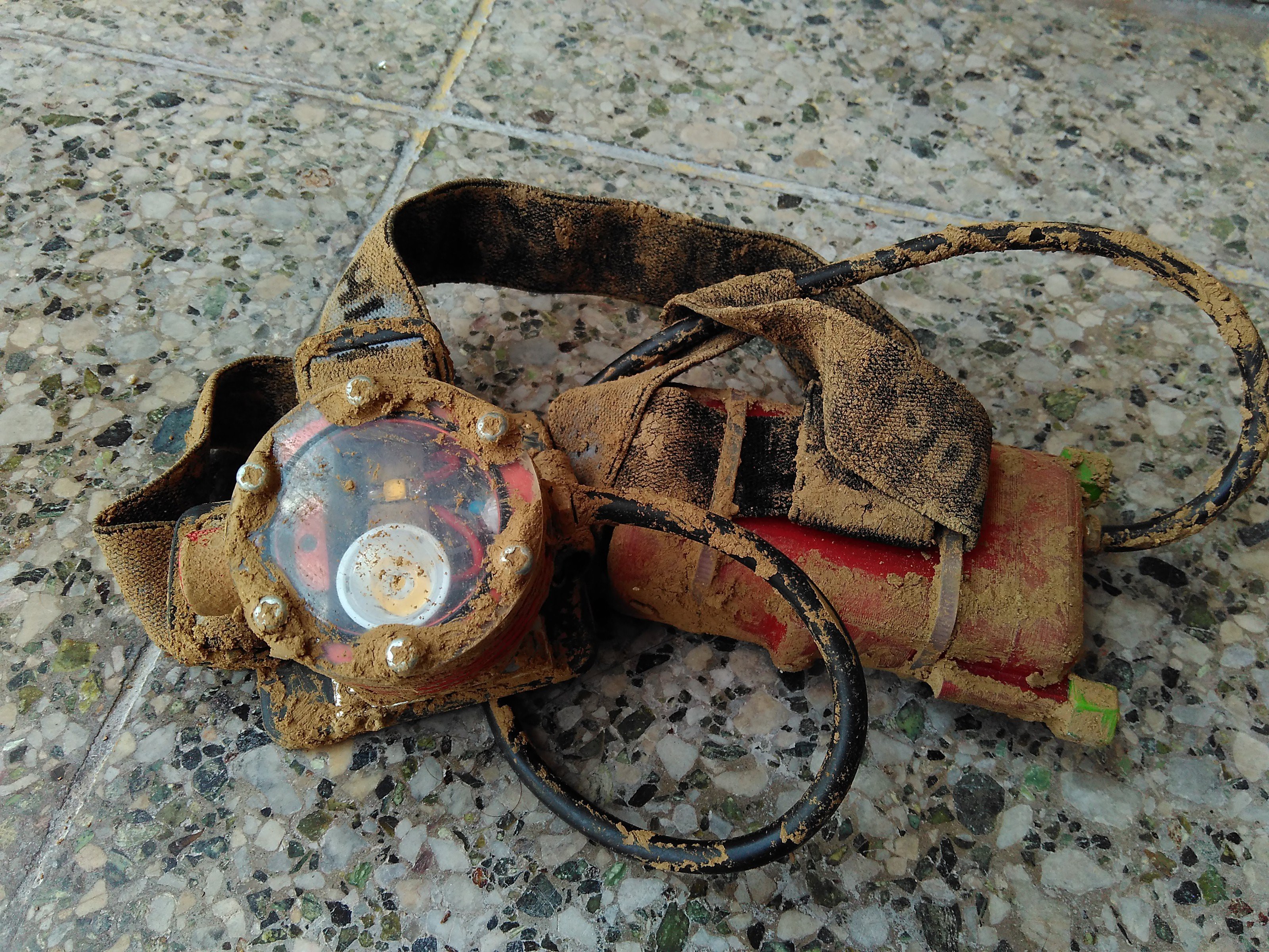
After few trips to caves - and I mean the cave as the nature created them, no concrete walkways, just the mud and narrow passages - I was hooked. In the natural darkness, your life depends on light. No light, no safe way out. These 5$ headlamps with "fire" in their names from ebay are not the best choice and professional lamps like Scurion are quite expensive. So? Let's make custom headlamp!
What I need from the headlamp:
- Mud/water/shock/bomb proof casing.
- Long burntimes with reasonable light output.
- High power mode for photography and large areas.
- High efficiency.
- Reasonable CRI and warmish color temperature.
- Wide range of output power.
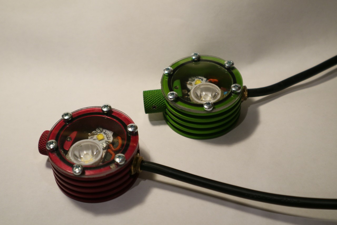
- Flood and spot LED.
- Thermal and low voltage limits.
- Reasonably low-cost.
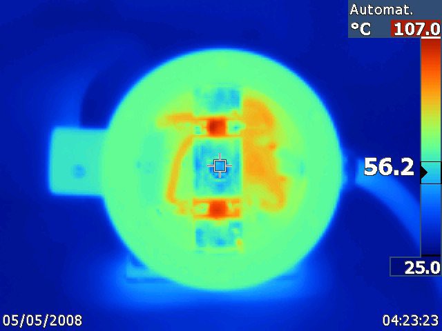
After the first iteration I was still not satisfied. Cooling through vias under LEDs was insufficient, going over 200 lumens was complicated, the custom LED driver based on PIC MCU internal comparator was far from being effective,... So here comes the new iteration!
LED driver
Newest Cree XP-L2 LED can go up to 3 A (or more if you are crazy enough), most low voltage LED drivers can't run on such currents and these that can won't work below 4 volts or so. Therefore I designed custom buck driver that can work on single 18650 Li-Ion with currents over 2 amps (higher currents can be reached by replacing coil and MOSFET for higher power alternatives).
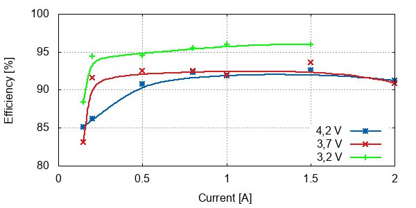
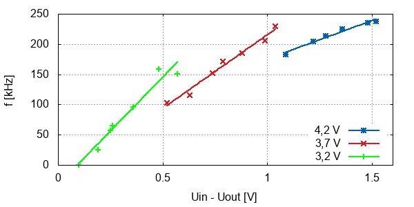
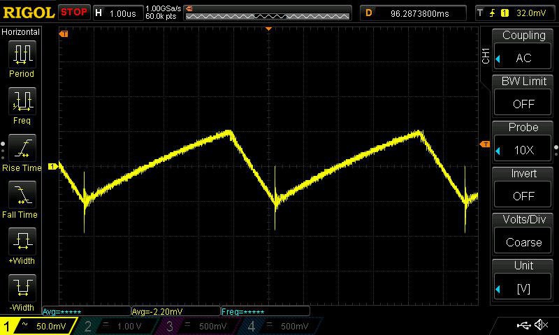
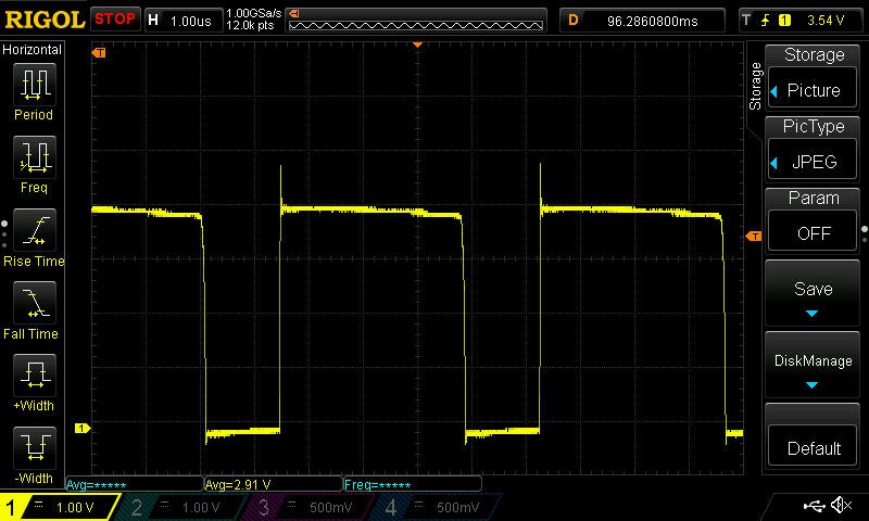
It's hystersis driven buck converter with current feedback. The current is sensed on 0,056 ohm resistor, voltage across this resistor is amplified by opamp and fed to the comparator. The comparator is brain of the driver. When the measured voltage is higher than reference voltage generated by MCU, it turn's the MOSFET off, current drops below hystersis, MOSFET is turned on again and the cycle starts again. Nothing fancy, but quite simple. Only few parts are required and measured efficiency is reaching 96 % (when battery voltage is close to output voltage, average efficiency is around 90 %).
One disadvantage of such design is limited lowest possible current, it can't go below half of the hystersis current. So for this reason 10-100 % output is constant current, 0-10 % is dimmed by PWM.
Controls
The lamp is controlled by attiny 841. It generates two PWM signals which are fed to RC filter to get a DC voltage reference for two LED drivers.
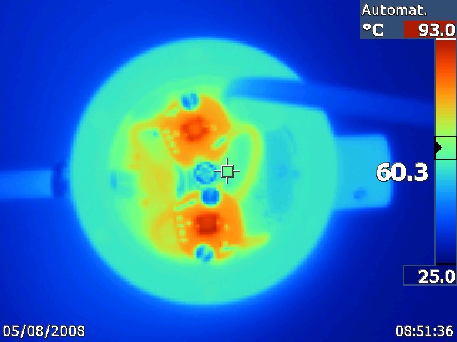
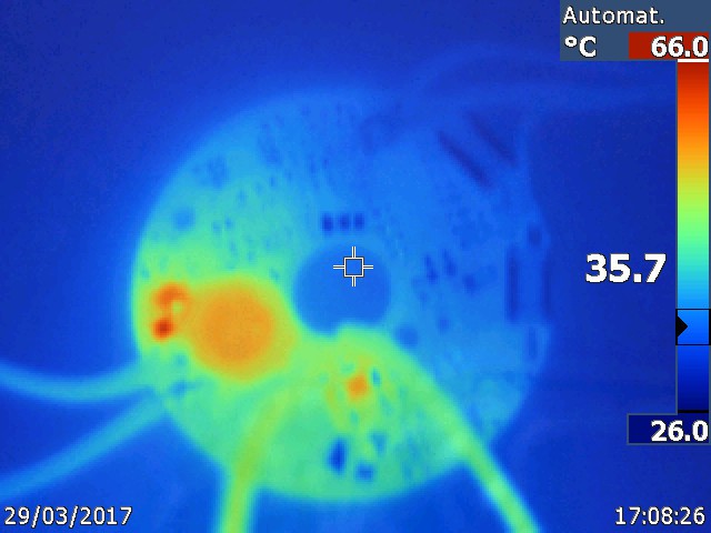
The MCU is taking care of low voltage and overheating, when certain limits are reached, the output power is limited. When the battery is almost flat, the lamp switches to low power mode that can run for few more hours.
I'm also experimenting with automated light control based on reflected light. The light is measured by phototransistor and processed through PID regulator. It works quite nice on very short distances, but the sensitivity is too low for real use so far as the phototransistor is buried at the bottom of the lamp and only a tiny fraction of reflected light can reach it.
I'm using optiboot bootloader, but the code itself is completely arduino-free. No arduiono libraries were used, just the pure avr-glibc and custom makefile. To make it a bit friendly to other programmers, the hardware control routines form a simple API. To write a custom control mode only basic C knowledge is required, no need to touch hw directly. The API will provide programmer with button states, time of button press/release, light control in 255 steps for each high power LED, etc.
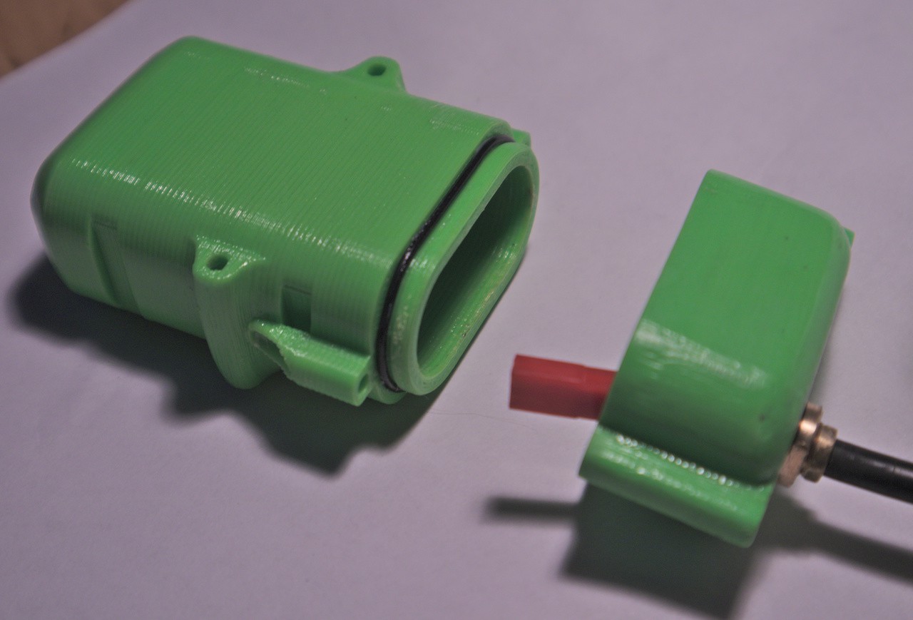
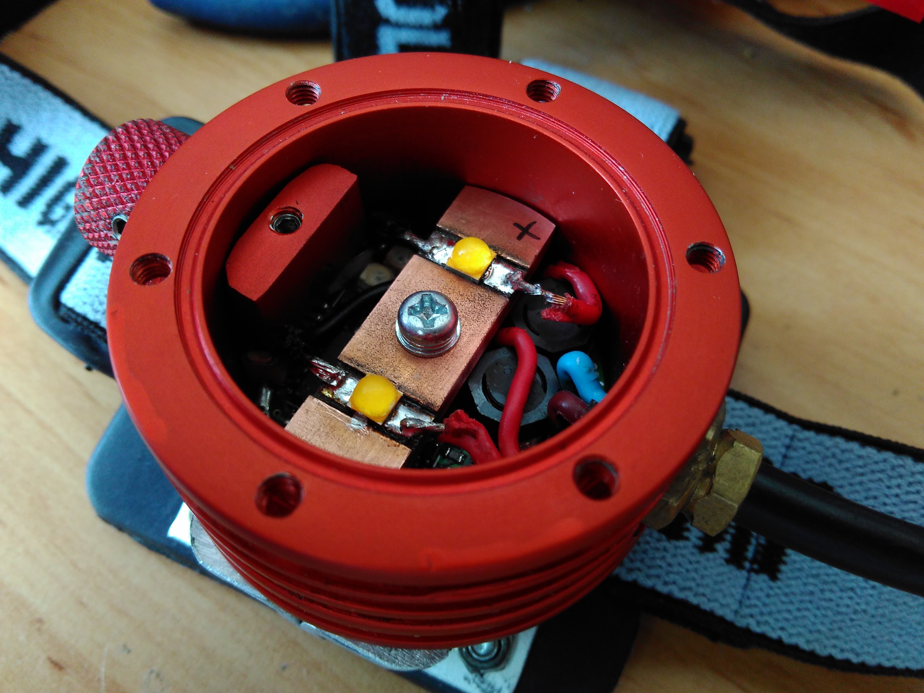
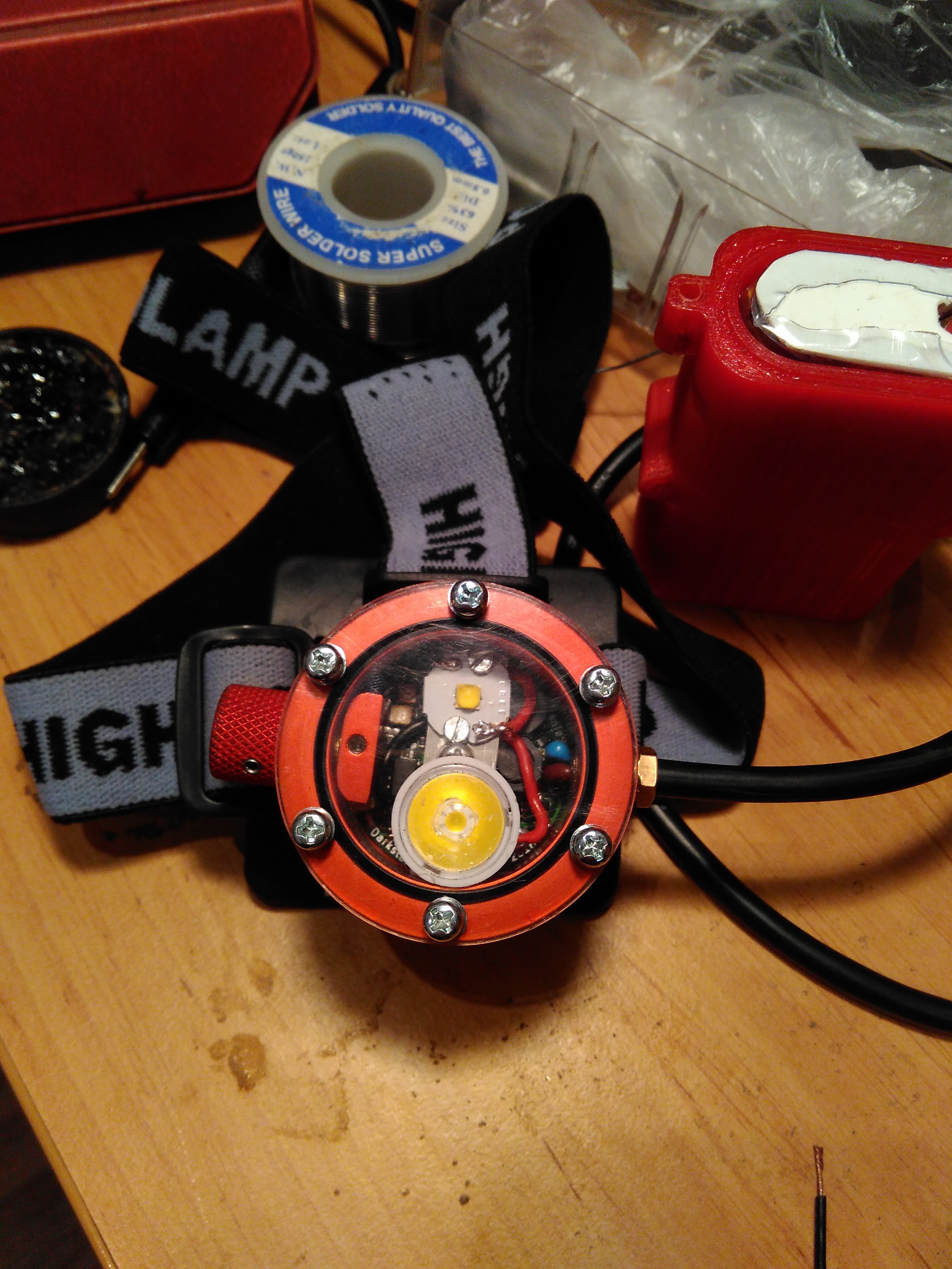
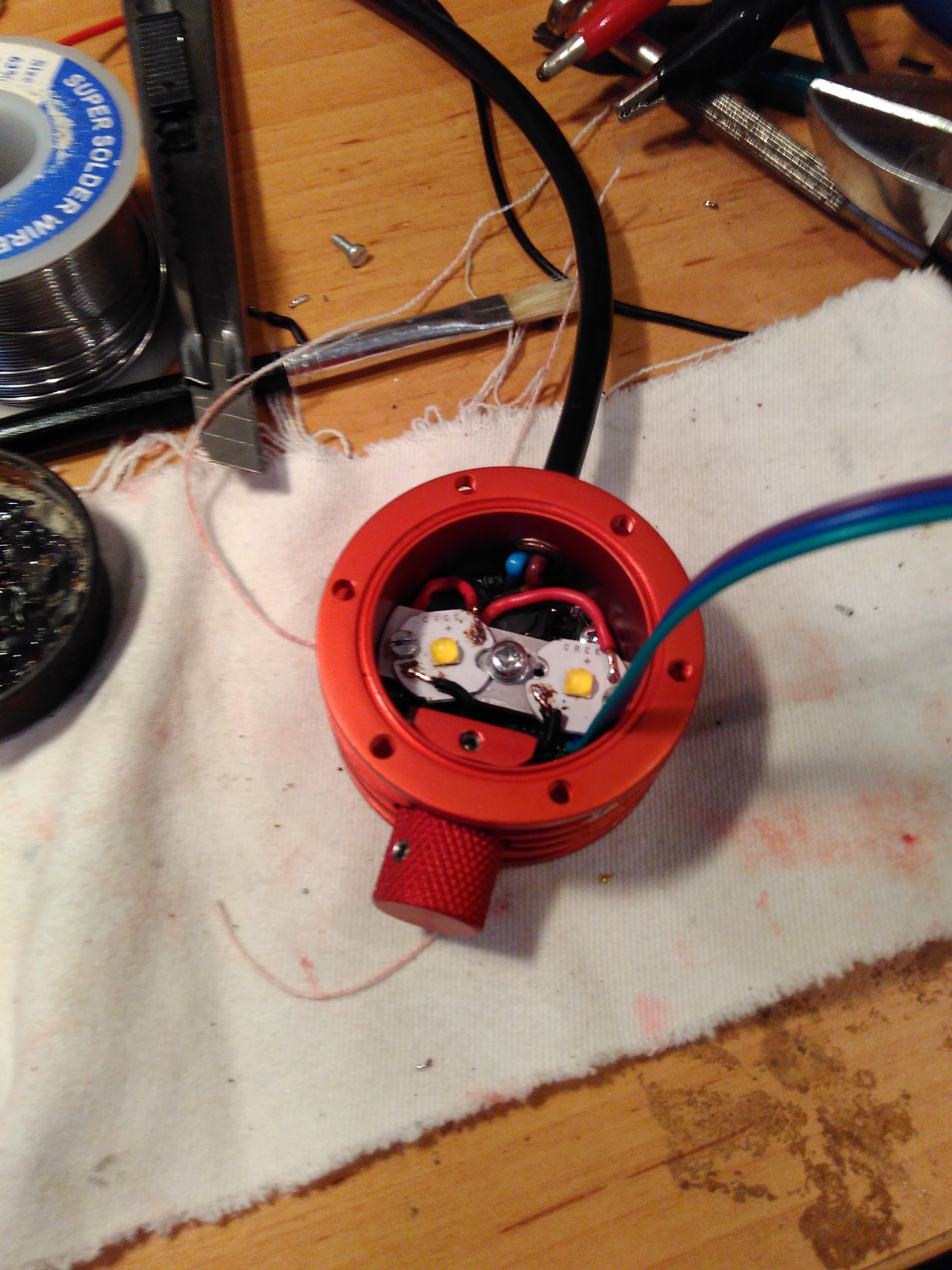
Mechanical
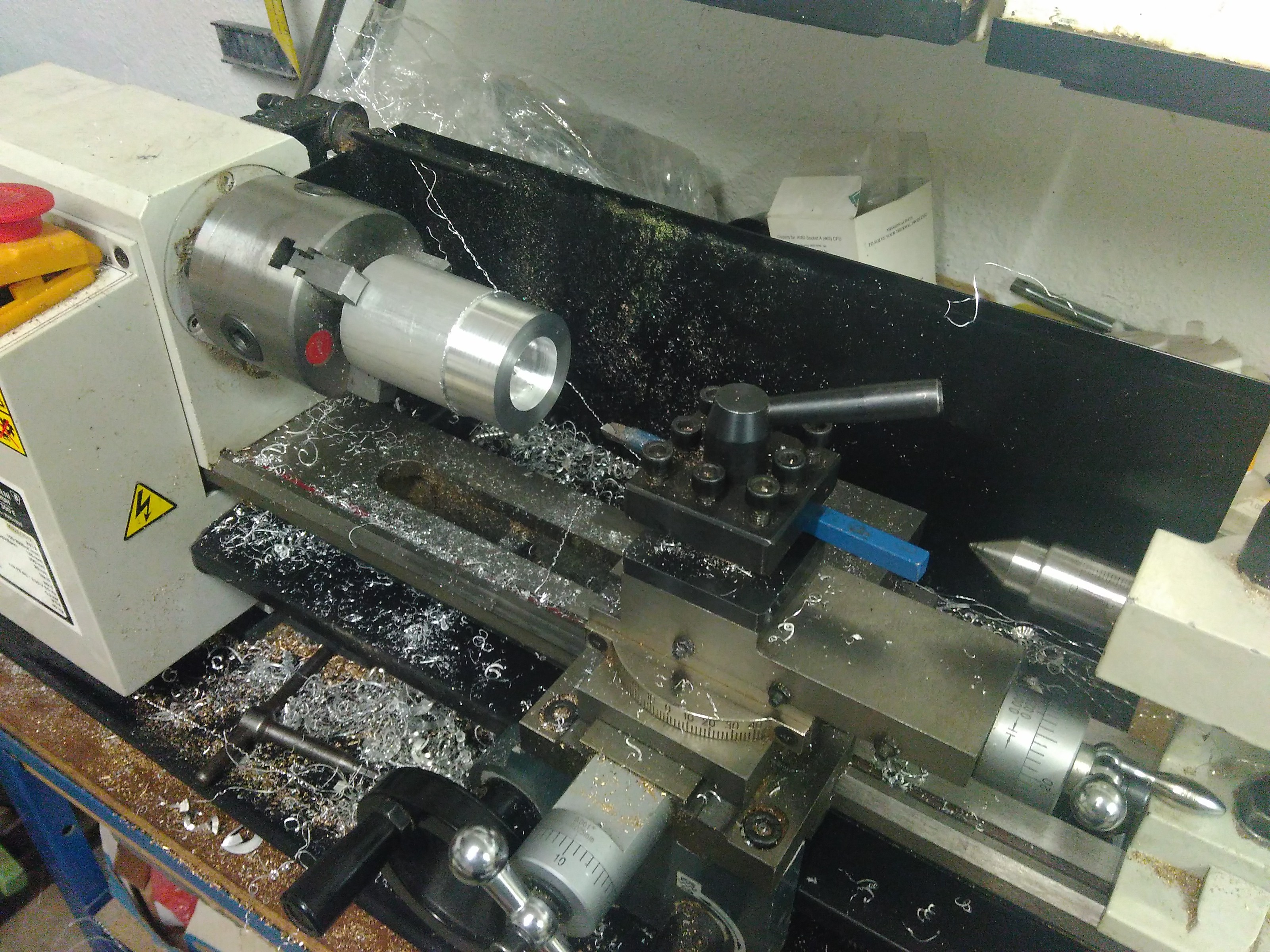
The body is machined from 6082 alluminium alloy.
Battery box is 3D printed from PET-G. To improve the waterproofness I painted it with ABS dissolved in isopropyl alcohol.
Battery
The lamp can run on single 18650, but to improve the burn times, I designed battery box for two cell pack. Two parallel 18650 can provide enough power for the whole day caving trip easily. The battery pack is protected by custom board with BQ29700 controller.


 lion mclionhead
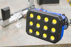
 Tyler Gerritsen
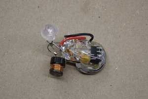
 Elliot Williams
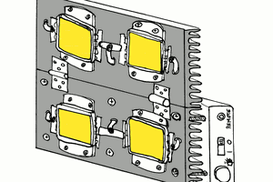
 Yann Guidon / YGDES
Is that your headlamp in the background of this video from Richard Harris (of Thai cave diving rescue fame, among many other cave diving exploits)? https://youtu.be/VjQgxtZ5hEY?si=Mq8ed1HnuaI4uNYi
It looks just like it!