 shlonkin
What this project consists of:
Software(for you):
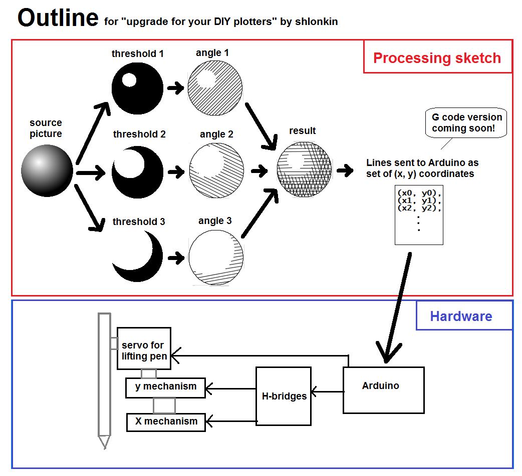
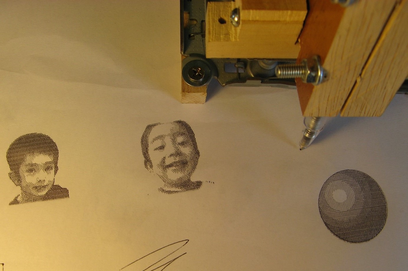
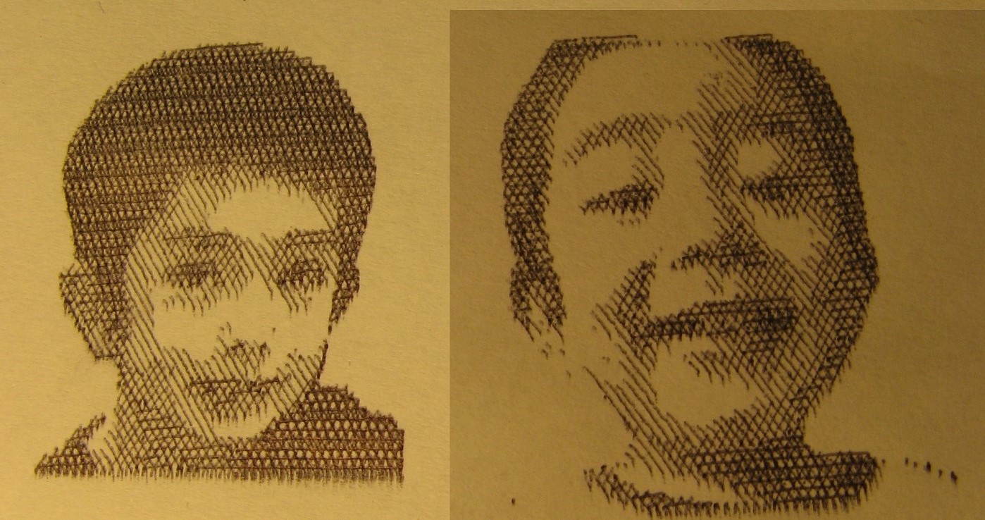
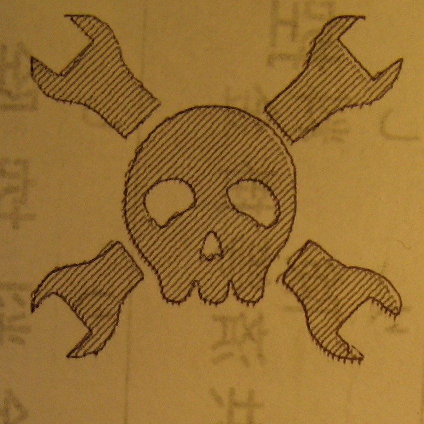
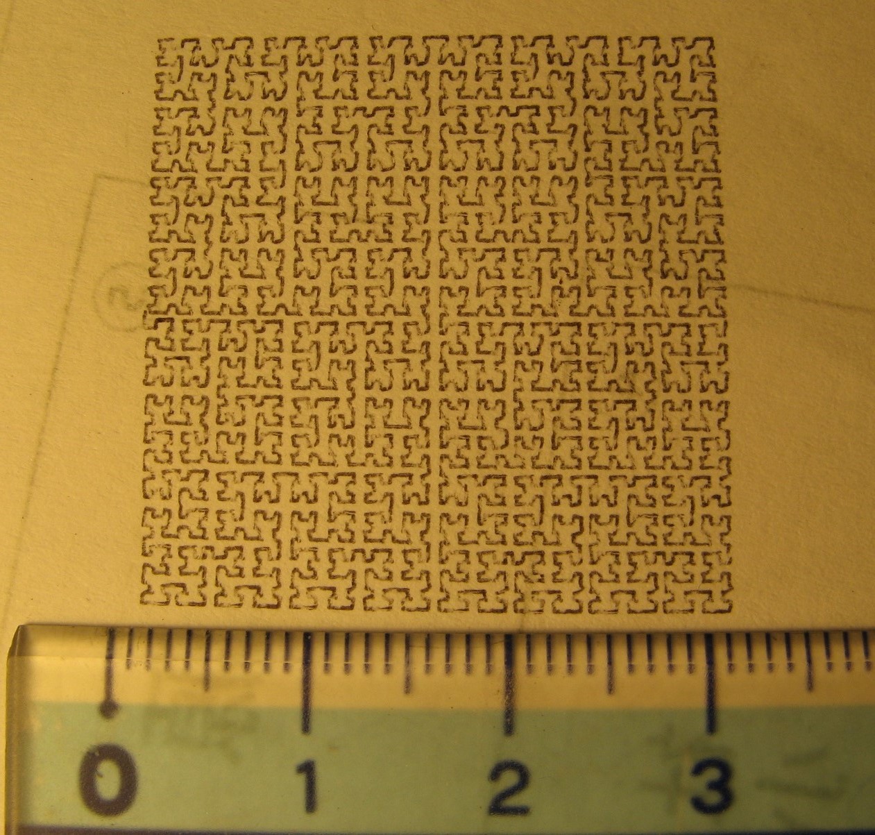
- Takes an image(svg, png, or both at the same time!) and generates a set of cross hatches as well as any paths from the svg file if desired. (see pictures in the gallery to the left)
- Hatch parameters such as number of levels, spacing, angles, thresholds, etc. are all easy to adjust.
- The image is then output as a set of tool paths for your plotter. It speaks directly to your controller via a serial connection.
- Color images can be made using red, blue and yellow hatch directions.
- Flip book style animations can be generated from gif files.
- And more... still coming up with ideas.
Hardware(for me... and you I guess):
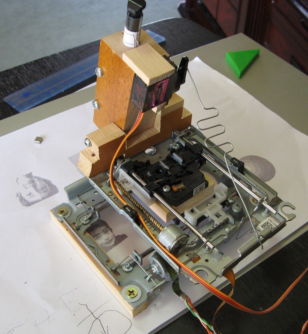
- A mini pen plotter built from DVD drive mechanisms. It's an easy and free way to play around with it.
- Uses Arduino, some H-bridge chips, maybe a servo.
- Might include an automatically feeding paper source(roll of receipt paper) for continuous drawing fun.
- Easily set up to make flip book animations like you've never seen.
Why this project matters: It provides the hacker community with a tool to get more out of their cnc drawing creations. On a greater scale, it may inspire more beginners to jump into the hardware making world by making simple cnc plotter projects much more fun and rewarding. And since everything will be open source with no restrictions, anyone can build upon this and make it their own.


 ssutton4455
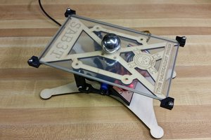
 Tim
Tim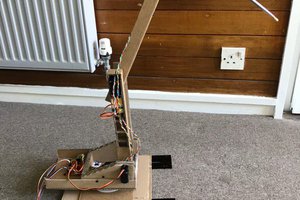
 Benjamin Blundell
Following this, because, if it can also output as several 1-bit bitmaps, it should be ideal for PCBs, too. You have 5 solid colours, no shading, like so:
https://hackaday.io/page/2852-giving-your-pcbs-a-facelift
I also wrote a converter to get bitmaps into Eagle, Altium, or CircuitMaker, so I'd definitely be curious to play around with this. In my five minutes of searching online, I couldn't find any decent pure B&W crosshatching plugins/tools.