It's Hacking Time!
First approach
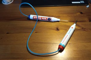
My first thought was to do this the quick and dirty way by soldering an ERM vibration motor in parallel with the tweeter but that proved to be a futile idea since the beep was too short for the motor to spin up.
Working prototype
I decided to use a 555 timer to trigger a bit longer pulse to the motor every time the scanner beeps. The tweeter seemed to receive a couple of volts so without a second thought I threw some components on a breadboard and built a circuit that triggers with a positive pulse. Later on I learned that this was not such a good idea since the tweeter is actually driven by a MOSFET that connects to the ground and in the end I had to find the signal that drives the MOSFET to make the mod work.
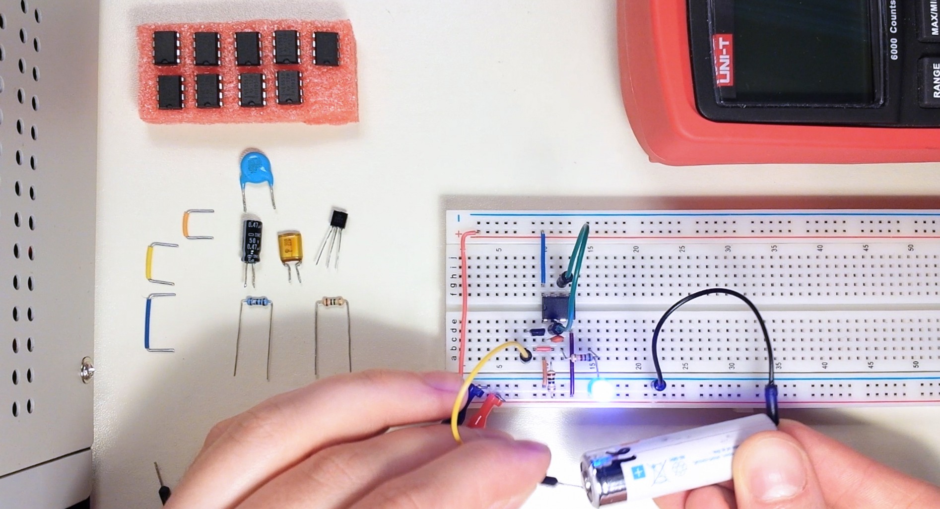
I added a diode across the leads of the motor to prevent back EMF. The 555 datasheet promised a 100 mA maximum current for the output and the motor is rated at 3 V so I added a 10 Ω resistor. With the added resistor I measured the current draw of the motor to be just a bit under 100 mA. It probably draws a lot more at the inrush peak and I definitely should have measured that more carefully but so far the 555 has handled it just fine.
Wrapping things up
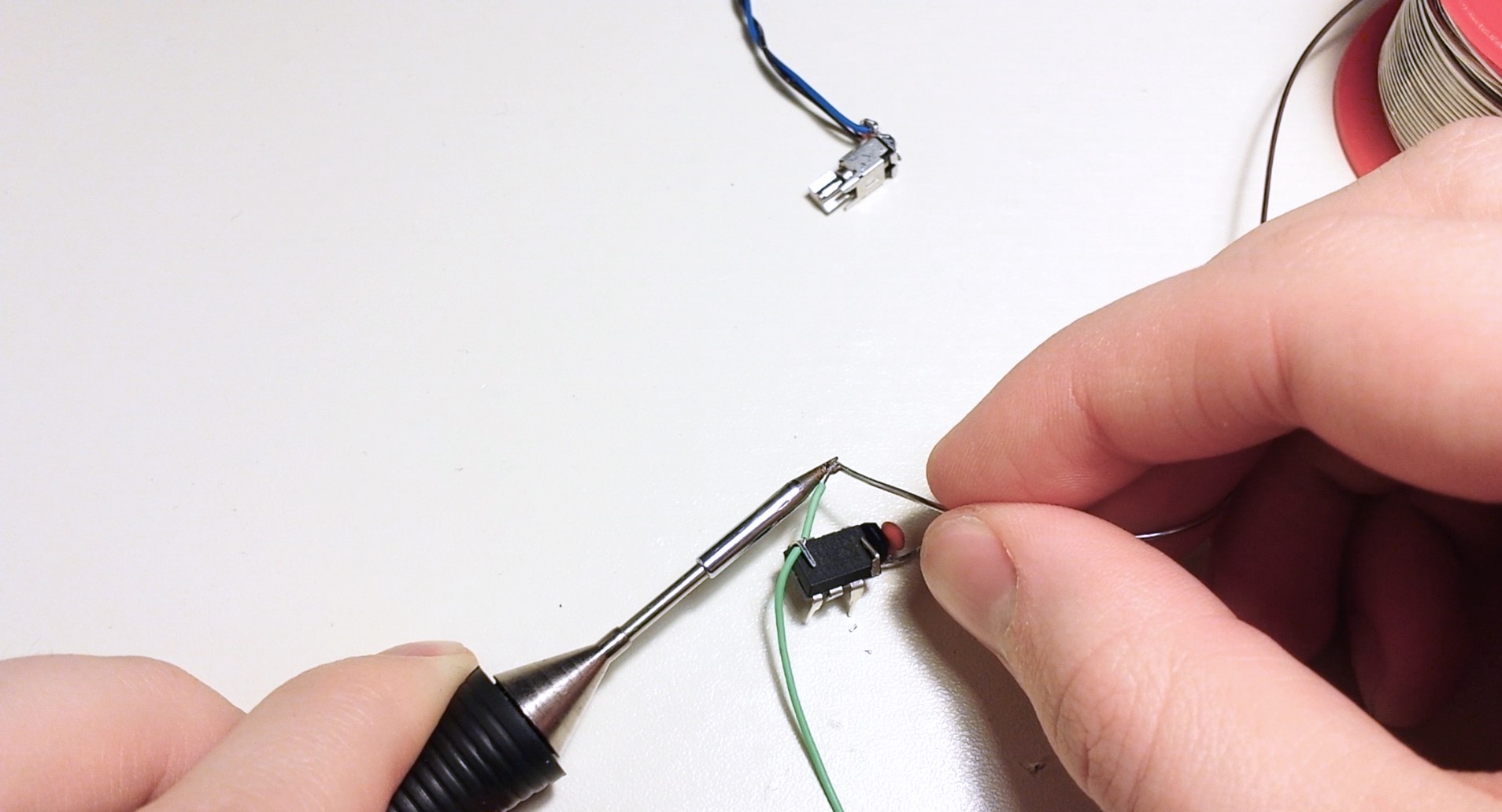
Since the circuit was rather simple I twisted and cut the leads of the components so that they could be soldered as compactly as possible without a PCB to save space. At the time I didn't have any flux and the wire I had salvaged for the project was clearly not meant to be soldered by a mortal so the end result was not a pretty sight. I ended up wrapping the whole thing in hot glue and put some heat shrink tube around it.
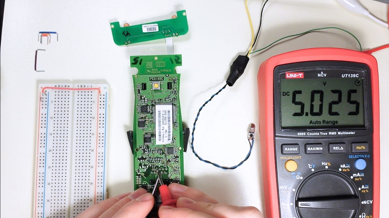
I then probed the scanner circuit to find out where to connect the trigger wire of my circuit and learned that the tweeter was actually driven low side and therefore I could have saved myself a lot of trouble by using the 555 trigger pin directly without a transistor. Eventually I found a pin that apparently controlled the MOSFET of the tweeter and used that positive signal to trigger my circuit.
All that was left to do after that was to solder the wires in place, glue the vibration motor on the lid, screw the scanner back together and test it out.
Some valuable lessons I learned the hard way
- Always check that the salvaged piece of wire you intend to use is solder friendly
- Double check everything before sealing your circuit in hot glue and heat shrink
- Don't assume a component to be driven on the high side without measuring (low side would be a better guess anyway)
- "ERM vibration motor" is a way better search term than "vibrator" if you're trying to find electronic components for haptic feedback
If you are interested in the Club I built this for be sure to check out our FB page

 Matthias Hasenfus
 Steve Schuler