kevinjkrieger
-
Number twoooooooo
08/13/2014 at 06:05 • 0 commentsWho doesn't love Austin Powers? "Come here Number two". Cracks me up every time.
Anywho - It's high time for a project log update I think. I drank a couple pots of coffee this past weekend (long weekend here in Saskatchatooon) and crushed out version two of the PCB to fix a bunch of mistakes and add functionality. I like to think it's prettier as well but who am I to judge my own baby? Even if it is sssshhooooo cuuuuute.
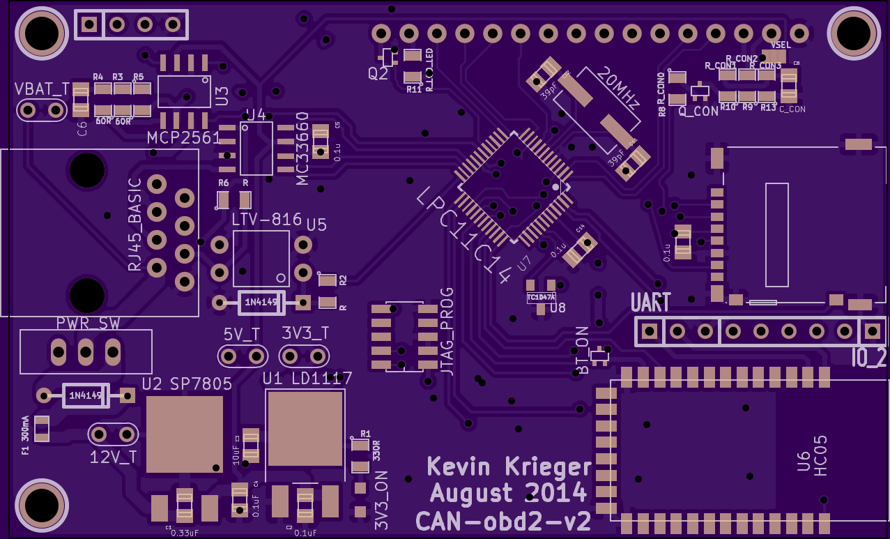
Here's a render from OSHPark:
![CAN obd2 version 2 top render]() Oh baby.
Oh baby. So what's new?
1) I improved some of the silkscreen - generally made the small capacitor values bigger and easier to read, as well as removed things like "K2" which didn't really mean anything to a user of the board. Heck, even I forgot what the connector K2 had on it until I looked at the schematic. Now it's simply called "UART" because that's just the way it is.2) HC05 bluetooth module. You can see this in the bottom right corner and despite being a very small module it still takes up a lot of real-estate. The lack of copper pour (ground plane) underneath the right side of it is so that the antenna can work properly.
3) LCD redesign. I completely did away with the incorrect footprint for the second option LCD. I also improved upon the basic 16 pin LCD by adding a PWM controlled LED backlight circuit and a PWM controlled contrast circuit (mosfet with low pass filter). Now I know you're worried about me and how I've never done this before, but don't you worry - I made it such that I can simply implement the previous resistor divider to control the contrast as before.
4) Input pushbuttons now have a capacitor to ground. It was insane the amount of bounce I was getting with these buttons: FSM4JSMA. As a stop-gap solution I simply disabled interrupts for a second or so after a pushbutton interrupt fired.
5) Fixed the MCP2561 footprint. The error was that my footprint part in my KiCad library had pins going like the following on the left, instead of the correct way on the right:
1 5 1 8
2 6 2 7
3 7 3 6
4 8 4 5
Don't know how that happened.
6) I added a K-line transceiver from Freescale!!!! Woot! It's the MC33660 and it costs $1.06 from Digikey in single quantities. I also added an optoisolator for the L-line, which apparently is only used during initialization and seems to be the dumb sibling to the K-line. Oh well.
7) Instead of the large through hole LM335, I opted for the small, cute, TC1047A as a board temperature sensor. Bonus: It doesn't require a pull up resistor. (Yes I know the lm335 comes in surface mount but I don't have any).
8) All through hole resistors are now surface mount!
9) Naturally, I rid myself of the solder jumpers for the K-line, L-LIne and SCS line. I determined that the SCS line is pretty useless for me through some gogoogaling, so I choose to ignore.
10) Total reboot of the net connections to be able to fit everything on the same size board. I really wanted to keep the board size the same. Both for costs and also because it is a standard board size from the "Sick of Beige" standard. I had to remove one of the screws, but who really cares? This process involved me trying to lay out the two sided board for a couple hours before realizing I needed to flip the whole LPC11C14 180 degrees and start from scratch. So that's what I did and boy it worked! I had both monitors going, one displaying the actual physical PCB layout and one displaying the schematic diagram, which I tweaked incrementally while moving parts around the PCB and discovering how to route traces that don't intersect each other. Yay for general purpose IO pins.
Here's a render of the bottom:
![]()
-
The CAN bus speaketh
07/25/2014 at 05:52 • 1 commentThere's a wonderfully simple app for android called BlueTerm. I'm using it to pipe all the data from my LPC11C14 through the HC-05 bluetooth module onto my phone, where I have the ability to just store all of it. Damn that's just too easy now isn't it? I'm going to start using these HC-05 devices everywhere.
So far I haven't been able to get my car to respond to any queries on the CAN bus, but I can listen to everything it is saying at the least. Here's a quote:
message 2, ID: 294: 0 c 40 1 36 87 0 1f
message 2, ID: 294: 2 c 40 1 36 87 0 2c
message 2, ID: 294: 2 c 40 1 36 87 0 3b
message 2, ID: 1dc: 2 0 0 2a 0 0 0 7
message 2, ID: 1dc: 2 0 0 c 0 0 0 0
message 2, ID: 1dc: 2 0 0 2a 0 0 0 f
message 2, ID: 1dc: 2 0 0 c 0 0 0 0
message 2, ID: 136: 0 2 0 0 0 0 0 c
message 2, ID: 39: 0 c0 0 0 0 f ff ff
message 2, ID: 294: 2 c 40 1 36 87 0 2c
message 2, ID: 1dc: 2 0 0 c 0 0 0 0
message 2, ID: 13a: 51 0 31 0 0 0 0 88
message 2, ID: 37c: 0 0 0 15 c 0 0 0
message 2, ID: 1dc: 2 0 0 2a 0 0 0 f
message 2, ID: 158: 0 0 0 0 0 0 0 a
message 2, ID: 405: 0 0 4 0 0 0 2 36
message 2, ID: 294: 2 c 40 1 36 87 0 1d
message 2, ID: 320: 0 0 21 ff ff ff ff ff
message 2, ID: 164: 0 0 80 0 43 0 0 2c
message 2, ID: 164: 0 0 80 0 43 0 0 2c
message 2, ID: 164: 0 0 80 0 43 0 0 2c
message 2, ID: 17c: 0 0 0 0 11 0 20 5b
message 2, ID: 39: 0 fd ff ff ff ff ff ff
message 2, ID: 164: 0 0 80 0 43 0 0 3b
message 2, ID: 164: 0 0 80 0 43 0 0 3b
Well hot-diddly-damn, I don't know what any of that means. I've got plenty of MegaBytes of this stuff sitting in BlueTerm logs on my phone and computer though. What's next?
-
So blue
07/25/2014 at 05:45 • 0 commentsI think I understand why my RPM values didn't mean anything... I had accidentally set up my received filter on the LPC11C14 to receive EVERYTHING. oops.
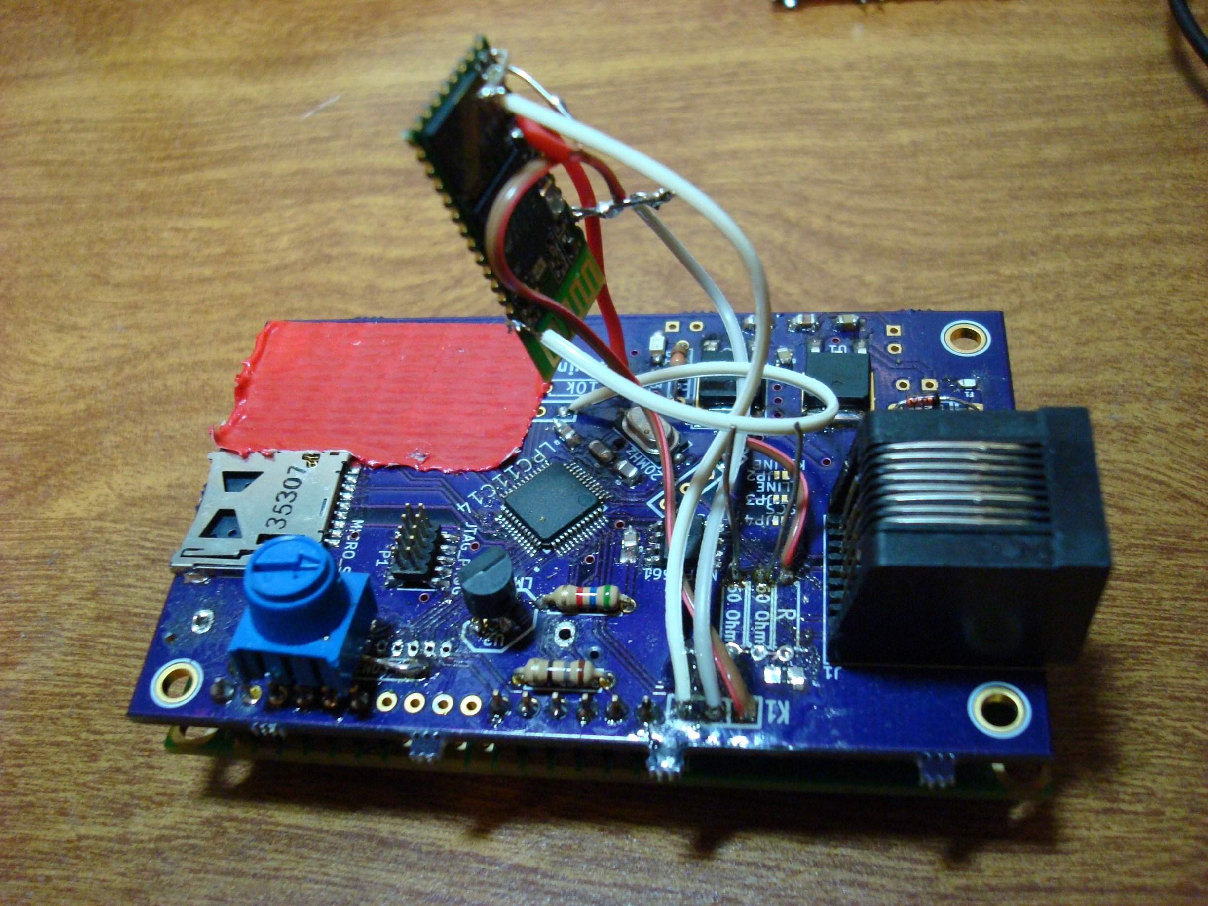
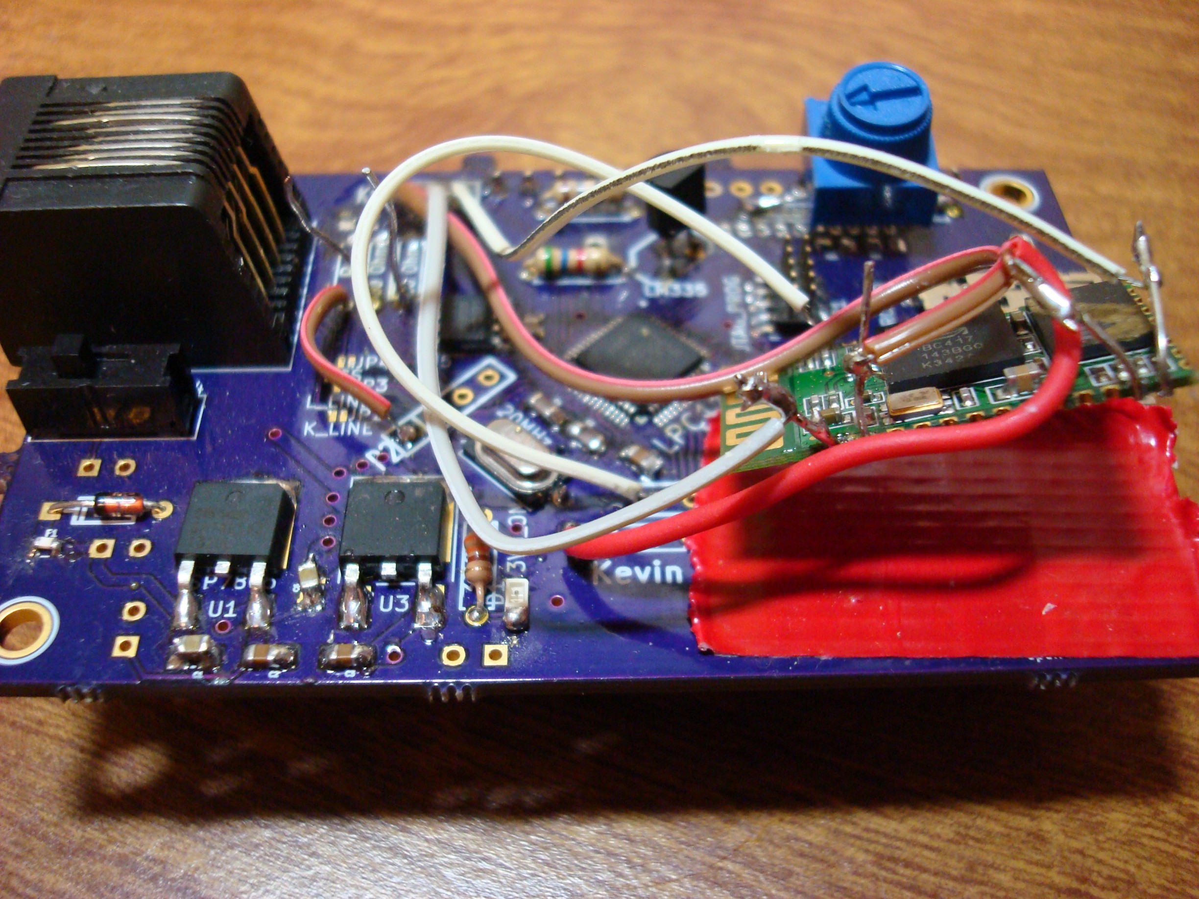
In order to aid in debugging - I had an idea - why not get a serial stream of data going? I can use an HC-05 bluetooth module to connect my phone to the CAN-obd2 board :).
![]()
Check it - You can see that I bodged it in there really well. I'll rest it on that piece of red Duck-tape (yes Duck tape brand - deal with it).
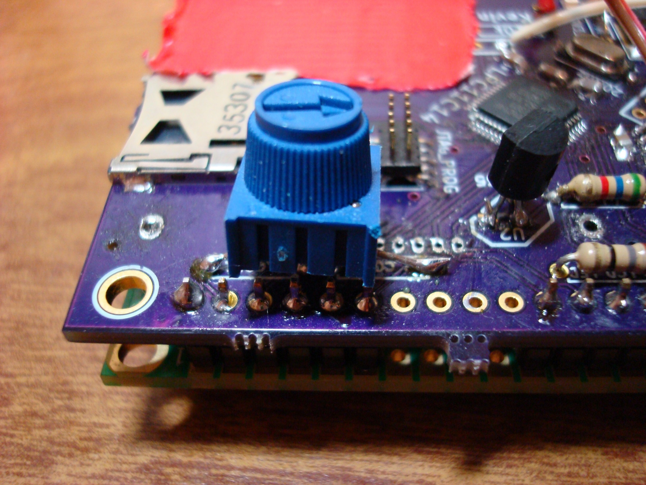
Oh yeah, I forgot to mention that I put an el-cheapo pot on the contrast adjust of the LCD:
![]()
Here's another closeup of the bluetooth connections:
![]() I added code to the boot-up function of the LPC11C14 to tell the HC-05 in AT mode to speak at 115200 baud. 9600 is too damn slow.
I added code to the boot-up function of the LPC11C14 to tell the HC-05 in AT mode to speak at 115200 baud. 9600 is too damn slow. -
Meaningless numbers
07/25/2014 at 05:38 • 0 commentsAfter fixing the little fiasco with the cable that shorted power and ground, fixing the CAN transceiver wiring to account for the mixed up footprint, and having a coffee - I was ready to go again. Lets check it out shall we?
After much fighting with CAN baud rates (It turns out my Civic runs at 500kHz) I was finally able to see data on my 2008 Honda Civic's CAN bus! It... it works!
*happy dance*
Okay - focus. The first test I wanted to do was to read out the RPM of my vehicle using the OBD2 standard PID query. Explained here: http://en.wikipedia.org/wiki/OBD-II_PIDs#Mode_01
This involves my device setting up a CAN message object to read anything coming from ID 0x7E8 through 0x7EF. Then my device sets up a CAN message object to transmit to ID 0x7DF (the OBD2 broadcast ID) and for the 8 data bytes, uses 0x02, 0x01, 0x0C, 0x55, 0x55, 0x55, 0x55, 0x55. This means please tell me the engine RPM pretty please. At which point the car should ACK my packet and respond with a few things: from ID 0x7E8 through 0x7EF (not sure which one) I should get 8 bytes: 0x04, 0x41, 0x0C, 0xA, 0xB, 0xXX, 0xXX, 0xXX. Which means 4 meaningful data bytes in the stream, freeze frame data, PID 0x0c (rpm) and the two RPM bytes A and B. See http://en.wikipedia.org/wiki/OBD-II_PIDs#Query.
However, the value I'm getting (displayed on LCD screen) seems meaningless...
More later. Need sleep.
-
Mistake #3 - Enabling Disabling ... arglkh.asd;lfkj
07/25/2014 at 05:07 • 0 commentsYep mistake #3 already. Didn't think I could get off so easy. So I think we can all agree the goal of this whole project necessitates that the CAN transceiver works properly. I refer you to Mistake #1, let me quote: "always triple check your footprints." I guess I would need time travel to have listened to my own advise here.
Upon checking out the CAN transceiver to make sure it was outputting something when I was using the CAN module... I notice a little problem. I swapped one side of the footprint! Heh.
STDBY pin 8 was actually SPLIT pin5CAN High pin 7 was actually CAN Low pin 6
CAN Low pin 6 was actually CAN High pin 7
SPLIT pin 5 was actually STDBY pin 8.
Oooops. What does this mean? Well - the two CAN pins are no problem, that just means I have to swap the wires in the cable that I made. How about the STDBY and SPLIT pins? currently I'm not using the SPLIT pin - since I don't have the R2, R3, R4 or C11 components in the following image populated I can just cut the trace connected to CAN_XCVR_RS and then bodge a wire from one of the spare GPIO to the one end of R2. It's fixable! On a side note: I would populate the three resistors and capacitor if my device was going to be one end of the CAN bus, but it is not, there are already two termination ends to the CAN bus in the Honda Civic's circuitry. Read the datasheet for the MCP2561 for details.
![]()
Oh BTW, the RS pin enables or disables the transceiver, so it's kinda important. That's all for now.
-
Mistake #2 - My heart skipped
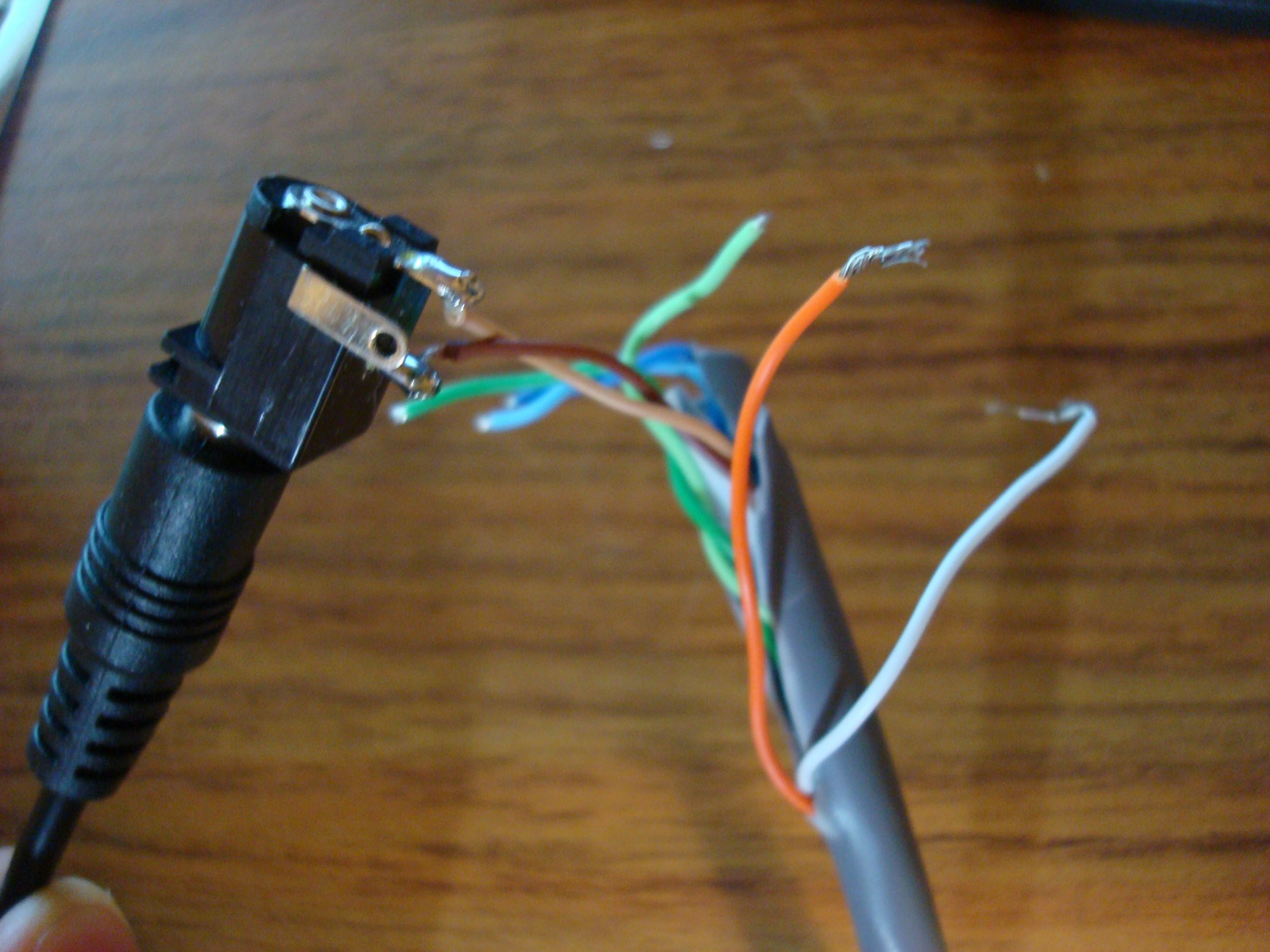
07/25/2014 at 04:50 • 0 commentsHere we go, things are getting serious in this relationship. It's time to make a cable that will carry the very electrons I control between my car and my CAN-obd2 board. It's like the calm before the storm.
.
.
Here, we need a little comic relief: http://www.banggood.com/Car-OBD2-16Pin-Male-To-Female-Extension-Cable-Diagnostic-Adapter-p-80098.html?currency=CAD&utm_source=google&utm_medium=shopping&utm_content=ruby&utm_campaign=Auto-ca&gclid=CKu41dfS378CFQ0baQodhHoA6Q
I bought my OBD2 cable to cut in half from banggood.com . Oh, engrish you never fail us. Their slogan is "Shopping with Fun, Best Bang For Your Buck". Indeed :).
After cutting the thing in half, probing with the DMM to make sure I had the right cables, and soldering it all up it was time to head to the garage to violate my car's diagnostic port.
Plug it in. Turn key, slide the switch and 'POP!'. No dash lights, no centre console power, no power to close my open sunroof. Shit.
Let me tell you - I had the fear in me at this point, what exactly did I explode inside my modern automobile?
I grabbed the DMM and settled in to the fuse box on the interior of the vehicle. All good.
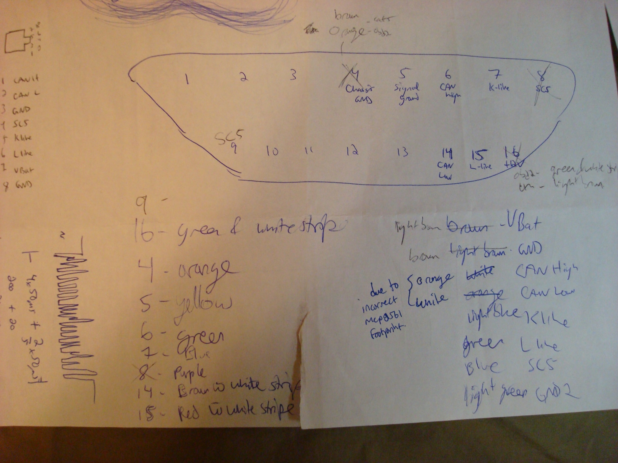
I pop the hood and check the engine compartment ones. OH THANK GOD - it's just a 10 AMP fuse and I had another on hand. I replace the fuse and make sure my car works properly still - I had to dig out the anti-theft code for the CD player but nothing is permanently damaged. Back to the drawing sheet.
![]() My page that shows just how stupid/colourblind I was. Light brown (GND) and brown (Unswitched lead-acid battery) look the same in my basement dungeon I guess. This is the cause of the short and subsequent frying of 10A worth of automotive fuse.
My page that shows just how stupid/colourblind I was. Light brown (GND) and brown (Unswitched lead-acid battery) look the same in my basement dungeon I guess. This is the cause of the short and subsequent frying of 10A worth of automotive fuse. I think I need to drop the heartrate down below 140bpm before coming back.
-
LCD Says Hi
07/25/2014 at 04:24 • 0 commentsShazam!
LCD done. I ported a PIC LCD library (a few routines for interfacing to 4 bit mode HD44780) to the LPC11C14. See the original here: http://blog.vinu.co.in/2011/06/4-bit-interfacing-of-16x2-lcd-display.html Thanks bud!
The ADC tested out well, the SD card is being written to, the UART works (hooked it up to my Bus Pirate, arrrrrr) the only thing left to do is make a cable between the car and the board and test it out. I am excite.
-
Mistake #1
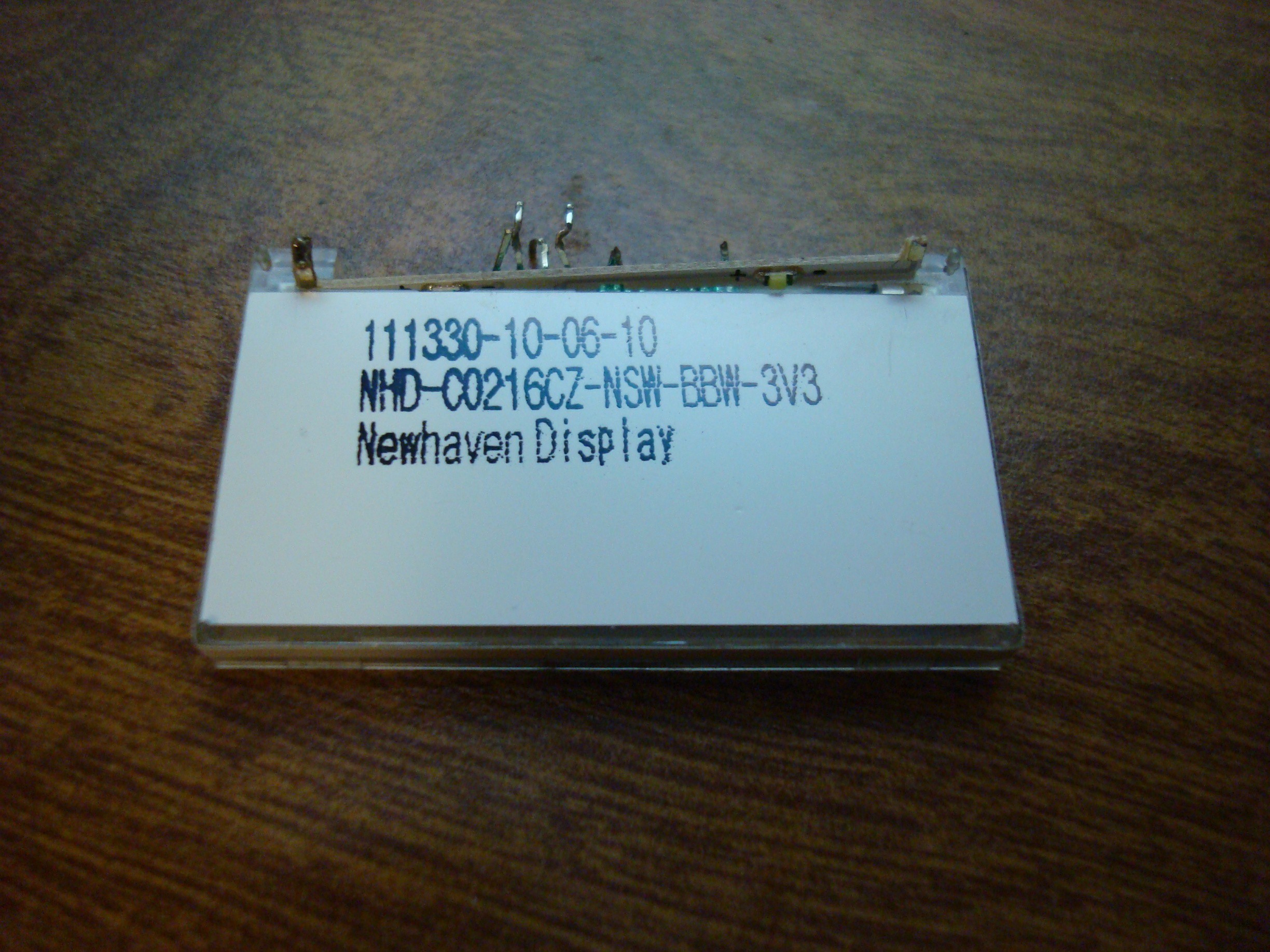
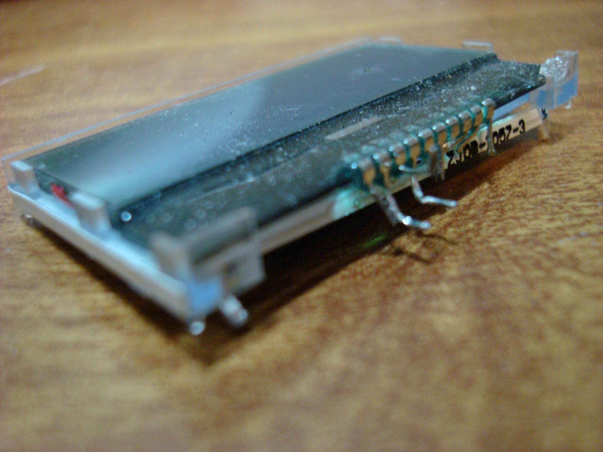
07/25/2014 at 04:04 • 0 commentsAh, poop. The COG LCD I soldered to the board was lighting up whenever I applied power - so I assumed it was working and that a little code-fu would let me make the magical characters appear on it... no such luck. I tried and tried, I hooked up the Saleae Logic analyzer to it and verified I was putting out the correct stuff... but still nothing.
A bit of investigation caused me to do this:
![]()
![]()
![]()
I found that I had correctly made the footprint for the backlight... but the rest of the pins were backwards. That got me frustrated, so I tried to remove it but the result was just a mess and I gave up and started cutting it off.
After cooling down I soldered the circuitry for a regular HD44780 style LCD to the board. Then the LCD itself. It tested fine after powerup. There you have it - always triple check your footprints.
-
First Program
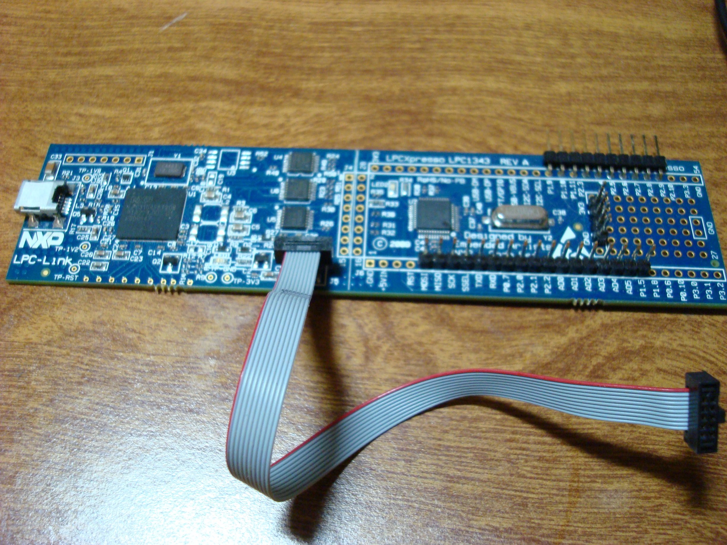
07/25/2014 at 03:20 • 0 commentsWell that was a bit of a hassle. I followed the instructions here though: http://www.lpcware.com/content/project/lpcopen-platform-nxp-lpc-microcontrollers/lpcopen-v200-quickstart-guides/lpcopen-1
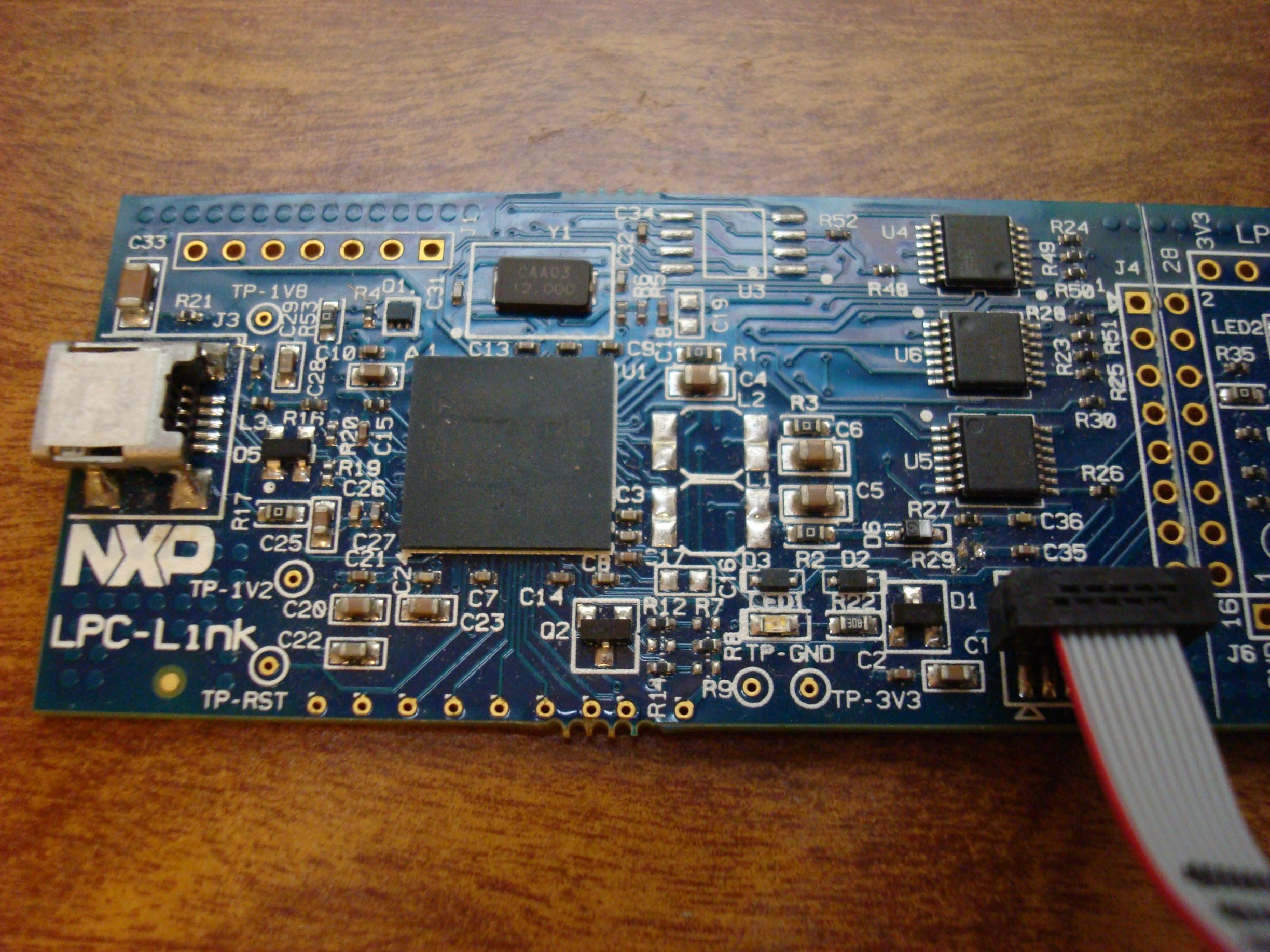
Also, in order to power the board via the LPC-Link, you need to have the resistor R29 populated (solder jumper it!). It supplies 3.3V, so the temperature sensor won't work, and neither will the CAN transceiver or +5V LCDs, but at least you can program the thing. Check It: http://www.embeddedartists.com/sites/default/files/docs/schematics/LPCXpressoLPC1343revA.pdf on page 4/5 you'll see the text "J5 can connect to external JTAG interface if LPCXpresso targe side (LPC1343) is disconnected." So you just cut the traces like in the photo here:
![]()
And you can populate the jumper that you see unpopulated here:
![]() (R29 is just to the left upper corner of the connector).
(R29 is just to the left upper corner of the connector).It worked! I just modified the example blinky project to output a square wave on one of my broken out headers. I did find out that a couple of the pins on that header are open-drain... That always gets me.
-
Powerup
07/25/2014 at 02:18 • 0 commentsWell well well. What is the first thing you do after you have first populated your circuit board? Test the power supplies!
I hacked together a barrel jack connector and an ethernet cable, found out which wires were connected to +12V and GND on my board, and soldered it up. I just used a +9V wall wart.
![]()
All the power supplies test good, the LED lights up, and nothing overheats. That's all for today.
CAN-obd2
This project was started as a way to display and save information from my 2008 Honda Civic's OBD2 port.
 Oh baby.
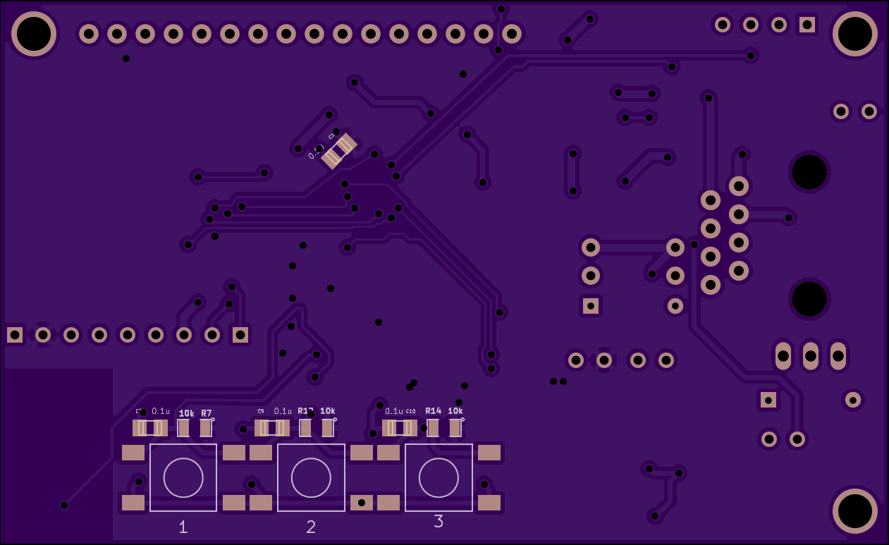
 I added code to the boot-up function of the LPC11C14 to tell the HC-05 in AT mode to speak at 115200 baud. 9600 is too damn slow.
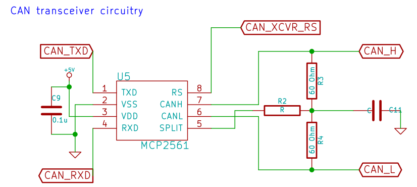
 My page that shows just how stupid/colourblind I was. Light brown (GND) and brown (Unswitched lead-acid battery) look the same in my basement dungeon I guess. This is the cause of the short and subsequent frying of 10A worth of automotive fuse.
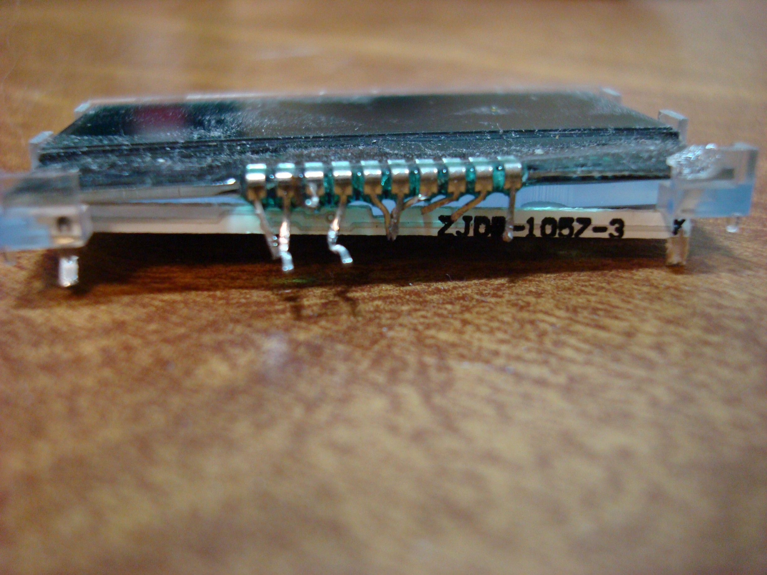
 (R29 is just to the left upper corner of the connector).