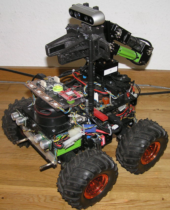
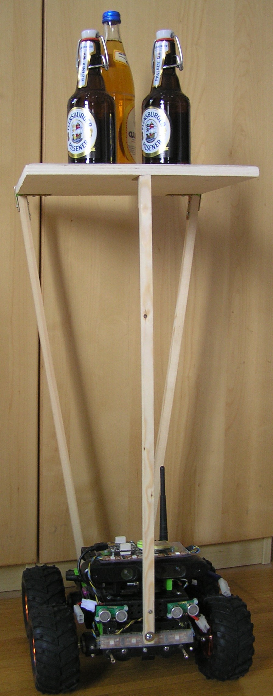
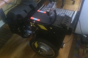
Mechanic:
- Wild Thumper 4wd chassis
- Motors upgraded with encoders
- Total weight: 3.3kg
Power supply:
- Battery: 2x 7.2V NiMh, fused with 30A (slow)
- 5V via voltage regulator D24V50F5 (5A), fused with 3A (fast)
The two batteries are connected in parallel using a LM5050-2 active ORing circuit each. Another LM5050-2 can be connected in parallel for docking station supply.
Computer:
- Solid Run Hummingboard (i.MX6 ARM Cortex-A9 Dual Core 1GHz, 2GB RAM)
- AVR Atmega32 for motor control
- AVR Atmega328 (Arduino Nano) for I/O
Peripheral:
- Hummingboard: GPS (uart), IMU (USB), 3D-Camera (USB), 2xAVR over I2C, PCA9517 "Level translating I2C-bus repeater" to bridge the 3.3V with the 5V I2C.
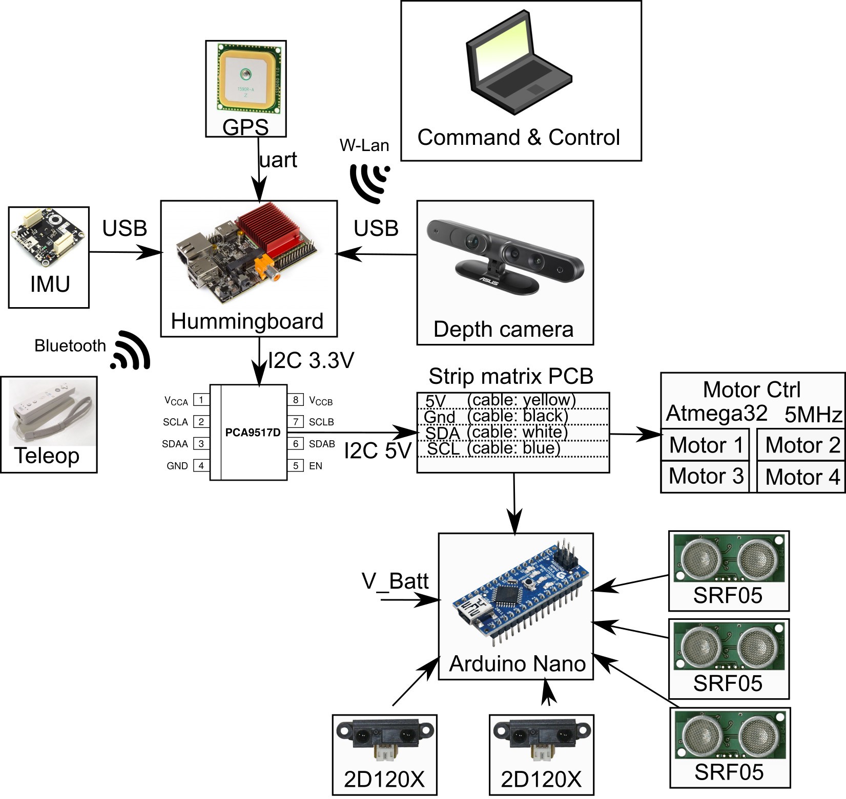
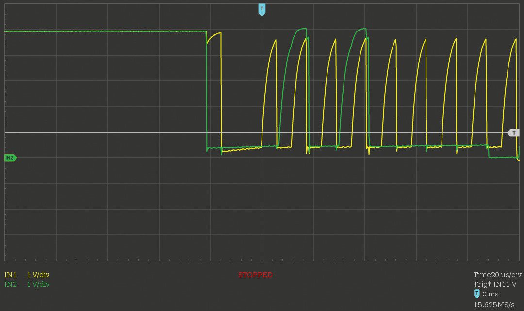
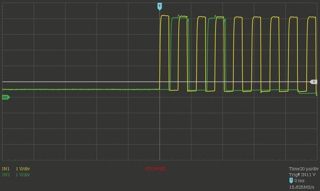
Motor control:
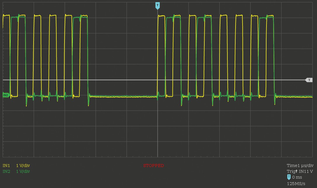
- Motors driven by 4x VNH2SP30, one for each on a 20kHz PWM
- Speed control (PID) and Odometry from wheel encoders are calculated on Atmega328 (yes, doing float on it).
Inputs/Outputs on Atmega328:
- 3x distance sonar sensors, 2x infrared distance sensors, battery voltage
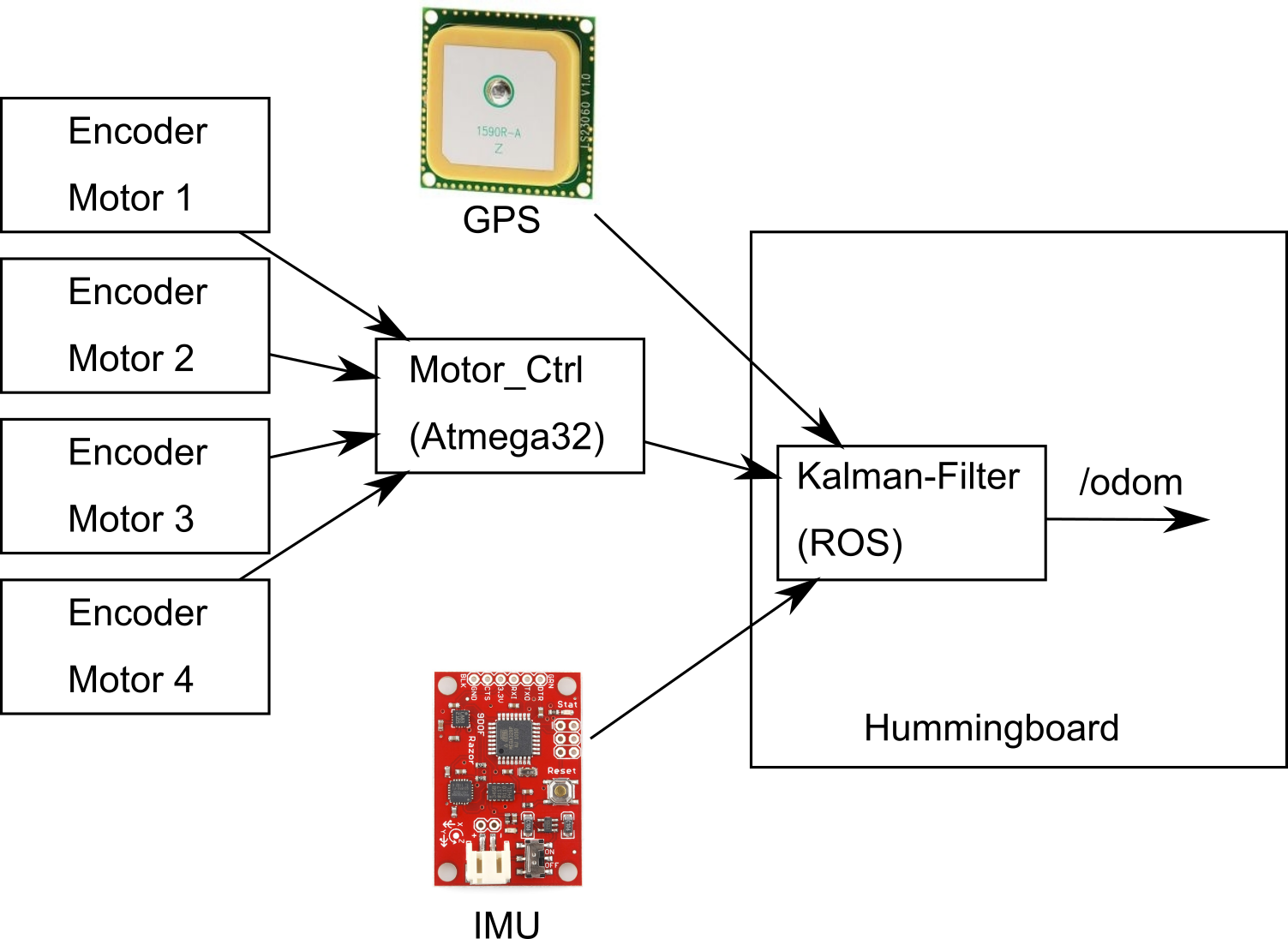
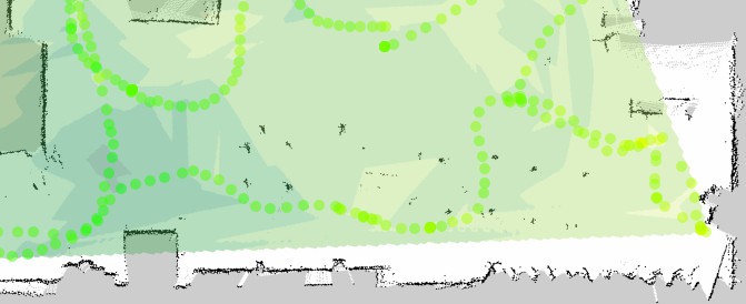
Odometry calculation:
- Odometry from wheels corrected with Tinkerforge IMU Brick 2.0 with Kalman filtering
![]()
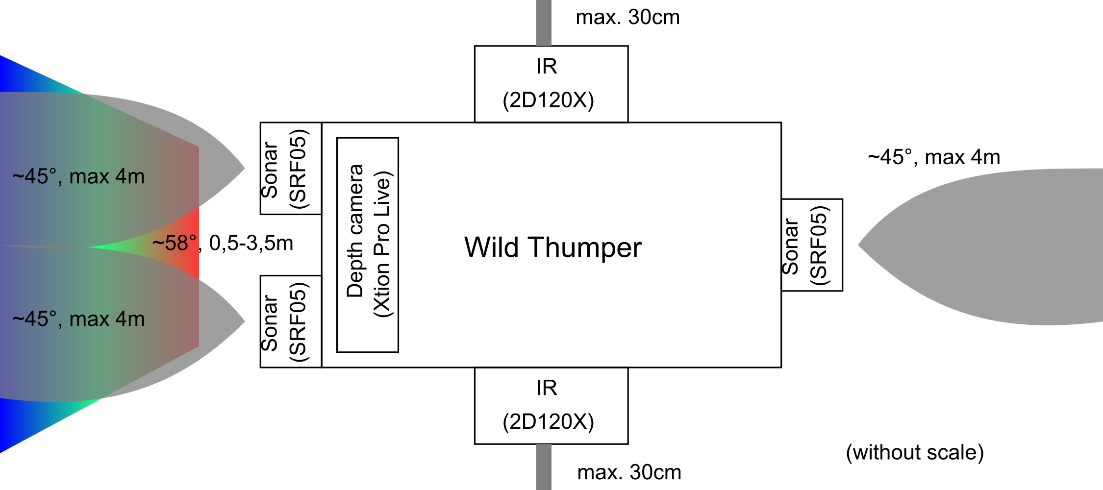
Sensors:
- Xtion Pro Live depth camera
- 2x IR 2D120X (1x left, 1x right)
- 3x sonar SRF05 (2x front, 1x aft).
The point of the sonar sensors is to correct the dead zone of the depth camera in less then 0.5m
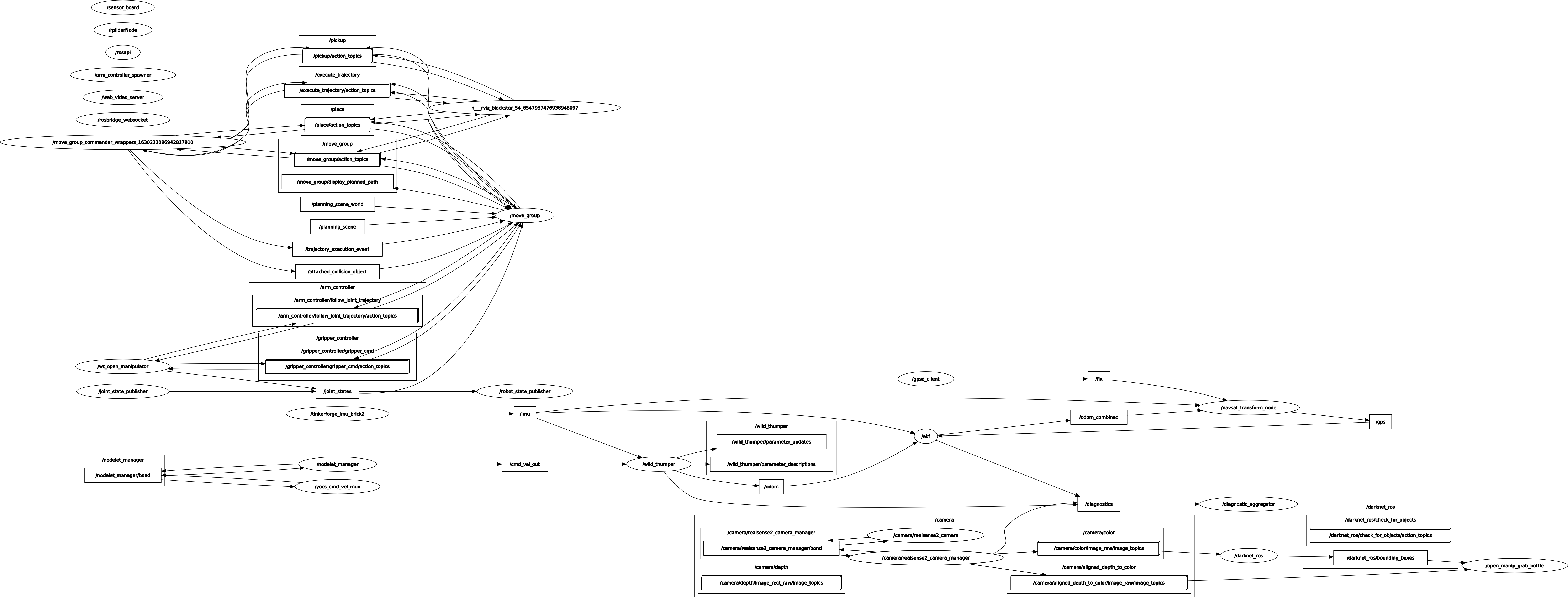
Software:
- Debian Stretch
- Robot Operating System (ROS) Kinetic
Object following:
With ultra-wideband (UWB) modules the robot can follow a target, in the following video a R/C car:
Details in the corresponding log "Follow me - part 4".
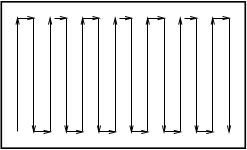
GPS test video:
The following videos shows the robot automatically driving a square by four GPS waypoints. The front camera is shown on the lower left, the rviz map video is shown on the upper left.
LED stripe demo:


 J Groff
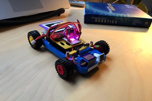
 Piotr Sokólski
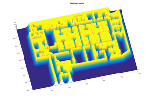

 Rodolfo
An interesting project that I will have a much close look at and modify it. Perhaps using a Raspberry Pi 4 + arduino IO . Have you thought of using Lidar ??
But Lidar modules can be rather expensive. Keep up the excellent work!