 Sophi Kravitz
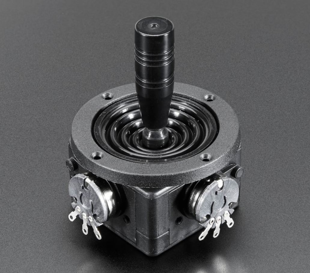
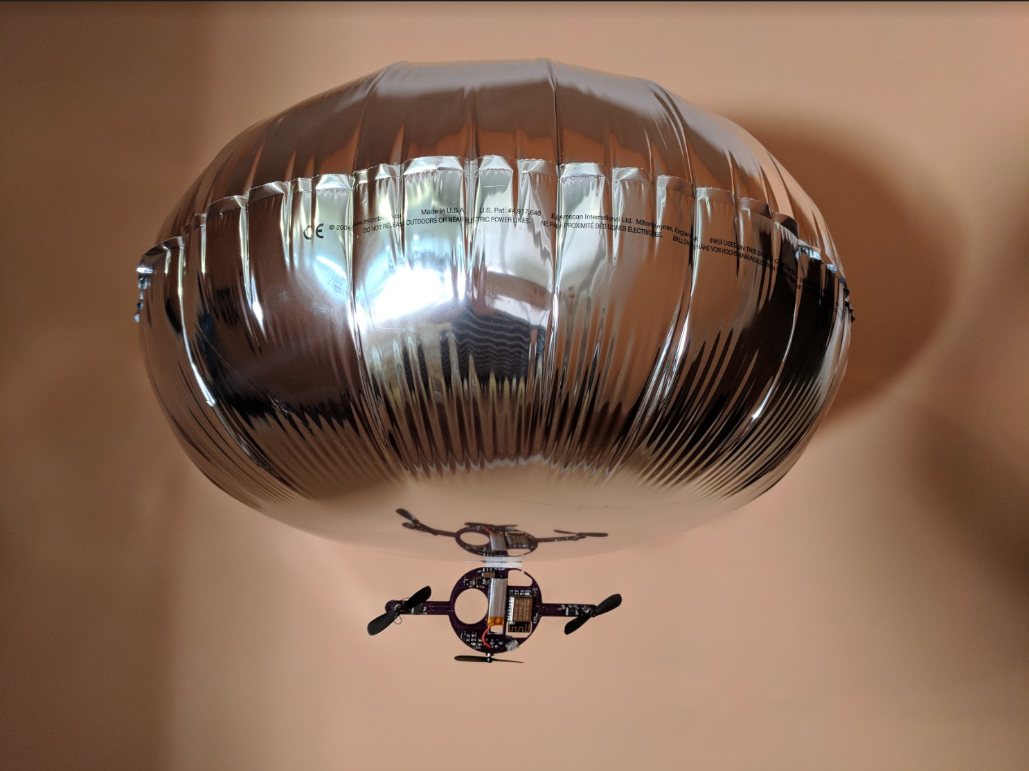
This is a remote control blimp which is controlled by joystick.
Thanks to @oshpark for supporting this project.
One of the things I'll use this for is a blimp obstacle course.
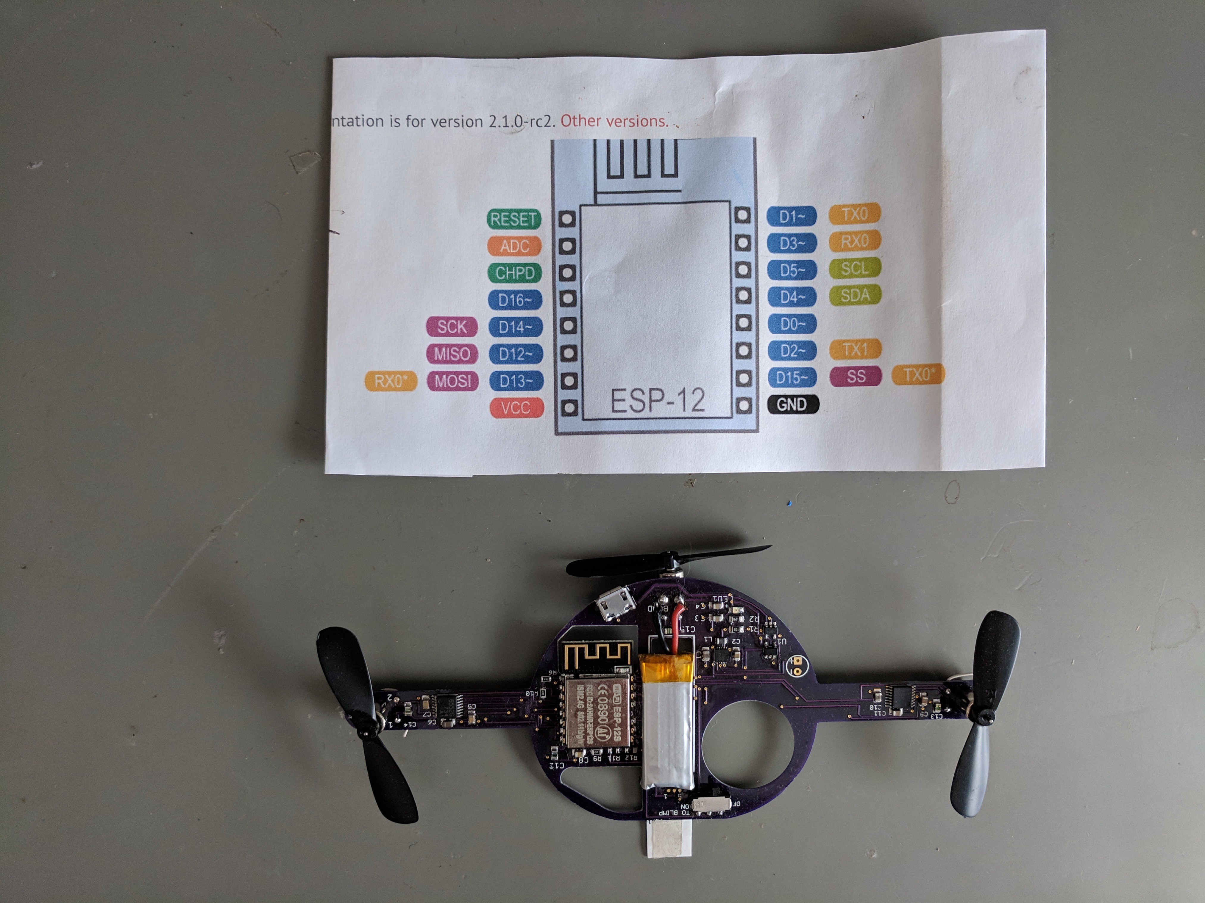
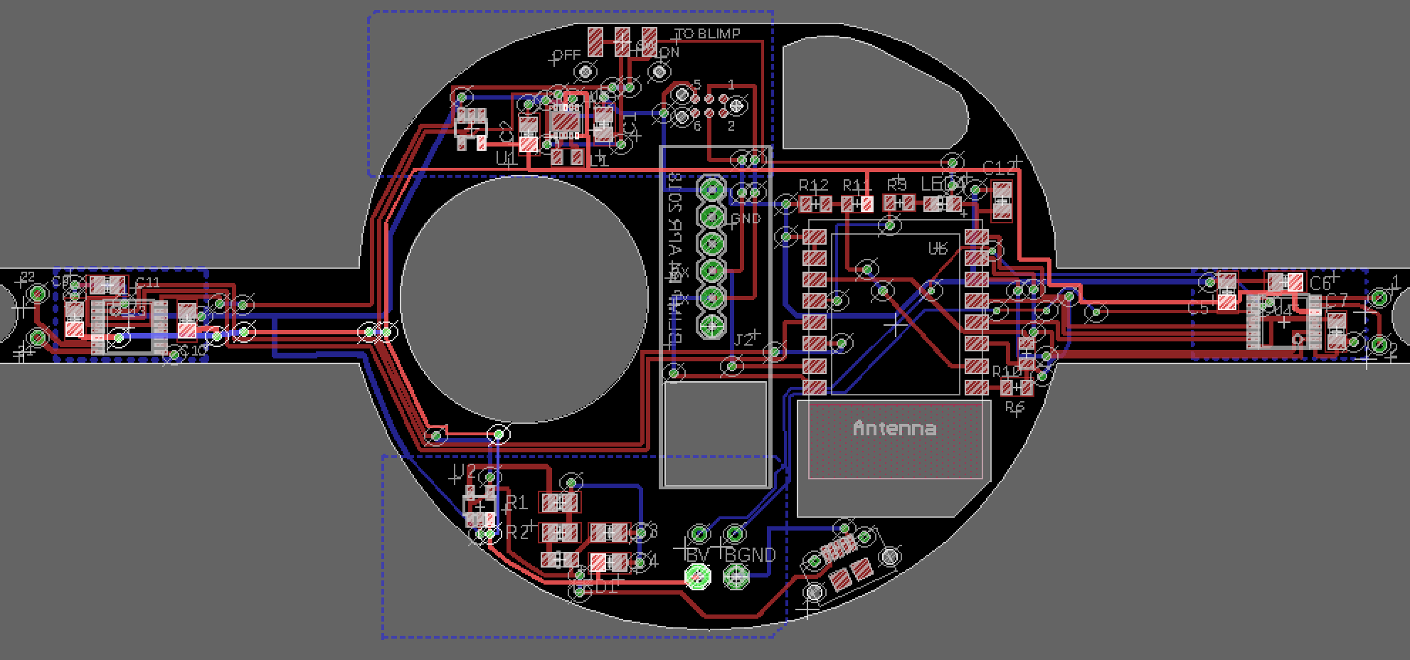
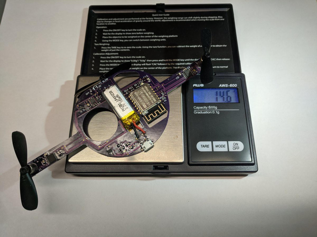
BlimpLi controller PCB measures approximately 110mm x 35mm and has 4 circuit modules.
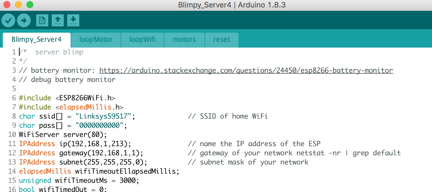
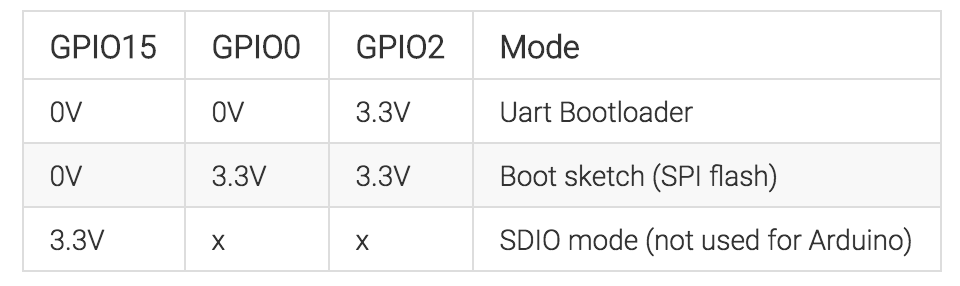
- Wireless communications using WiFi/ ESP8266
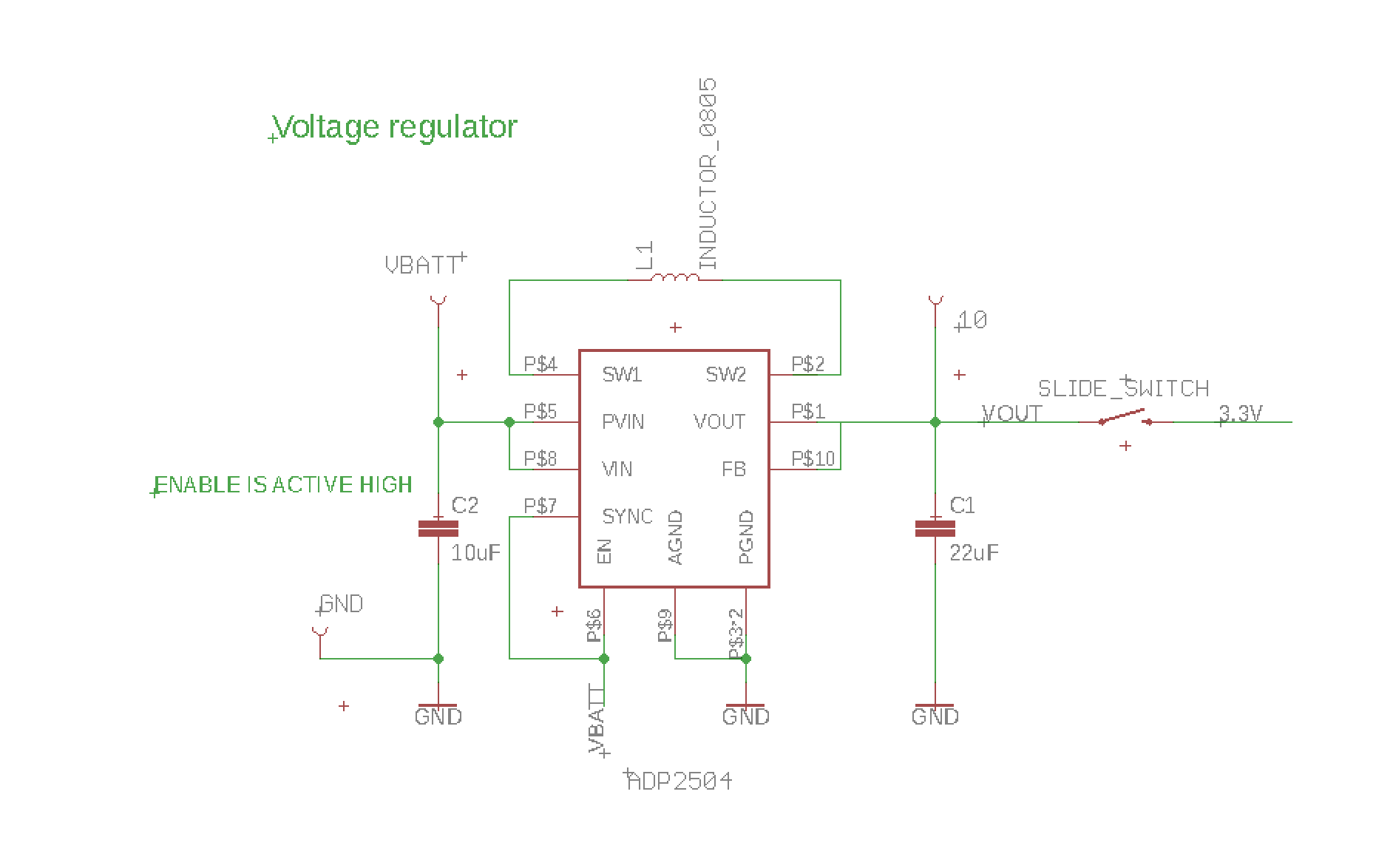
- Voltage regulator: VBatt (4.2V -3.7V) to 3.3V
- Motor driver circuit for 3 motors 3.3V, 20mA
- Battery charging circuit for 1-cell Li-Ion Polymer battery


 mauswerkz
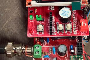
 Jon Kunkee
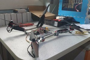
 RobotDigg ME
 Daren Schwenke
Maybe interesting for you:
https://blog.hackster.io/introducing-the-blimpduino-2-d551f4270084
Looks like it flies a bit more stable than your blimp :-)