 Ted Yapo
In #TritiLED, I've been experimenting with ways of making LED glow markers that run for years on a single lithium coin cell. Recently, Elliot Williams started playing with the idea on his #ATtiny45 EverLED project. This got me thinking - first, I should post some progress on TritiLED - but also about other uses.
The idea here is to see how little power is required to drive 7-segment displays to usable visibility in the dark. As a possible use case, imagine a night-table clock you only need to read in the dark (if it's too bright to read the display, you should be out of bed and hacking). Or, maybe a UTC clock for astronomy.
Another possibility I'd like to explore is driving an LCD backlight with an efficient circuit and LED - that would probably be the overall best solution, but you know, more LEDs = more cool.
I happened to have a couple of Kingbright SC10-21SRWA common-cathode displays left over from the #The Diode Clock, so I decided to start with one of these. This display is a 660nm "ultra-red" display with 120 mcd output typical at 10mA - that's a lot of photons, and these displays can look extremely bright when driven at "normal" currents. (Does anyone else remember when this red color was the only really bright LEDs available?). The disadvantage to this wavelength is that it's not very efficient at stimulating the human retina, in fact for scotopic (dark-adapted) vision, it's only 0.03% as efficient as 507nm cyan light! A second disadvantage to this display is that each segment is made of two-series connected LEDs, requiring a higher drive voltage.
I used this display because I had it. I've looked for high-efficiency 7-segment displays in cyan color near the 507nm visual peak, and they don't appear to exist. I might try making some of my own with discrete LEDs.
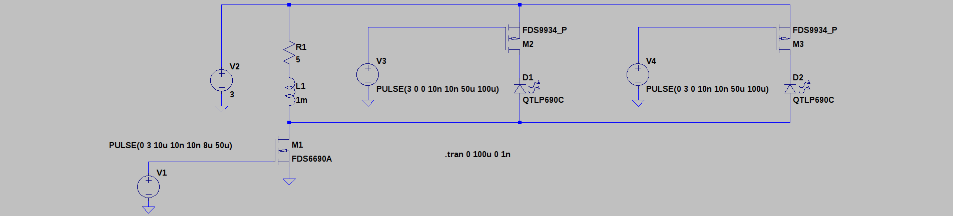
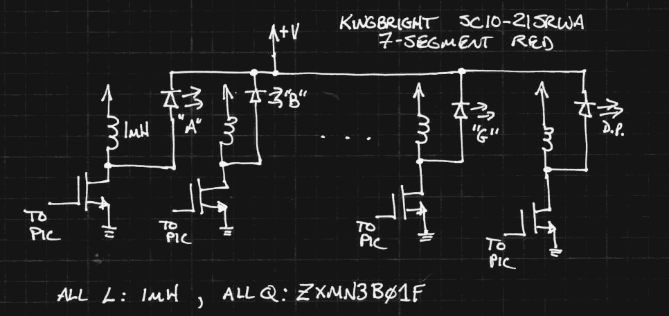
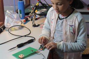
So far, I've assembled a prototype but haven't written any software to test it. I'll post the schematic after I get some initial results (in other words, after I draw it :-). You can see in the image that I've used (8) 1mH inductors and SOT-23 MOSFETs to drive the segments (and decimal point) in the same way TritiLED works. The MOSFETs are mounted on #Ugly SMD Adapters I ordered from OSH Park. I've chosen a PIC16F1718 as a test processor because I had some handy - it's not the 16LF version, which would be even lower power, but I suspect the PIC power consumption will be dwarfed by that required for the display.
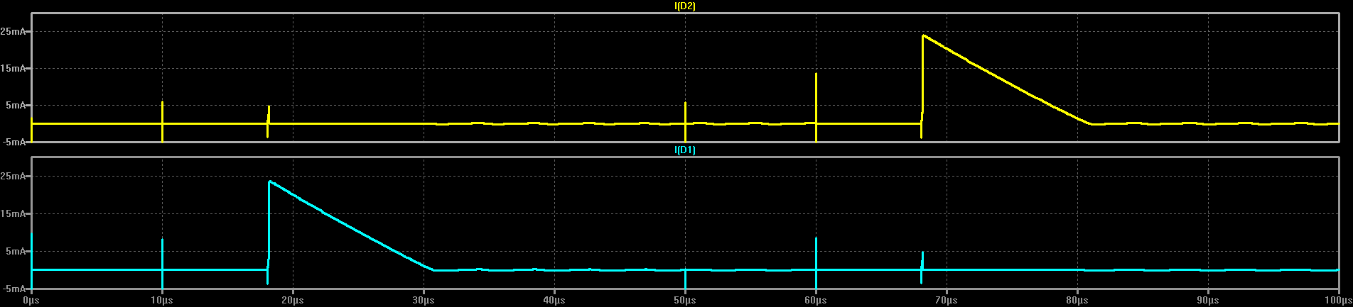
That's all for now, except for one teaser: some initial experiments showed one of the segments was easily visible when driven with a TritiLED circuit consuming about 20 uA. For all 7 seven segments plus the DP, that would mean abut 160uA total, which would run for 2 months on a CR2032 or about 2.5 years on a pair of lithium (LiFeS2) AA's. But maybe we can do better?


 Christoph Tack
 Yann Guidon / YGDES
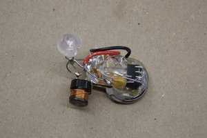
 Elliot Williams
On another note - while the LED displays do not have required wavelength, some older ones are hackable, provided you have your favorite wavelength LED in 0603 or 0402 package:
http://www.ledstyles.de/index.php/Thread/24566-Tuning-alter-Ziffernanzeigen-mit-neuen-LED-Chips/
https://www.mikrocontroller.net/topic/284082
It's all in German, I don't understand much of it, but the pictures are international.