Close
0%
0%

Simple Concurrent Tones for the Arduino

The Arduino tone library does not support concurrent multiple tones.
Now I am sure someone has done this before but here is my take.

Similar projects worth following
The goal is to play more than one track (i.e. tone) of a midi file at a time on an Arduino.

Concurrent Tones on the Arduino

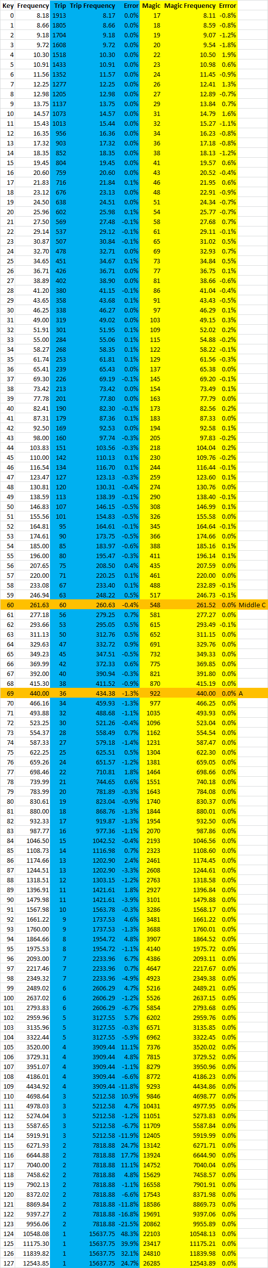
The goal of the project is to play more than one tone at a time on an Arduino.

No doubt this has been done before but here is my take.

The "Green Light Go" webpage (http://greenlightgo.org/projects/midi-to-arduino/) has a Midi to Arduino Sketch converter. It's a really good place to start, upload your midi and download your Arduino Sketch, and play. It uses the Arduino tone library so it can only play one channel at a time. Even so it does a pretty good job.

I did not initially understand why the channels would "drop out" until I realised the tone library was not concurrent.

This project looks at a concurrent tones generation. The core interrupt service routine is from my modem project.

If setting hardware registers and interrupts service routines frighten you then perhaps this is not a project for you.

---

Okay, its done. The Files area contains an executable the converts MIDI files into Arduino sketches. Let me know if you have any problems.

There are two examples to try.

AlanX

Popcornx.mp3

This is what it sound like.

MPEG Video - 1.29 MB - 09/28/2017 at 05:17

Download

Midi2Arduino_exe

Well you know what to do!

- 22.50 kB - 09/28/2017 at 05:10

Download

SimpleMidiPlayerPopcorn.ino

Hook up three 100R speakers to A0, A1 and A2, and your set to go!

ino - 88.32 kB - 09/28/2017 at 09:48

Download

SimpleMidiPlayerYaketyAxe.ino

Hook up three 100R speakers to A0, A1 and A2, and your set to go!

ino - 33.68 kB - 09/28/2017 at 09:48

Download

popcorn-GXSCC_version.mid

A pretty reasonable test file and sound good too!

audio/mid - 20.49 kB - 09/28/2017 at 05:10

Download

View all 6 files

  • Final Log

    agp.cooper09/28/2017 at 05:09 0 comments

    Final Log

    The processing code work just fine off the Arduino. Go figure?

    I have written a tool that takes a MIDI file and converts it to an Arduino sketch:

    • Midi2Ardunio.exe

    I have not 100% tested everything so if something is not working lot me know and I will fix it. I have put it in my Files area along with a MIDI (Popcorn) and the Arduino sketch:

    • SimpleMidiPlayer.ino

    I have put a sample MIDI (popcorn), a recording of the Arduino playing it.

    ---

    Spoke to soon. The very next file I tested crashed!

    Took all afternoon until I realised that I MUST open binary files with "rd" and not "r", otherwise 0x0A is interpreted as a "CR" and the next char is dropped.

    Okay, amended executable uploaded.

    ---

    Regards AlanX

  • A Working MIDI Player

    agp.cooper09/27/2017 at 02:33 0 comments

    A Working MIDI Player

    Not quite, I had to hack Track 5 (noise) to get it to work properly, something is upsetting Channel 0?

    So hook up two 100R speaker to A1 and A2 (Channel 1 and 2) and listen to Popcorn.

    Source? http://www.mediafire.com/file/pocsc984peahdod/popcorn-GXSCC_version.mid

    Hint: I uploaded the full Arduino sketch to Files.

    Here is the code (with most of the MIDI removed):

    /*
       A Concurrent Tone Sketch
       Six channels: A0-A5
       Procedure is SetKey(Pin,Key);
       Setq Key to 0 to turn off sound
       Middle C is Key 60   
       Author: agp.cooper@gmail.com
    */
    #define MaxChannels 6  // A0-5
    #define TickDuration 1 // 1 ms 
    #include <avr/pgmspace.h>
    /* popcorn-GXSCC_version.mid */
    const byte PROGMEM MidiData[] = {
    0x4D, 0x54, 0x68, 0x64, 0x00, 0x00, 0x00, 0x06, 0x00, 0x01, 0x00, 0x05,
    ...
    0x40, 0x8D, 0x0F, 0xFF, 0x2F, 0x00,
    };
    const unsigned long MidiData_length = 0x00004752;
    const unsigned int Key2Magic[128] = {
        0,     18,    19,    20,    22,    23,    24,    26,
       27,     29,    31,    32,    34,    36,    38,    41,
       43,     46,    48,    51,    54,    58,    61,    65,
       69,     73,    77,    81,    86,    91,    97,   103,
       109,   115,   122,   129,   137,   145,   154,   163,
       173,   183,   194,   205,   218,   230,   244,   259,
       274,   290,   308,   326,   345,   366,   388,   411,
       435,   461,   488,   517,   548,   581,   615,   652,
       691,   732,   775,   821,   870,   922,   977,  1035,
      1096,  1162,  1231,  1304,  1381,  1464,  1551,  1643,
      1740,  1844,  1954,  2070,  2193,  2323,  2461,  2608,
      2763,  2927,  3101,  3286,  3481,  3688,  3907,  4140,
      4386,  4647,  4923,  5216,  5526,  5854,  6202,  6571,
      6962,  7376,  7815,  8279,  8772,  9293,  9846, 10431,
     11051, 11709, 12405, 13142, 13924, 14752, 15629, 16558,
     17543, 18586, 19691, 20862, 22103, 23417, 24810, 26285
    };
    // Define various ADC prescaler
    const byte PS_16=(1<<ADPS2);
    const byte PS_32=(1<<ADPS2)|(1<<ADPS0);
    const byte PS_64=(1<<ADPS2)|(1<<ADPS1);
    const byte PS_128=(1<<ADPS2)|(1<<ADPS1)|(1<<ADPS0);
    /* ISR: Tone on A0-5 */
    volatile unsigned int magic=0;
    volatile unsigned int magic0=0;
    volatile unsigned int magic1=0;
    volatile unsigned int magic2=0;
    volatile unsigned int magic3=0;
    volatile unsigned int magic4=0;
    volatile unsigned int magic5=0;
    volatile unsigned int phase=0;
    volatile unsigned int phase0=0;
    volatile unsigned int phase1=0;
    volatile unsigned int phase2=0;
    volatile unsigned int phase3=0;
    volatile unsigned int phase4=0;
    volatile unsigned int phase5=0;
    volatile unsigned long master=0;
    ISR(TIMER2_OVF_vect)
    {
      if (phase<0x8000) {
        phase+=magic;
        if (phase>=0x8000) master++;
      } else {
        phase+=magic;
      }
      phase0+=magic0;
      phase1+=magic1;
      phase2+=magic2;
      phase3+=magic3;
      phase4+=magic4;
      phase5+=magic5;
      if (phase0<0x8000) PORTC&=B11111110; else PORTC|=B00000001;
      if (phase1<0x8000) PORTC&=B11111101; else PORTC|=B00000010;
      if (phase2<0x8000) PORTC&=B11111011; else PORTC|=B00000100;
      if (phase3<0x8000) PORTC&=B11110111; else PORTC|=B00001000;
      if (phase4<0x8000) PORTC&=B11101111; else PORTC|=B00010000;
      if (phase5<0x8000) PORTC&=B11011111; else PORTC|=B00100000;
    }
    void SetKey(unsigned int Channel,unsigned int Key)
    {
      if (Channel==0) magic0=Key2Magic[Key];
      if (Channel==1) magic1=Key2Magic[Key];
      if (Channel==2) magic2=Key2Magic[Key];
      if (Channel==3) magic3=Key2Magic[Key];
      if (Channel==4) magic4=Key2Magic[Key];
      if (Channel==5) magic5=Key2Magic[Key];
      // Turn it off
      if (Key==0) {
        if (Channel==0) phase0=0;
        if (Channel==1) phase1=0;
        if (Channel==2) phase2=0;
        if (Channel==3) phase3=0;
        if (Channel==4) phase4=0;
        if (Channel==5) phase5=0;
      }
    }
    void PlayMIDI(void)
    {
      // Header Variables
      unsigned int format=0;
      unsigned int nTrks=0;
      unsigned int trk;
      unsigned int division=0;
      bool BadHeader=false;
      bool BadTrack=false;
      // Temporary data variables
      unsigned char Data0;
      unsigned char Data1;
      unsigned char Data2;
      unsigned char Data3;
      // Decoding varaibles
      bool MoreData;
      unsigned char Data;
      unsigned int Key;
      unsigned long DeltaTime;
      unsigned long TrackPtr[128];
      unsigned long TrackLen[128];
      unsigned long TrackEnd[128];
      unsigned long TrackTime[128];
      unsigned char MIDIMsg[128];
      unsigned char Channel[128];
      bool TrackWait[128];
      /* Read MIDI...
    Read more »

  • Using a Counter for the ISR

    agp.cooper09/25/2017 at 15:27 0 comments

    Using a counter for the ISR

    I received a suggestion to use a counter and trip method for the Interrupt Service Routine (ISR). While is was not keen as the method (Direct Digital Synthesis) is pretty standard and gives the best long term accuracy. But that is not the whole story as this accuracy comes at the cost of sub-harmonics on the higher frequencies. Anyway I decided to have a look at it. First the speadsheet calculations:

    As you can see the DDS (magic) method is more accurate especially at high frequencies and around the frequencies of most interest (middle C and A), than the count and trip method. The greatest fault of the count and trip is it cannot play some keys above 1.1 kHz.

    The ISR is running at 31275.5kHz which leaves 31 us for ISR code execution time. Not a lot! You can go faster which would push these problems into higher frequencies but really for most music that is going to be played on an Arduino, it does not matter.

    The second test was to listen to the tones. In this case the Count and Trip method has a much cleaner sound. At high frequencies the sub-harmonics of the DDS method are quite obvious. Again, does not matter for most of the music that is going to be played on an Arduino.

    Here is the code for the Count and Trip version:

    /*
       A Concurrent Key/Tone Sketch
       Six channels: A0-A5
       Procedure is SetKey(Pin,Key);
       Setq Key to 0 to turn off sound
       Middle C is Key 60   
       Author: agp.cooper@gmail.com
    */
    #define TickDuration 1 // 1 ms 
    const unsigned int Key2Trip[128] = {
     1913, 1805, 1704, 1608, 1518, 1433, 1352, 1277, 
     1205, 1137, 1073, 1013,  956,  903,  852,  804, 
      759,  716,  676,  638,  602,  569,  537,  507, 
      478,  451,  426,  402,  380,  358,  338,  319, 
      301,  284,  268,  253,  239,  226,  213,  201, 
      190,  179,  169,  160,  151,  142,  134,  127, 
      120,  113,  107,  101,   95,   90,   85,   80, 
       75,   71,   67,   63,   60,   56,   53,   50, 
       47,   45,   42,   40,   38,   36,   34,   32, 
       30,   28,   27,   25,   24,   22,   21,   20, 
       19,   18,   17,   16,   15,   14,   13,   13, 
       12,   11,   11,   10,    9,    9,    8,    8, 
        7,    7,    7,    6,    6,    6,    5,    5, 
        5,    4,    4,    4,    4,    4,    3,    3, 
        3,    3,    3,    2,    2,    2,    2,    2, 
        2,    2,    2,    2,    1,    1,    1,    1 
    };
    // Define various ADC prescaler
    const byte PS_16=(1<<ADPS2);
    const byte PS_32=(1<<ADPS2)|(1<<ADPS0);
    const byte PS_64=(1<<ADPS2)|(1<<ADPS1);
    const byte PS_128=(1<<ADPS2)|(1<<ADPS1)|(1<<ADPS0);
    /* ISR: Tone on A0-5 */
    volatile unsigned int count=0;
    volatile unsigned int count0=0;
    volatile unsigned int count1=0;
    volatile unsigned int count2=0;
    volatile unsigned int count3=0;
    volatile unsigned int count4=0;
    volatile unsigned int count5=0;
    volatile unsigned int trip=31;
    volatile unsigned int trip0=0;
    volatile unsigned int trip1=0;
    volatile unsigned int trip2=0;
    volatile unsigned int trip3=0;
    volatile unsigned int trip4=0;
    volatile unsigned int trip5=0;
    volatile unsigned long master=0;
    ISR(TIMER2_OVF_vect)
    {
      count++;
      count0++;
      count1++;
      count2++;
      count3++;
      count4++;
      count5++;
      if (count>=trip) {
        master++;
        count=0;
      }
      if (count0>=trip0) {
        if (trip0>0) PINC|=B00000001;
        count0=0;
      }
      if (count1>=trip1) {
        if (trip1>0) PINC|=B00000010;
        count1=0;
      }
      if (count2>=trip2) {
        if (trip2>0) PINC|=B00000100;
        count2=0;
      }
      if (count3>=trip3) {
        if (trip3>0) PINC|=B00001000;
        count3=0;
      }
      if (count4>=trip4) {
        if (trip4>0) PINC|=B00010000;
        count4=0;
      }
      if (count5>=trip5) {
        if (trip5>0) PINC|=B00100000;
        count5=0;
      }
    }
    void SetKey(unsigned int Channel,unsigned int Key)
    {
      if (Channel==0) trip0=Key2Trip[Key];
      if (Channel==1) trip1=Key2Trip[Key];
      if (Channel==2) trip2=Key2Trip[Key];
      if (Channel==3) trip3=Key2Trip[Key];
      if (Channel==4) trip4=Key2Trip[Key];
      if (Channel==5) trip5=Key2Trip[Key];
      // Turn it off
      if (Key==0) {
        if (Channel==0) trip0=0;
        if (Channel==1) trip1=0;
        if (Channel==2) trip2=0;
        if (Channel==3) trip3=0;
        if (Channel==4) trip4=0;
        if (Channel==5) trip5=0;
      }
    }
    void setup()
    {
      pinMode(LED_BUILTIN,OUTPUT);
      pinMode(A0,OUTPUT);
      pinMode(A1,OUTPUT);
      pinMode(A2,OUTPUT);
      pinMode(A3,OUTPUT);
      pinMode(A4,OUTPUT);
      pinMode(A5,OUTPUT);
      pinMode(11,OUTPUT); // Used as a frequency...
    Read more »

  • MIDI Coding

    agp.cooper09/24/2017 at 08:41 2 comments

    MIDI Coding

    I can now generate concurrent audio tones on pins A0-5.

    The Loading The MIDI source into the Arduino

    The good way of doing this is to just load the binary as a C array directly into the Arduino sketch. It is quite compact allowing bigger MID files. I used "srec_cat" from https://sourceforge.net/projects/srecord/files/srecord-win32/.

    Using "srec_cat.exe popcorn.mid -Binary -o popcorn.hex -C-Array MidiData", this creates an array:

    /* http://srecord.sourceforge.net/ */
    const unsigned char MidiData[] =
    {
    0x4D, 0x54, 0x68, 0x64, 0x00, 0x00, 0x00, 0x06, 0x00, 0x01, 0x00, 0x04,
    ...
    0x0A, 0x40, 0x00, 0x5D, 0x00, 0x00, 0x07, 0x64, 0x00, 0x5B, 0x00, 0x89,
    0xEB, 0x7F, 0xFF, 0x2F, 0x00,
    };
    const unsigned long MidiData_termination = 0x00000000;
    const unsigned long MidiData_start       = 0x00000000;
    const unsigned long MidiData_finish      = 0x00002A4D;
    const unsigned long MidiData_length      = 0x00002A4D;
    #define MIDIDATA_TERMINATION 0x00000000
    #define MIDIDATA_START       0x00000000
    #define MIDIDATA_FINISH      0x00002A4D
    #define MIDIDATA_LENGTH      0x00002A4D
    

    Which is stored in program space using PROGMEM:

    /* PopCorn */
    #include <avr/pgmspace.h>
    const byte PROGMEM MidiData[] = {
    0x4D, 0x54, 0x68, 0x64, 0x00, 0x00, 0x00, 0x06, 0x00, 0x01, 0x00, 0x04,
    ...

    Magic now I just have to process the code.

    The Processing Code

    Now I need to consider the MIDI processing system.

    It may seem simple, just turn on or off tones with duration but the MIDI code has to be queued and executed at the right time (the event). To do that I will need a master or global "tick counter" and a "next event counter" for each channel.

    The masker tick counter would be handled by the ISR. Instead of a frequency, a duration would be set. The ISR would increment a global or master tick counter upon timeout.

    The next event counter would be incremented with duration as channel data is processed. Then no new data would be processed until the master tick equals or exceeds the next event counter.

    Decoding MIDI Files

    The MIDI code format is not that difficult but it will take time to write the decoder.

    The webpage describes the format:

         https://www.csie.ntu.edu.tw/~r92092/ref/midi/

    The above MIDI file description is really good! As you read the description it answers the questions in your mind.

    At first I was horrified by the variable data format but once I understood how simple it was I am converted!

    Reading the Header

    Here is the code so far, it reads the header and exits (I have clipped the MIDI data array to keep it short):

    /*
       A Concurrent Tone Sketch
       Six channels: A0-A5
       Maximum frequency is 5957 Hz
       Procedure is SetTone(Pin,Freq);
       Set Freq to zero to turn off tone
       
       Author: agp.cooper@gmail.com
    */
    /* PopCorn */
    #include <avr/pgmspace.h>
    const byte PROGMEM MidiData[] = {
    0x4D, 0x54, 0x68, 0x64, 0x00, 0x00, 0x00, 0x06, 0x00, 0x01, 0x00, 0x04,
    ...
    0x0A, 0x40, 0x00, 0x5D, 0x00, 0x00, 0x07, 0x64, 0x00, 0x5B, 0x00, 0x89,
    0xEB, 0x7F, 0xFF, 0x2F, 0x00,
    };
    const unsigned long MidiData_termination = 0x00000000;
    const unsigned long MidiData_start       = 0x00000000;
    const unsigned long MidiData_finish      = 0x00002A4D;
    const unsigned long MidiData_length      = 0x00002A4D;
    #define MIDIDATA_TERMINATION 0x00000000
    #define MIDIDATA_START       0x00000000
    #define MIDIDATA_FINISH      0x00002A4D
    #define MIDIDATA_LENGTH      0x00002A4D
    // Define various ADC prescaler
    const byte PS_16=(1<<ADPS2);
    const byte PS_32=(1<<ADPS2)|(1<<ADPS0);
    const byte PS_64=(1<<ADPS2)|(1<<ADPS1);
    const byte PS_128=(1<<ADPS2)|(1<<ADPS1)|(1<<ADPS0);
    /* ISR: Tone on A0-5 */
    #define TickDuration 1 // 1 ms 
    volatile unsigned int magic=0;
    volatile unsigned int magic0=0;
    volatile unsigned int magic1=0;
    volatile unsigned int magic2=0;
    volatile unsigned int magic3=0;
    volatile unsigned int magic4=0;
    volatile unsigned int magic5=0;
    volatile unsigned int phase=0;
    volatile unsigned int phase0=0;
    volatile unsigned int phase1=0;
    volatile unsigned int phase2=0;
    volatile unsigned int phase3=0;
    volatile unsigned int phase4=0;
    volatile unsigned int phase5=...
    Read more »

  • The ISR

    agp.cooper09/24/2017 at 02:39 0 comments

    The Interrupt Service Routine

    This is the most important bit. Its code I originally wrote for a modem project.

    The ISR is triggered 31372.5 times a second which is about as fast as the Arduino can sensibly go. At this speed you only have 31 us to do your stuff (e.i. the quick or the dead!). I may have to slow it down but lets try fast first.

    Here is the basic code:

    /*
       A Concurrent Tone Sketch
       Six channels: A0-A5
       Maximum frequency is 5957 Hz
       Procedure is SetTone(Pin,Freq);
       Set Freq to zero to turn off tone
       
       Author: agp.cooper@gmail.com
    */
    // Define various ADC prescaler
    const byte PS_16=(1<<ADPS2);
    const byte PS_32=(1<<ADPS2)|(1<<ADPS0);
    const byte PS_64=(1<<ADPS2)|(1<<ADPS1);
    const byte PS_128=(1<<ADPS2)|(1<<ADPS1)|(1<<ADPS0);
    /* ISR: Tone on A0-5 */
    volatile unsigned int magic0=0;
    volatile unsigned int magic1=0;
    volatile unsigned int magic2=0;
    volatile unsigned int magic3=0;
    volatile unsigned int magic4=0;
    volatile unsigned int magic5=0;
    volatile unsigned int phase0=0;
    volatile unsigned int phase1=0;
    volatile unsigned int phase2=0;
    volatile unsigned int phase3=0;
    volatile unsigned int phase4=0;
    volatile unsigned int phase5=0;
    ISR(TIMER2_OVF_vect) {
      phase0+=magic0;
      phase1+=magic1;
      phase2+=magic2;
      phase3+=magic3;
      phase4+=magic4;
      phase5+=magic5;
      if (phase0<0x8000) PORTC&=B11111110; else PORTC|=B00000001;
      if (phase1<0x8000) PORTC&=B11111101; else PORTC|=B00000010;
      if (phase2<0x8000) PORTC&=B11111011; else PORTC|=B00000100;
      if (phase3<0x8000) PORTC&=B11110111; else PORTC|=B00001000;
      if (phase4<0x8000) PORTC&=B11101111; else PORTC|=B00010000;
      if (phase5<0x8000) PORTC&=B11011111; else PORTC|=B00100000;
    }
    void setup() {
      pinMode(LED_BUILTIN,OUTPUT);
      pinMode(A0,OUTPUT);
      pinMode(A1,OUTPUT);
      pinMode(A2,OUTPUT);
      pinMode(A3,OUTPUT);
      pinMode(A4,OUTPUT);
      pinMode(A5,OUTPUT);
      pinMode(11,OUTPUT); // Used as a frequency check
      // Set ADC prescaler (assume a 16 MHz clock)
      ADCSRA&=~PS_128;                                 // Remove bits set by Arduino library
      ADCSRA|=PS_16;                                   // 16 prescaler (1 MHz)
      // Disable interrupts
      cli();
      
      // Use Timer 2 for ISR (Output on D11 for frequency check)
      // Good for ATmega48A/PA/88A/PA/168A/PA/328/P
      TIMSK2 = 0;                                      // Timer interrupts off
      TCCR2A = (2 << COM2A0)|(1 << WGM20);             // Phase correct PWM (31.25 kHz), toggle output on OC2A (PB3/D11)
      TCCR2B = (0 << WGM22)|(1 << CS20);               // 16 MHz clock (no pre-scaler)
      OCR2A = 128;                                     // Set 50% duty
      TIMSK2 = (1<<TOIE2);                             // Set interrupt on overflow (=BOTTOM)
      // Enable interrupts 
      sei();   
      // Test tones
      SetTone(0,13);
      SetTone(1,51);
      SetTone(2,103);
      SetTone(3,171);
      SetTone(4,200);
      SetTone(5,300);
      delay(10000);   
      // Turn off test
      SetTone(0,0);
      SetTone(1,0);
      SetTone(2,0);
      SetTone(3,0);
      SetTone(4,0);
      SetTone(5,0);                                     
    }
    void SetTone(unsigned int Pin,unsigned int Freq) {
      // Max Frequency is 5957 Hz
      if (Pin==0) magic0=4*(Freq*11/21);
      if (Pin==1) magic1=4*(Freq*11/21);
      if (Pin==2) magic2=4*(Freq*11/21);
      if (Pin==3) magic3=4*(Freq*11/21);
      if (Pin==4) magic4=4*(Freq*11/21);
      if (Pin==5) magic5=4*(Freq*11/21);
      // Turn it off
      if (Freq==0) {
        if (Pin==0) phase0=0;
        if (Pin==1) phase1=0;
        if (Pin==2) phase2=0;
        if (Pin==3) phase3=0;
        if (Pin==4) phase4=0;
        if (Pin==5) phase5=0;
      }
    }
    void loop() {
      delay(1000);
      digitalWrite(LED_BUILTIN,!digitalRead(LED_BUILTIN));
    }
    

    Well, it works so a good start (it helps if you have existing code to hack).

    The code sets different frequencies on A0-5 for 10 seconds and then turns off.

    The LED flashes when done.

    My multimeter show the frequency to be +/- 1 Hz for the frequencies tested.

    The code has a limit of 5957 Hz because of a quick and dirty magic number calculations.

    This can be fixed but it is pretty unlikely any music midi would go this high.

    Next?

    I think I have to add the note duration to the sketch.

    AlanX

View all 5 project logs

Enjoy this project?

Share

Discussions

Similar Projects

Does this project spark your interest?

Become a member to follow this project and never miss any updates