Close
0%
0%

Smart JDM launchpad

New JDM / PICkit development tool for interfacing just what you need

Similar projects worth following
Universal programming/debugger and launchpad capable of interfacing with PICkit and with some other tools.

The Idea:

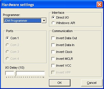
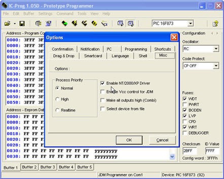
    Of course, there are a lot of other programmer/ debugger tools these days that you can buy for a few dollars but what about when you need to have a tool that you can use in multiple conditions. I was thinking of being able to have the same launchpad that I could use for both JDM programming for some old serial memory and for interfacing it with the PICkit or some other microchip dedicated tool. In this way, I would't have to create a test breadboard circuit every time I want to program something using my PICkit.

Challenges:

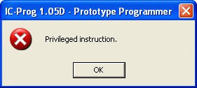
   I saw a lot of JDM tools and schematics, but I did not wanted to have something that gives those unending errors. I remembered a few years ago when I was starting a new PIC project, I had to spent half of a day to diagnose my PIC programmer and to see what is wrong whit it and then suddenly, It would start to work like magic and I could't explain this behavior. So I needed something reliable. I needed to use the MAX232 to make sure the signal levels are steady and every thing will go smoothly every time I try to program an old device.

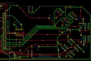
   Another challenge was that I wanted to have my PICkit connected to this launchpad from time to time and I had to come up with a way to have every thing hooked up.

Would even do a PICkit clone?

   I have a Chinese PICkit 3 clone and I remember struggling a lot to make it connect in the first place. After a while, I caught the secret of connecting it in a very efficient manner and since is not so complicated at all and it only takes a couple of minutes, I made a tutorial video to show others how to do it. 

JDM2.dip

Layout and schematic file for the Smart JDM programmer. To be opened with DIPtrace

dip - 224.75 kB - 11/07/2017 at 23:36

Download

  • 1 × 7805 Connectors and Accessories / Miscellaneous Connectors
  • 1 × 7812 Power Management ICs / Linear Voltage Regulators
  • 5 × 1uF capacitors
  • 1 × BC557 transistor
  • 1 × 2n2222 Discrete Semiconductors / Transistors, MOSFETs, FETs, IGBTs

View all 27 components

View all 2 project logs

  • 1
    Quick description

    1. Power switch for the launchpad half 

    2. DC connector for the input voltage

    3. RS232 connector for the JDM programmer

    4. Output connectors for the PORTB pins

    5. input connector for the PICkit programmer/ debugger 

    6. Programming socket 

    7. IR sensor 

    8. ADC input pot

    9. I/O to ADC switch

    10 PORTA pins busbar connector 

    11. PORTA switches

    12. Power LED

    13. PORTB LEDS 

    14. Launchpad socket 

  • 2
    Have fun blinking some LEDs

    I also posted a couple of tutorials for the sake of old times explaining how to write a short ASM code and how to program it into a PIC16F628 MCU and blink some LEDs. Only for those who are interested:

  • 3
    IC-rog settings for using it as a JDM programmer

    when the above message appears, go to the Hardware settings and select the following

    make sure to check the Enable NT/2000/XP driver tick box. 

View all 5 instructions

Enjoy this project?

Share

Discussions

Yann Guidon / YGDES wrote 05/29/2023 at 17:16 point

It's almost retro :-)

  Are you sure? yes | no

Marius Taciuc wrote 05/29/2023 at 17:58 point

Totally. Although this project was created in 2017, it's beginnings are earlier than that. I could find earlier versions of the schematic and some previous breadboard attempts. 

  Are you sure? yes | no

Yann Guidon / YGDES wrote 05/29/2023 at 18:38 point

I made my first JDM in 2003 or 2004...

Oh the memories.

  Are you sure? yes | no

Marius Taciuc wrote 11/09/2017 at 13:09 point

Yeah... Old memories. I was using pitch mixed in D500 paint solvent as an etch resistant two decades ago to make my first PCBs. I was also having a custom made pen.

  Are you sure? yes | no

Martin wrote 11/09/2017 at 12:59 point

Yes, indeed. Although I could not or did not want to afford FR4 Epoxy material as a school boy. I used some ivory colored FR2 or FR3 material (or sometimes the brown one) and rub on symbols for the ICs and mostly painted the traces with an etch resistant pen. A one-off PCB but I preferred it to perf-board.

Now I prefer SMD components and thanks to OSHpark and dirtyPCB plated vias are also affordable.

  Are you sure? yes | no

Martin wrote 11/09/2017 at 08:00 point

From the appearance this reminds me of my electronics projects (e.g. EPROM programmer) in the 1980ies. :-) Through hole components! The IC sockets!

  Are you sure? yes | no

Marius Taciuc wrote 11/09/2017 at 12:52 point

...and single layer PCB.      :P  cheers, mate! 

  Are you sure? yes | no

Similar Projects

Does this project spark your interest?

Become a member to follow this project and never miss any updates