 segasonicfan

Fortunately I came across this great Hackaday page by Patrick!
https://hackaday.io/project/9461-lifepo4weredpi
He was nice enough to answer questions and help me with my design. My previous 2 layouts were failures, shutting down after only <4.5W output.
I noticed the recommended inductors for this thing are >4A! for only 2A output current I thought this was strange.
Anyway, I designed this new proto board to run further testing. I'll report back!
So far I learned:
*CFF is not necessary. It is used for large transient load regulation. The recommended 10pf completely screwed up the output. A more modest 1pf seemed to work better (both 50v NP0 rated)
*Actual efficiency is closer 80-85%
*ILIM should be tied to EN if unused
*Ground loop layout is extremely critical
Questions I have so far:
Q: GND and PGND being separate makes me wonder if GND should be tied only to signal ground, i.e. the FB resistor? But the datasheet layout shows them joined so...that's what I did
Q: How will it funtion with a 3A-4A Inductor, rated 2.2uH?
Q: What is the actual sleep mode current draw?
Q: What is the EN pin current draw (wondering if a flip flop might actually be causing an issue driving this) though that seems unlikely


 t.oster92
 hesam.moshiri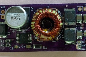
 Brian Cornell
 robert.c.baruch
woops, thanks for catching that typo. Cool, what are your takeaways from that chip? Did you get over 90% efficiency at any point?