 Patrick Van Oosterwijck
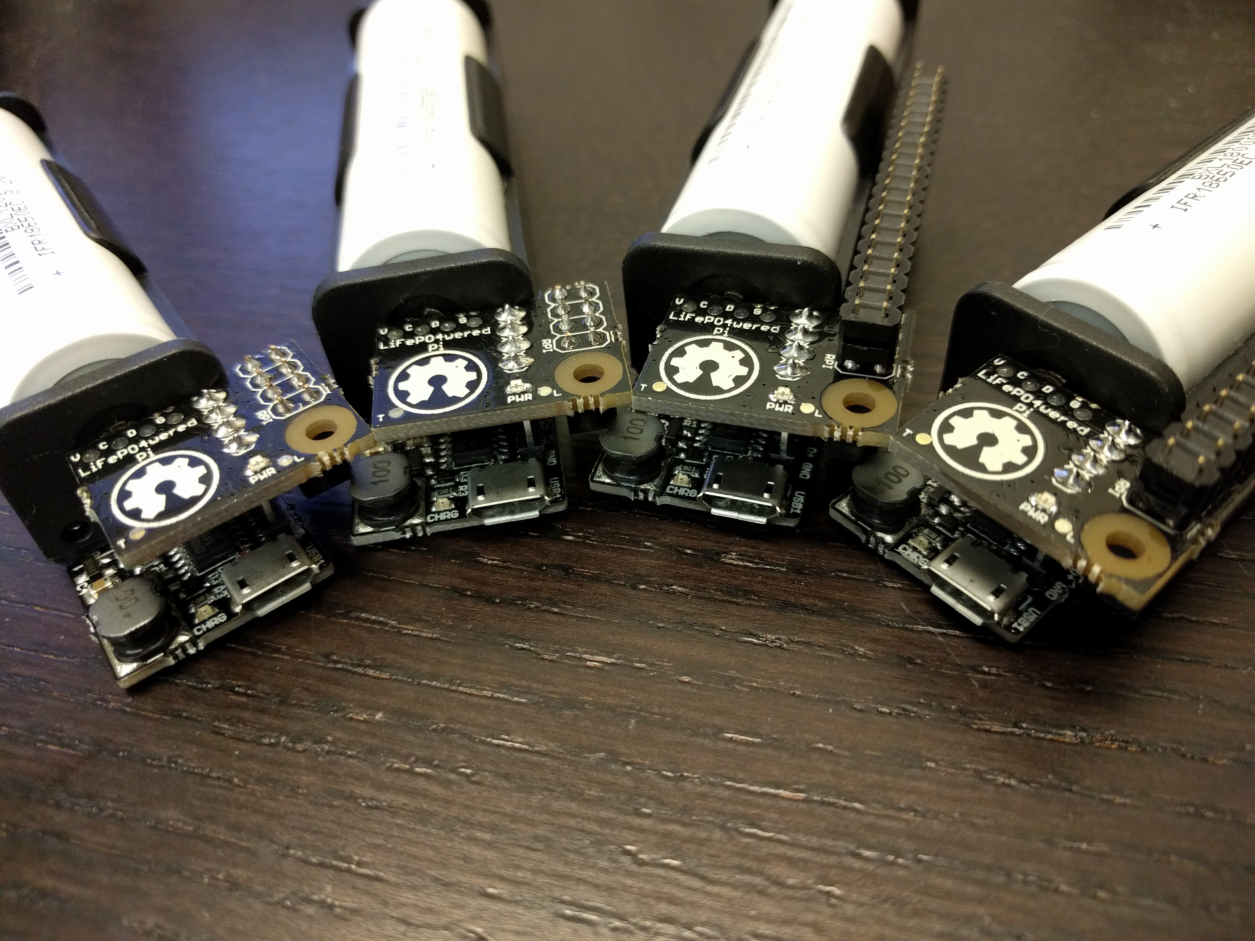
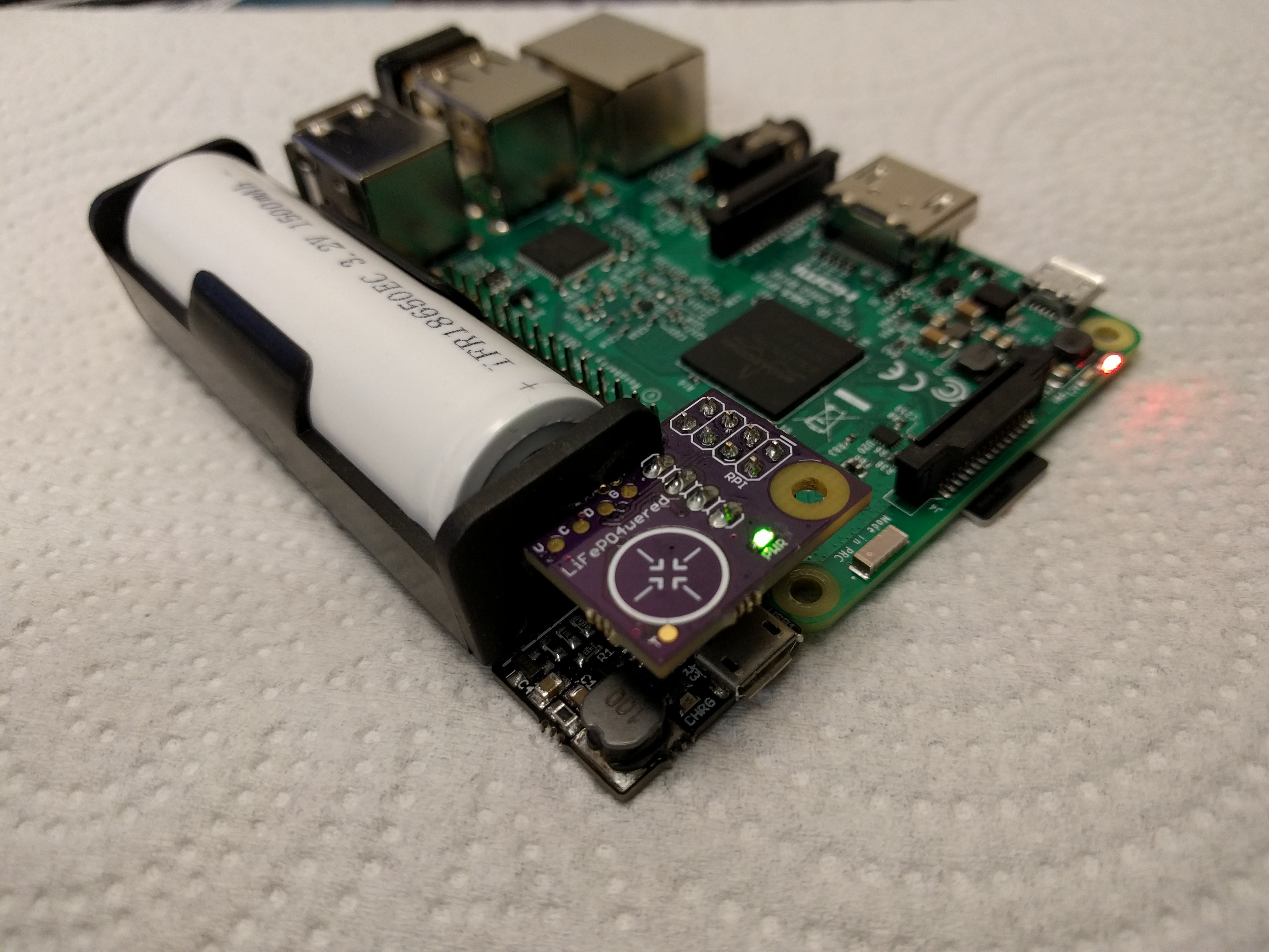
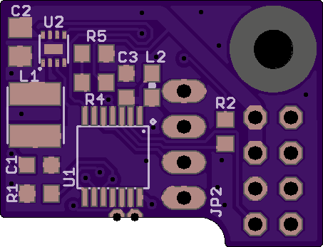
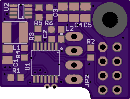
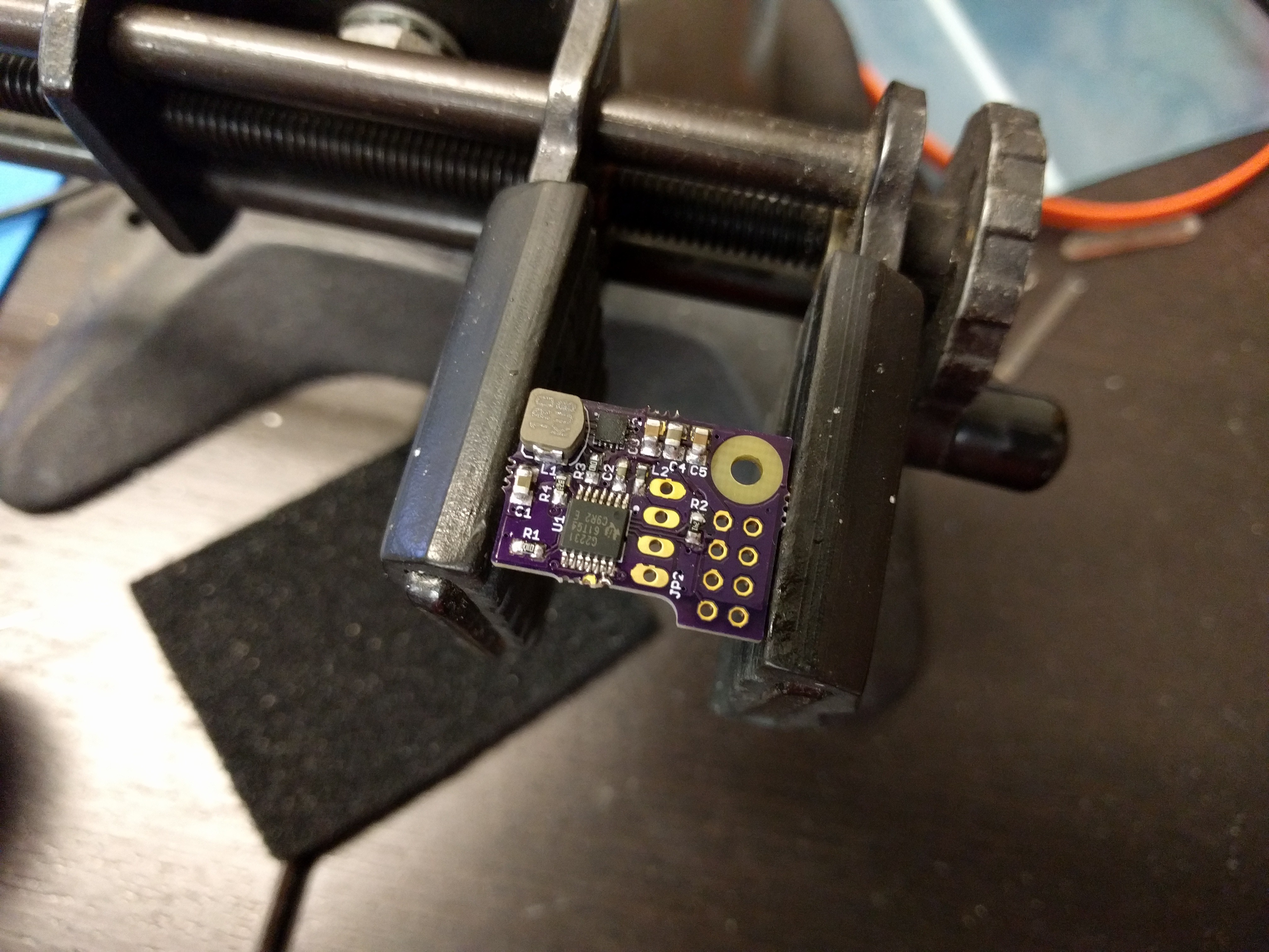
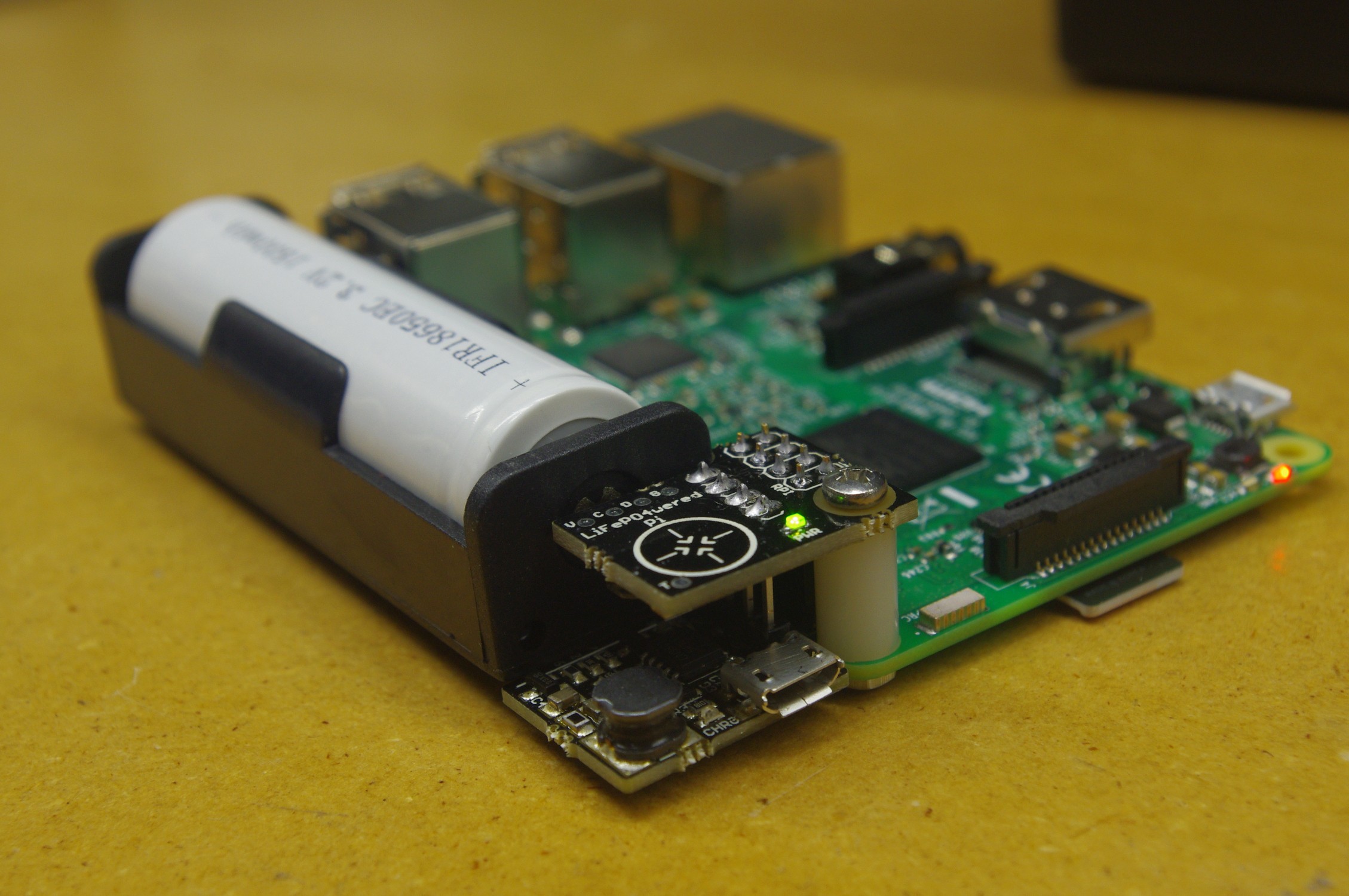
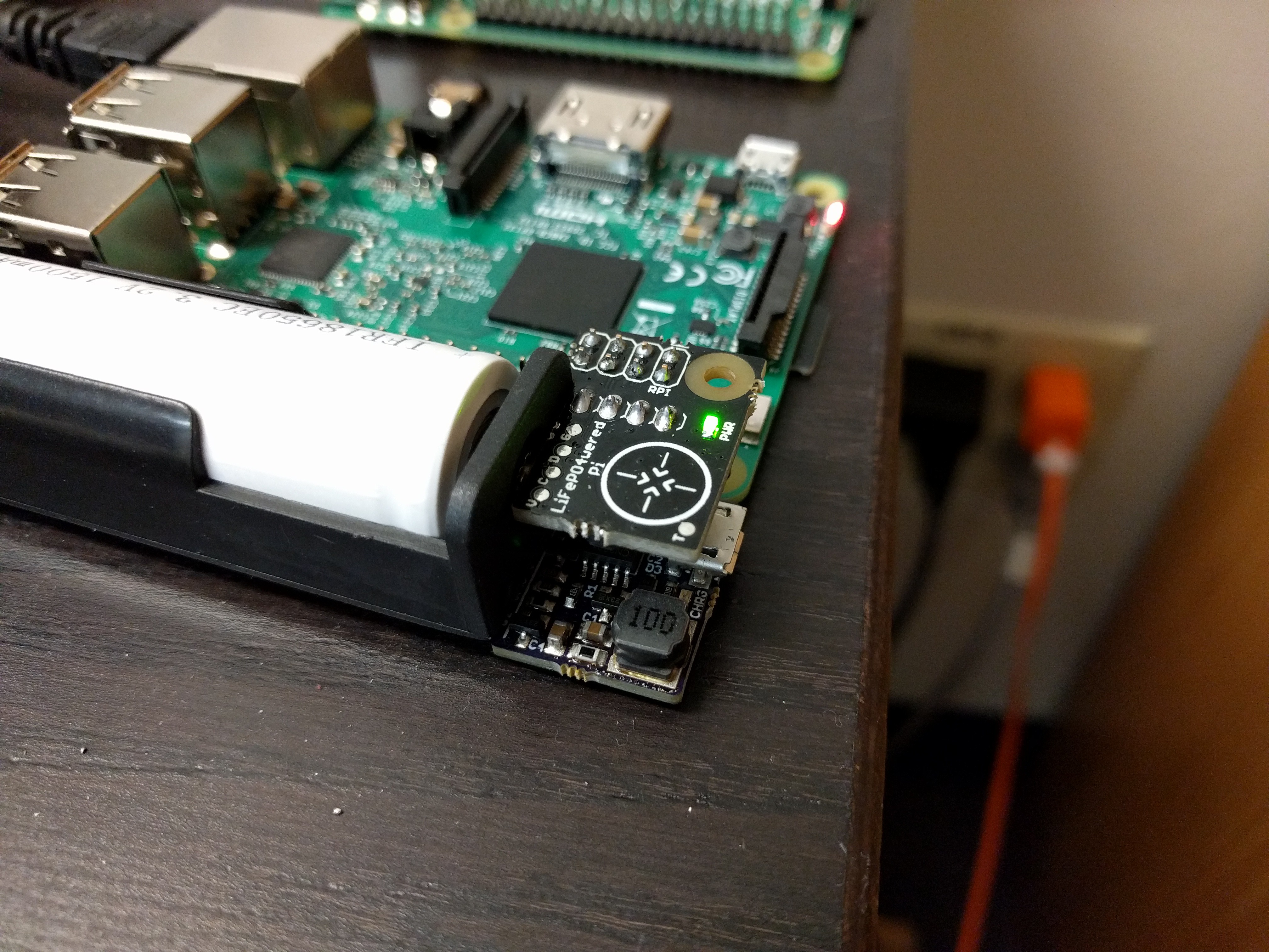
The project is built on top of a LiFePO4wered/USB or #LiFePO4wered/18650 module. A small board is added with an MSP430G2231 microcontroller that takes care of monitoring input and output voltage, monitoring a PCB touch button, driving a power indicator LED and switching the load (the Raspberry Pi power). The microcontroller is also connected to the Pi's I2C bus and monitors the Pi's running state. The small board connects to 8 of the Pi's GPIO pins but leaves the rest free to allow prototyping using fly leads.
An Open Source software package is provided on the Raspberry Pi to interact with the LiFePO4wered/Pi. It contains a library that can be used in your own applications, a CLI interface to read and write device registers over the I2C bus and a tiny daemon that continually tracks the power state, and can initiate a clean shutdown when the battery is empty or the user wants to turn the Pi off using the touch button. Touch button parameters, voltage thresholds, auto boot settings, wake timer and auto shutdown timer (#LiFePO4wered/18650 version only) can be customized by the user and saved to flash.
The touch button requires press-and-hold to turn the Pi on and off to prevent accidental activation. The power LED indicates several power states: off (LED off), busy with boot or shutdown (LED breathing), on (LED solid on). The LED also provides touch button feedback: fade on during the press-and-hold delay, fast flashes when the LiFePO4wered/Pi cannot comply with the user input, either because the input voltage is too low or the Pi is busy booting or shutting down.
Normally the LiFePO4wered/Pi will wait for the user to press the button before it will boot the Raspberry Pi. Auto boot values can be set over the I2C bus so the Pi will automatically boot whenever there is enough battery charge, or when the USB voltage is present (#LiFePO4wered/18650 version only). There is also a wake up timer that can be set so the Pi can shut down, and automatically be started again after the wake timer expires. There are separate, customizable thresholds voltage levels for when the Pi is allowed to boot and when it will be instructed to shut down, or even forcefully turned off in case the daemon isn't active or fails to shut down the Pi. This ensures stable operation and over-discharge protection for the battery.
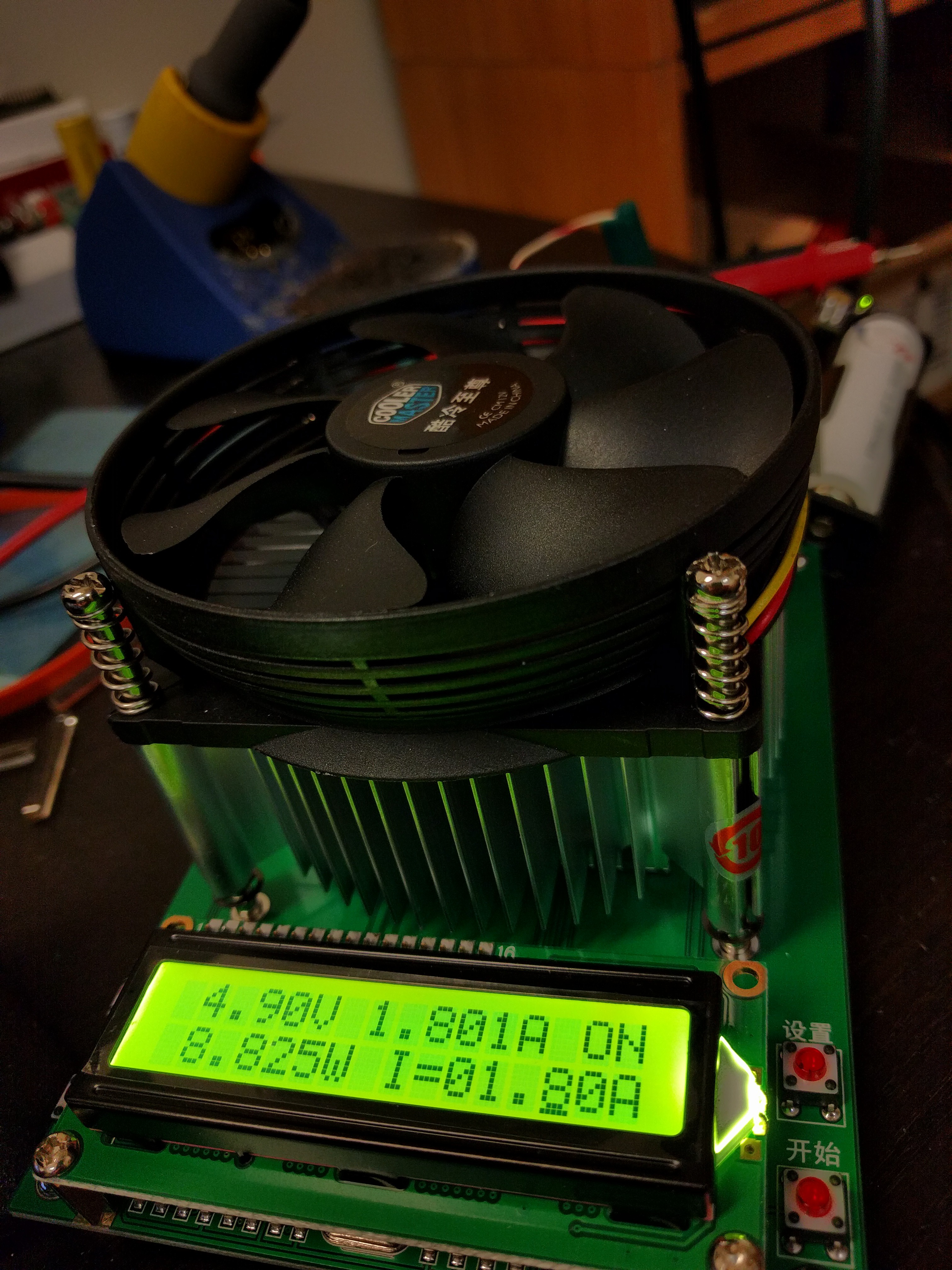
Based on testing with different Raspberry Pi's, a Model A+ and Pi Zero are able to run from the battery for over 2 hours. The B+, B2 and B3 take more power, but should be able to run for at least an hour. Run time will of course depend on system load as well. For UPS use, the #LiFePO4wered/USB based version is limited to low load conditions with the Pi Zero or Model A+, the #LiFePO4wered/18650 based version is recommended for UPS use in higher load conditions.


 Duane Benson

 TurkeyDev
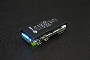
 Jdaie
Jdaie
Hey there, I've been following this project a little and I really like the end result! I wanted to ask whether your considered a design that would just piggyback off of the 5V rail on the Pi and kick in to provide power when the primary power is lost? Every battery backup system I see uses a separate charging port.