A Hacker's Wedding Centerpiece(s)
Im getting married :D. I've been put incharge of making the coolest* centerpieces ever!
(*coolest acording to me)
Im getting married :D. I've been put incharge of making the coolest* centerpieces ever!
(*coolest acording to me)
To make the experience fit your profile, pick a username and tell us what interests you.
We found and based on your interests.
yep one of my battery packs got very hot. and im franky lucky it didnt burn my office and house down. i was working on software, so i was not in my workshop with my electronics tools, i was testing the artnet firmware, things were going well. i decided to see how many nodes i could get running at once with what i had on hand. so i grabbed a few of the battery packs i had already constructed. but when i plugged in the first pack to the wemos board all the leds went .. "dead" .. i wonder if the lipos have drained to empty? lets try another one. still no dice. plug the wemos back into the computer: NOTHING!
so i must have accidentally done something. oops, it happens, move on. so i set aside the battery and keep working, an hour later the firmware is working well, time to get back to assembling acrylic spires, so i turn to the bag of m3 bolts...
yep it was a little warm. melted through the electrical tape, and the plastic of the ziplock bag. took the batteries out of the case IMMEDIATELY. one was warm to the touch. not hot, just ..warm. i still need to do some diagnostics to figure out what happened. but after this unfortunate incident ive revised my plan for the centerpieces. nothing is tackier that having your centerpiece burst into flames during the reception. I cant take the risk. so despite being against the hacker spirit. ill keep the lipos and boost boards for a future project and I've purchased 20 usb battery packs, from a reputable brand. this will really simplify my life going forward, because the hardware is basically finished. my wallet is cranky but who can put a price on piece of mind?
answer: me. its about $360
TL;DR: time synchronization is hard.
TL;DR 2: Keep it simple stupid
ive been working on the firmware for the modules. taking a page out of
I went a little overboard on the next part though. i decided "Why not make this multithreaded and have one process for each led ring? ill treat the entire strip as a shared resource and use locks!" it it didnt work half bad. I reminded myself of a lot of OS concepts from back in school. had a great time.
For all of this i used the uasyncio library from [peterhinch] . its pretty great and i was easily able to get different animations running on different rings of the centerpiece, even though it was all on the same "strip"!
the striped down version is available for reference as a gist.
In truth if i only needed one centerpiece, id be done. it works great. the problem came when i loaded this onto half a dozen items at once. due to...physics (temp differences, crystal inaccuracy, you name it.) ... every esp8266 ran at a slightly different speed making things slowly drift out of sync. this was especially annoying when trying to strobe or blink every centerpiece at once.
Ill be honest, i spent weeks on this. i read RFCs i implemented NTP sync options. I couldn't overcome the inherent latencies of the system. one day i looked at the code base and saw that almost 40% of the lines were due to synchronization. i was pretty disheartened; I had started with an elegant solution (heaven save us from elegant solutions). but to support that elegance i had put so much lipstick on the proverbial pig....not really sure where that analogy goes...
I had to take a step back and come at this from a different angle, but, with the wedding getting closer i began to worry a bit.
then inspiration struck and i realized:
why am i letting these dumb nodes decide their own timing. i should just send every step of the animation and let a server decide the timing. this revalation came about as i was picking up some theatrical lighting from a friend, and reminded me there is already a networking protocol for "intelligent" lighting named artnet. i had never used it before.
and i said to myself:
"Surely it is far to heavy weight to run on a microcontroller!" nope its a UDP packet.
"Surely ill have to implement this myself, right?" nope its been done.
"I bet the lighting control software will cost a fortune. ill need to write a quick and dirty driver." nope FOSS is pretty all encompassing
it only took about 2 hours to hook up everything. lesson learned. keep it simple.
now i just need to finish the battery packs! ...what is that burning plastic smell...
well that could be a problem.
To Be Continued....
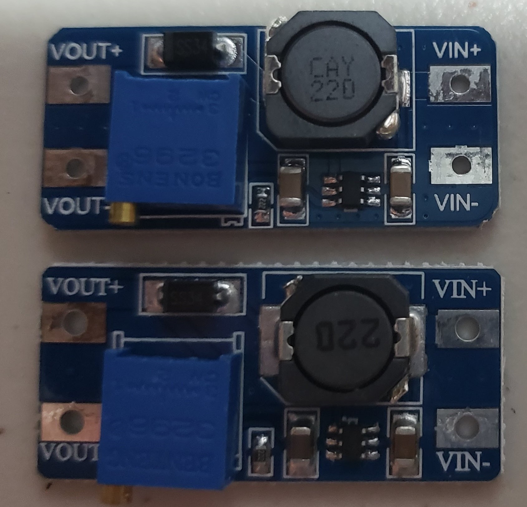 |  |
One of these boost converters works, the other appears to not work. can you spot the difference?
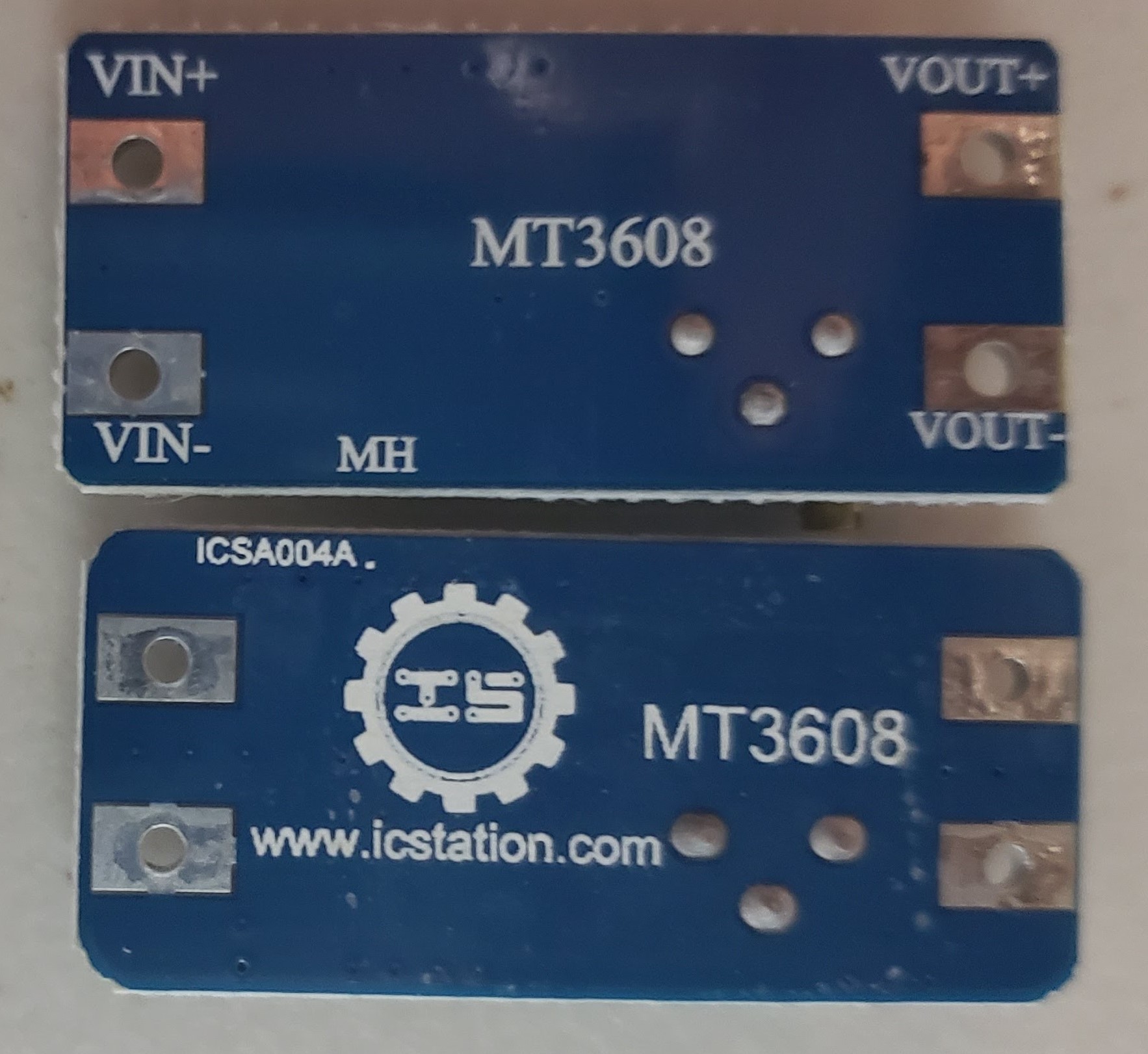
the centerpiece could draw a peak of 750mA. so ive been in search of a boost converter to take a Lithium ion pack at 3.7V nominal and boost it up to the 5V for the APA102 addressable Leds. i bought a few candidates on ebay and tested them out. i really liked this one based on the MT3608 step up converter by aerosemi. its dead simple and should handle 2 amps max. so i bought 20 from aliexpress and when they arrived set about to test them all; and Every Single One FAILED.
As a teacher, if one of my students came to me and said 20 units all were broken...i'd be skeptical to say the least. so i brought in a friend to double check my setup, both of us agreed they SHOULD work. but it was obvious that the IC was not switching, and therefor the inductor was at DC. so 3.7V was present at Vin. and there was a small drop at the diode.
My first guess was the IC; was i counterfit? was it ESD damage? so i exchanged the ic's from the working board to the dead board and vice-versa. No change, in either board. the one that used to work still worked. the one that didnt work continued to not work. we went down the list of components
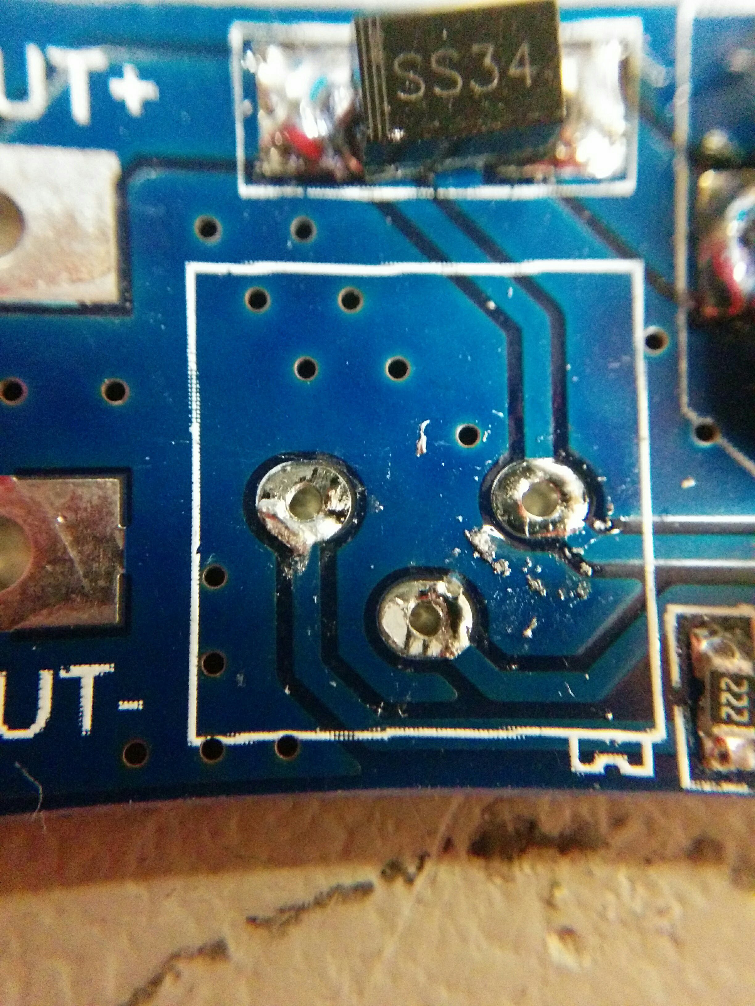 | 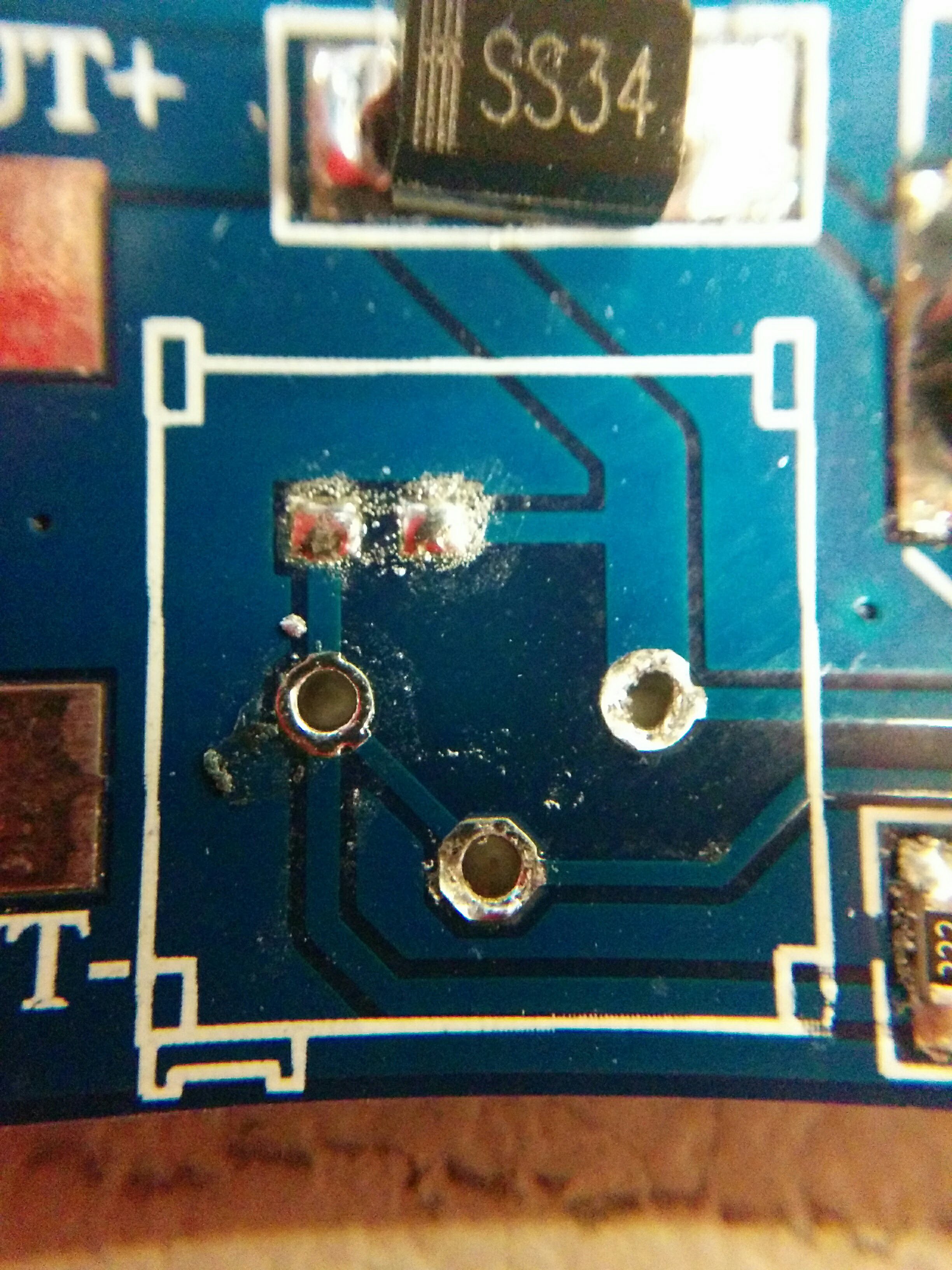 This one always worked |
Well that's different what the hell is going on?
I removed all the items from both the working and non-working boards then reverse engineered both boards into eagle.
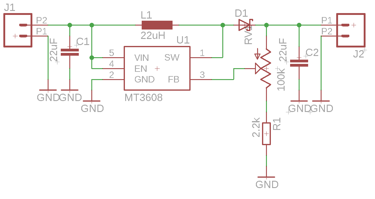 |
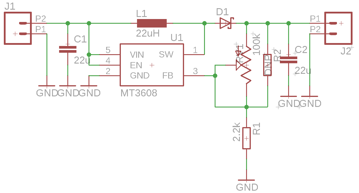 Functional 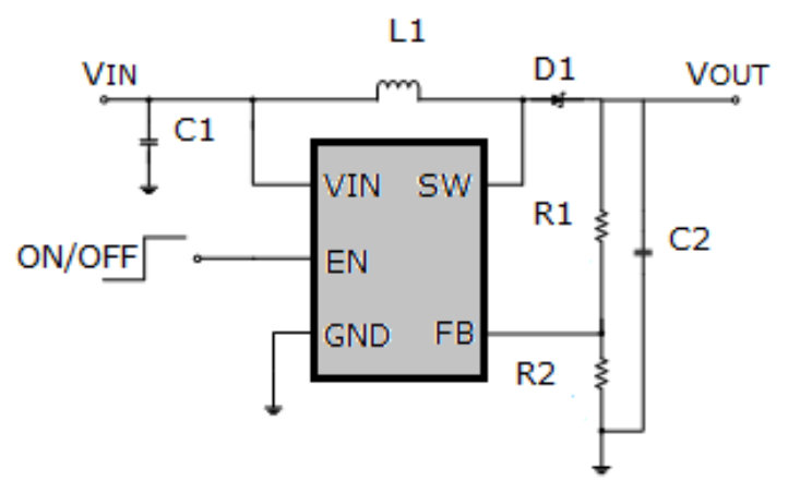 Application circuit from the datasheet Application circuit from the datasheet |
The obvious difference between the two is one uses the potentiometer as a three terminal device and the other uses the potentiometer as a rheostat. On the surface this didn't really seem to explain the problem.
so in either case
This basically matches with the data sheets min and max voltages.
at this point my friend let me in on the secret. let me illustrate using wolfram alpha to plot the output voltage as a function of the percentage of the pot from off to full.
and there it is as plain as the nose on my face; the "working" one has a linear response over the 30 turns of the potentiometer. but the "non-working" version presents an exponential response basically it wont even turn on until you're 85% on.
In the end it wasn't cheap manufacturing or counterfeit parts; it was a PEBKAC error. All i needed to do was turn the pot another 20 turns and i began to see the converter boost up to my required voltage. i prefer the linear response though so shorting the two terminals of the the potentiometer nicely solves that problem.
with that out of the way I can now run the entire centerpiece off of battery power.
more on how i created this in the next post
now that ive had the breakout boards populated and wired ten in a chain, i need to have some kind of test code. having more than one led means that now i want to have more than one color displayed.
the first prototype code had 4 bytes per data-gram "RR BB GG VV" red, blue, green, intensity value. and that color would be displayed on all leds. now, ive just duplicated that project. every group of 4 is one led, therefore 10 leds should take a 40 byte data-gram. not an earth-shattering bandwidth.
Interpreting the data was straightforward. i used a quick function to chunk the data into 4 byte arrays....thats it. everything else is the same as dealing with one led.
from machine import Pin
from apa102 import APA102
import usocket
port = 5500

clock = Pin(14,Pin.OUT)
data  = Pin(13,Pin.OUT)
numPixels=10
apa = APA102(clock,data,numPixels)


# https://gist.github.com/SZanlongo/f9290809d1f76289d40a52af949acfbc
def chunks(l, n):
    """Yield successive n-sized chunks from l."""
    for i in range(0, len(l), n):
        yield l[i:i + n]


def setPixelRaw(index,r,g,b,val=31):
  apa[index]=(r,b,g,val)

def setPixelStr(index,s):
  if len(s)<3: return
  val=31
  r= s[0]
  g= s[1]
  b= s[2]
  if len(s)>3: val = s[3]
  setPixelRaw(index,r,g,b,val)


s = usocket.socket(usocket.AF_INET,usocket.SOCK_DGRAM)
s.bind(('127.0.0.1',port))

while True:
  t=s.recvfrom(1024)
  l = t[0]
  for i,x in enumerate(chunks(l,4)):
    setPixelStr(i,x)
  apa.write()
then i needed some cute animations. i need to clean up the code a bit but the colorsys library comes to the rescue again.
i think with this successful test i need to lock in the dimensions of the acrylic and spin up the final base pcb.
quick update!
breakout boards are in, i got white soldermask because...reflective?...cool factor?... cool factor.
huge shout-out to dirtypcbs who has always handled anything i threw at them no problem.
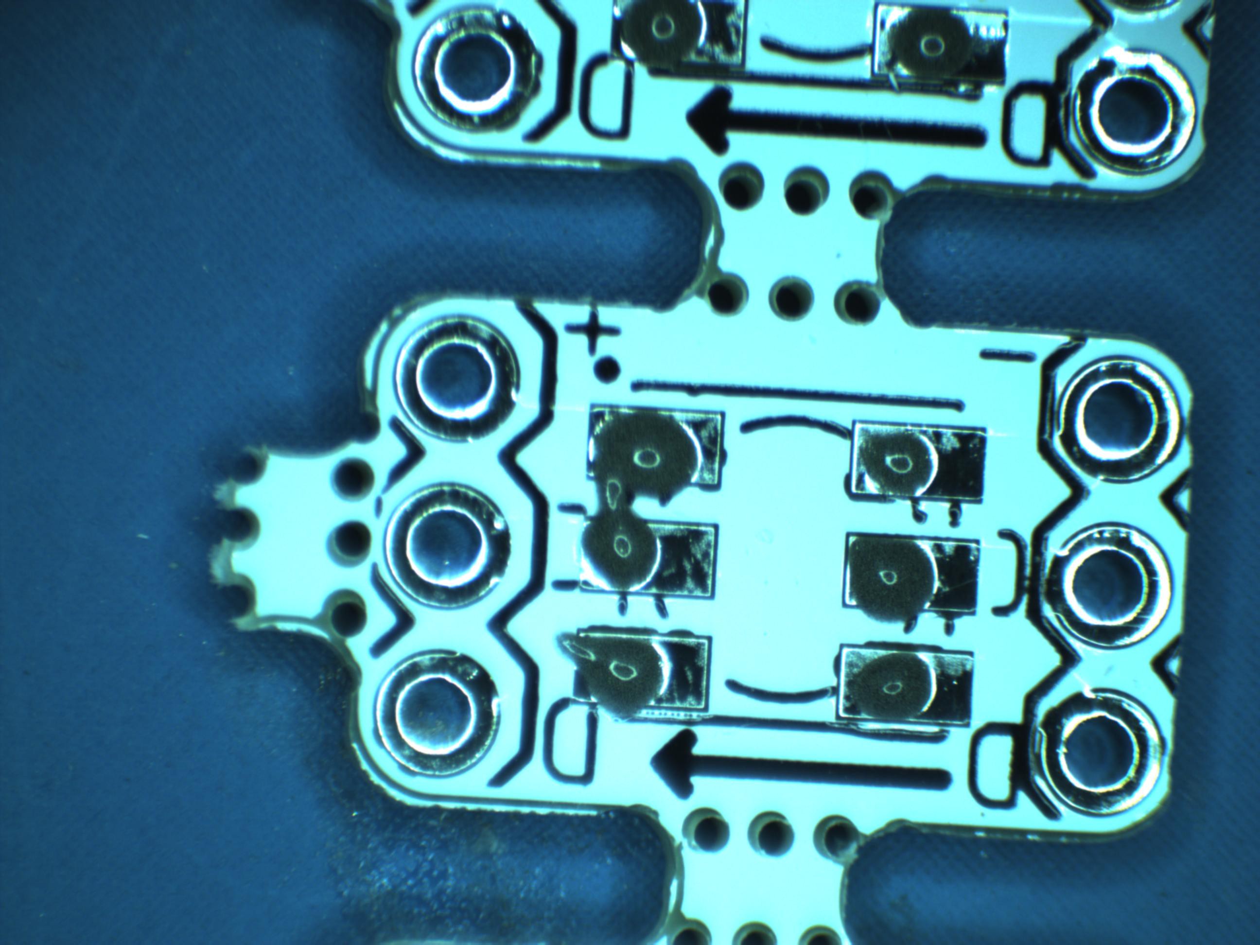
i quickly found my first problem. the footprint is not really hand solder friendly. does anyone have any application notes or white papers on how much is enough when it comes to making hand solder-able footprints?? eagle has two different 0805 footprints one is easy to hand solder, the other is impossible. i ruined 3 breakout boards/leds then abandoned my hand iron for a solder paste dispenser and re-flow oven.
i have a 983A solder paste dispenser and a T962A reflow oven in my lab, so i popped over and made up 40ish.
that's where i discovered my second mistake, the footprint was upside down, the pin one marker is in the wrong spot, everything else was labeled correctly so, not a big deal.
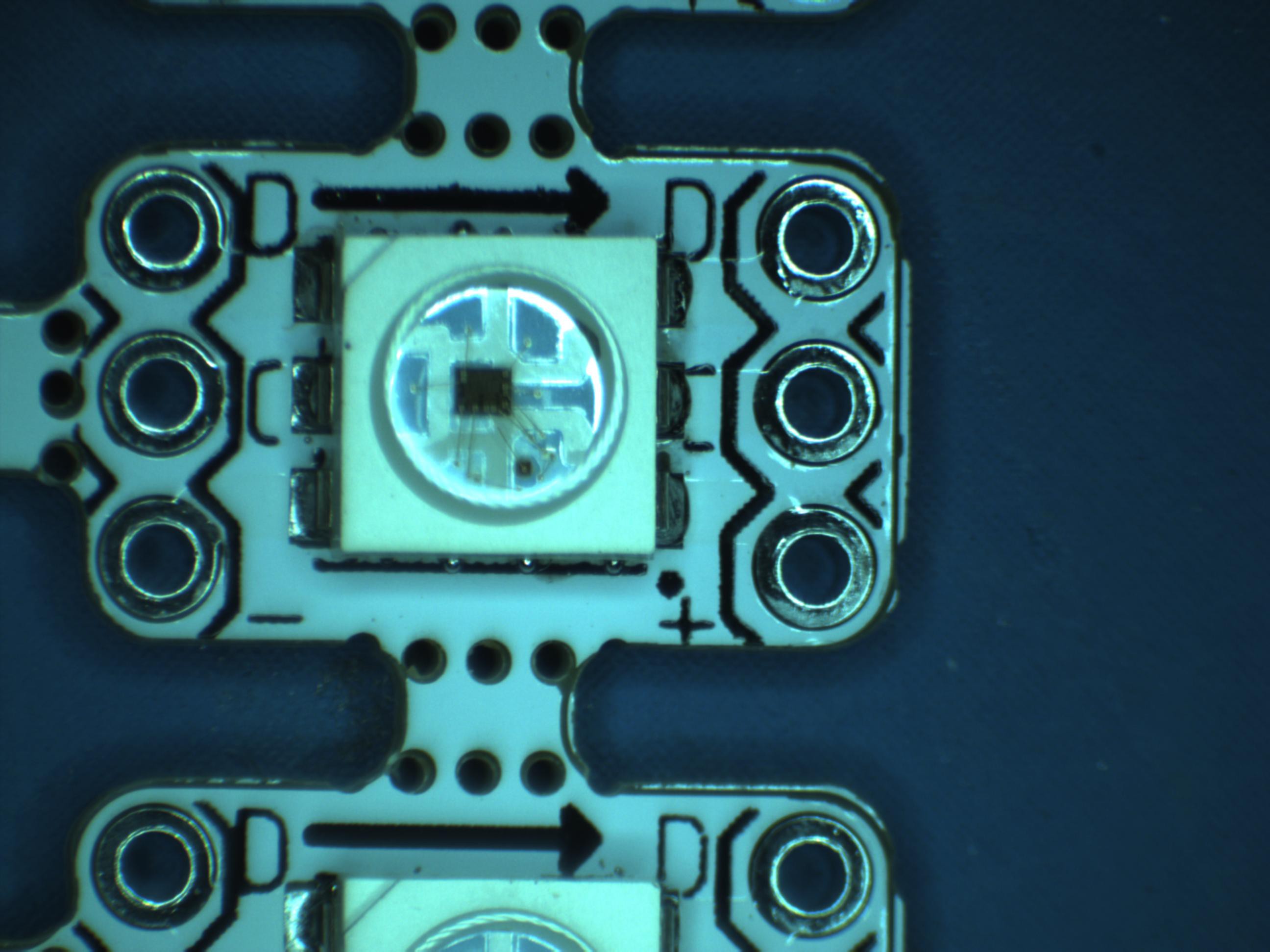
i was concerned about the leds surviving the reflow, they seemed very heat sensitive, any contact with a iron would destroy them, i used the default profile on my reflow oven and set out to test them.
 |  |
I modified some example code to light 3 leds in a strip, two were already available from previous tests, and the first would be the device under test (DUT). i set up the bread board with some double length headers to hold the DUT.
rom machine import Pin
from apa102 import APA102
import time

clock = Pin(14, Pin.OUT)     # set GPIO14 to output to drive the clock
data = Pin(13, Pin.OUT)      # set GPIO13 to output to drive the data
apa = APA102(clock, data, 3) # create APA102 driver on the clock and the data pin for 8 pixels


while True:
    apa[0] = (0, 0, 255, 31)
    apa[1]=  (0,255,0 ,31)
    apa[2]= (255,0,0,31)

    apa.write()                  # write data to all pixels
    time.sleep_ms(500)

    apa[0] = (0, 0, 255, 0)
    apa[1]=  (0,255,0 ,0)
    apa[2]= (255,0,0,0)

    apa.write()                  # write data to all pixels
    time.sleep_ms(500)
Each led was friction fit onto the double length headers. if all three leds blinked i reasoned both input and output pins on the led worked well. i didn't have a single failure.
ill leave you with a shot of the apa102 die, not a super magnification, just interesting. next i have to wire ten of these up and set them up under the acrylic.
500milx300mil
that is the size of my APA102 breakout board. (call it 13x8 mm) and with DirtyPCBs I can have 100mm x 100mm so panelization is a must. opening up GerberPanelizer by ThisIsNotRocket Science the first step is adding as many breakout boards as possible.
i use the naive autopack feature to get a clean grid of 60 boards, now i need to add breakout tabs. thats alot of tabs lets see what the auto breaktab feature does?
ok, that was a bit more than i anticipated. time to get creative
i am going to place two breaktabs precisely where i want them in opposite corners and save the file.
if focused on placing the tabs exactly in the middle between the two breakout boards and at the midpoint of the boards. this is important because any errors at this stage will propogate through the process. next open the file in notepad++. its simple xml we want to find the tabs section.
and now this is all we need is some quick division and then copy and paste. there are 5 spaces between columns in the x direction:
(80.4-6.4)/5=14.84
thats all that need to be added each time. same formula for the y direction.
first i check the distribution across the x axis, add 5 lines
save the file and reopen it in gerber panelzer
i consider this a huge time savings, and it makes the tabs much more repeatable. repeat this for all the long edges and the narrow edges and we arive at the final panel and only four had to be placed manually.
Thats it for panelizing and its been sent off to Dirty PCBs so in just a week or two ill have 600 breakout boards. ready to prototype with.
Up till now I've been prototyping with individual 5050 apa102 leds, and to wire them up I've co-opted some soic8 to dip8 breakout boards. that is not going to work in the long term. also as a contigency plan, if i run short on time id like a way to throw the leds into a quick laser cut 'form' and use that as part of the final piece, it will be messier, but i can hide any wires as needed, so i set about to create some easy to use apa102 breakout boards, cheaply.
i always try to make my own footprints before trusting anything i find in eagle. 95% of the time, everything works if you use stock components, but Murphy's Law makes that 5% of the time happen every time... so off to the data sheet. Aliexpress had some mechanical drawings on it:
ok the componenet has 1mm x 1mm contacts, then there is 4.2mm outside to outside dimensions so the center Y value would be: divide by 3 and.. no (4.3mm-3*1mm) /3 +.. <opens Skectchup> <30 seconds later>
ok now i know where every pad is. i just need to know the recomended pcb footprint. and thats where i cant follow this datasheet, it indicates 1.5mm wide, but not where is should start nor how tall it should be. doing a quick internet search for "apa102 datasheet" yields plenty of datahsheet but not much more. "apa102 footprint" or "apa102 land pattern" dont help much more. so lacking anything more substantial ill settle for any 6 pin 5050 led.
"5050 led land pattern" on image search hits paydirt.
will this work with my APA102s? lets just remake this in sketchup too.
And it was at that point im reminded of a recent hackaday article "terrible dimensioned drawings" but that being said, im going to use it anyway. the error shown is 0.15mm and all the dimesions listed for the led contacts are +/- 0.1mm. like homer said "close enough."
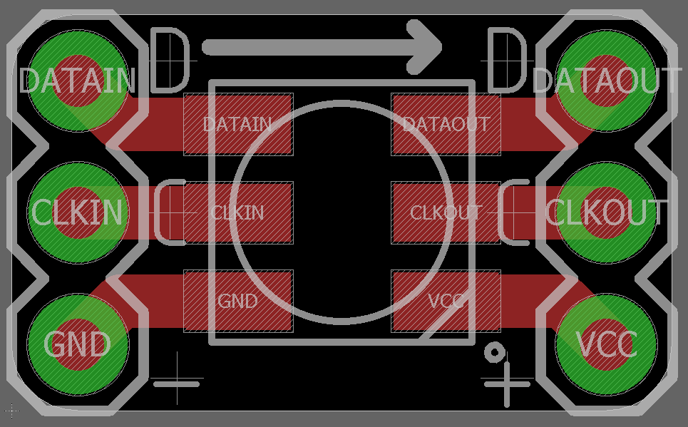
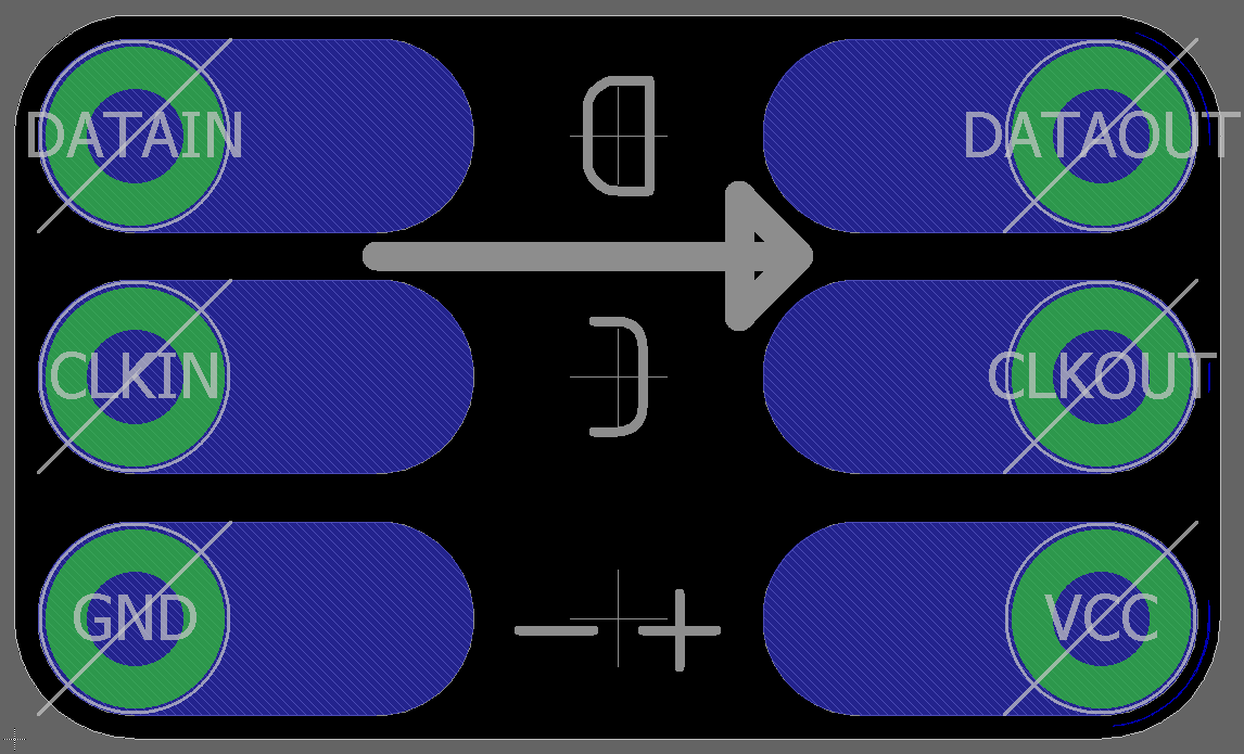
onto eagle, very basic.
 |  |
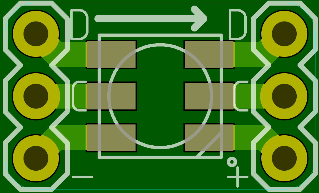 | 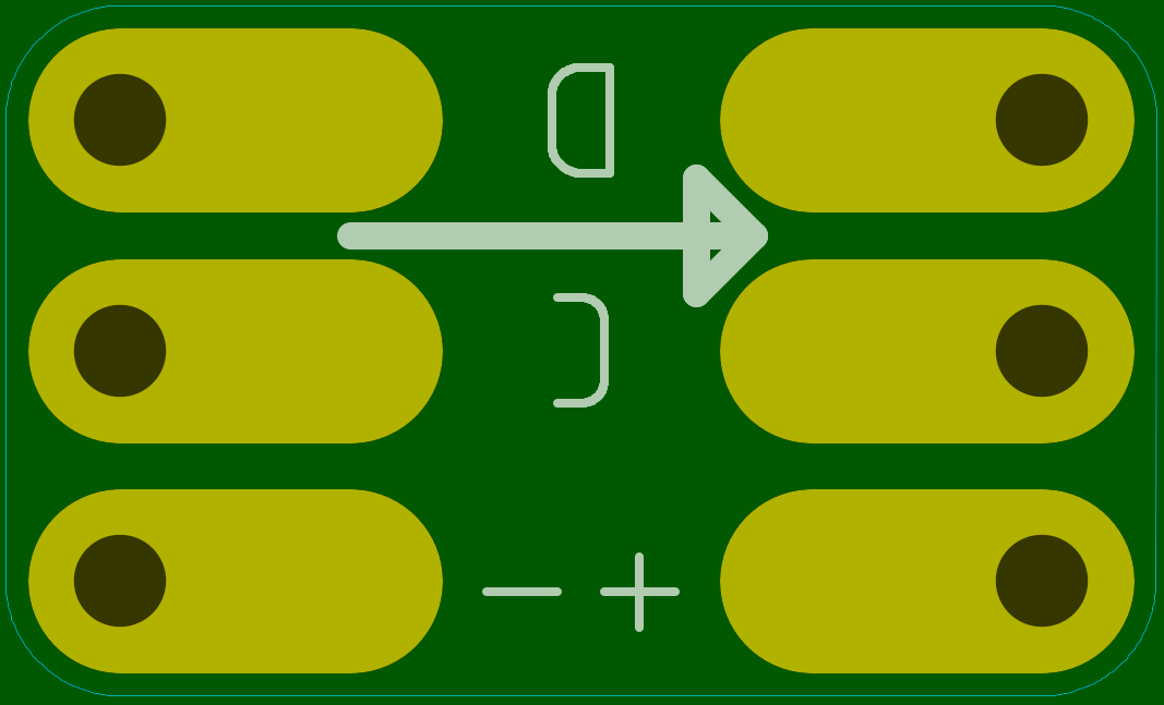 |
the only hacky thing i dis here was add giant traces on the bottom so i could solder wires invisibly and chain multiple wires together the bStop layer will stop soldermask from being put down. after checking the gerbers in gerbv, i set about to panelize the boards.
and, since i did something beyond just running ThisIsNotRocketScience's Gerber Panelizer ill stop this post here.
preview of next time:
since there will be many centerpieces and i want them to be syncronized in whatever they are doing i was originally thinking of a RFM69 module running some kind of mesh network. i got some from my favorite chinese superstore, and played with them for roughly an hour and decided that would be kinda a pain in the a**. instead i turned to a slightly less energy efficient item the ESP8266.
In short it uses a bit more current, but take on the role of both processor and wireless tranceiver, plus python. its the path of least resistance for me. so i took the wireless "strip" i created several entries ago and hooked it up to some nodeMCU modules i had lying about.
i use the built in python binding for the apa102 and connect the CLKIN line to GPIO14 and the DATAIN line to GPIO 13.
technically i should use a level converter, but at the prototype stage it works okay. so ill leave it for future me to sort out.
and thats the hardware completed for this post.
The software
ive decided to try using UDP broadcasts for this project, it will syncronize within the latency of the network, and that is negligible on the timescales im working with. ill have to build up a protocol layer on top on UDP but i dont need to worry about reliable communications since i can accept a certain amount of frame loss in the transmission.
for a test program ive decided to transmit a 3 byte datagram in RGB order. when a node receives the datagram it will set all leds to the transmitted color.
Receiver code:
im currently running micropython, but i may switch to circuit python at some point if i run into any problems.
from machine import Pin
from apa102 import APA102
import usocket
port = 5500

clock = Pin(14,Pin.OUT)
data  = Pin(13,Pin.OUT)
numPixels=2
apa = APA102(clock,data,numPixels)


def setPixelRaw(index,r,g,b,val=31):
  apa[index]=(r,b,g,val)


def setPixelStr(index,s):
  if len(s)<3: return
  val=31
  r= s[0]
  g= s[1]
  b= s[2]
  if len(s)>3: val = s[3]
  setPixelRaw(index,r,g,b,val)


setPixelRaw(0,255,255,255)
setPixelRaw(1,255,128,64)

apa.write()

s = usocket.socket(usocket.AF_INET,usocket.SOCK_DGRAM)
s.bind(('127.0.0.1',port))

while True:
  t=s.recvfrom(1024)
  setPixelStr(0,t[0])
  setPixelStr(1,t[0])
  apa.write()
that is it for now, in the future id like to be able to send different rgb values for different pixels. but seeing as how i only have two leds wired up at the moment this will do to test the wireless aspects.
Transmitter code
The transmitter code currently runs on my laptop. on a full python2.7 interface. this is likely how the final version will run; a full python interface, not my laptop, maybe a Raspi or Beaglebone.
Using the full python interface simplifys the HSV to RGB conversion significantly, "import colorsys" does it all. <insert XKCD comic here>
the only special part of this code is the socket option SO_REUSEADDR for broadcasting to the local subnet.
import socket
import binascii
import colorsys
import time

udpIP = '10.0.0.255'
udpPort = 5500
color = "7f3f1f"
message = binascii.unhexlify(color)
sock = socket.socket(socket.AF_INET,socket.SOCK_DGRAM)
sock.setsockopt(socket.SOL_SOCKET, socket.SO_REUSEADDR, 1)

sock.sendto(message,(udpIP,udpPort))

while True:
  for i in range(256):
    (r,g,b) = colorsys.hsv_to_rgb(i/256.0,1,1)
    r=int(r*255)
    g=int(g*255)
    b=int(b*255)
    message = chr(int(r))+chr(int(g))+chr(int(b))
    sock.sendto(message,(udpIP,udpPort))
    time.sleep(.01)
now to focus on having more LEDs to play with...
Last post wrangled fusion 360 into creating some acrylic pieces, but getting these pieces fabbed is a different challenge.
the design is intentionally split into just 4 components duplicated multiple times.
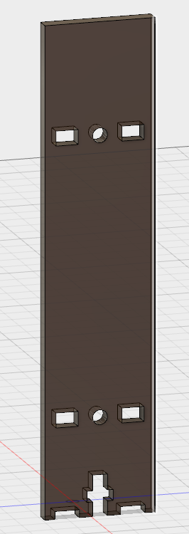 | 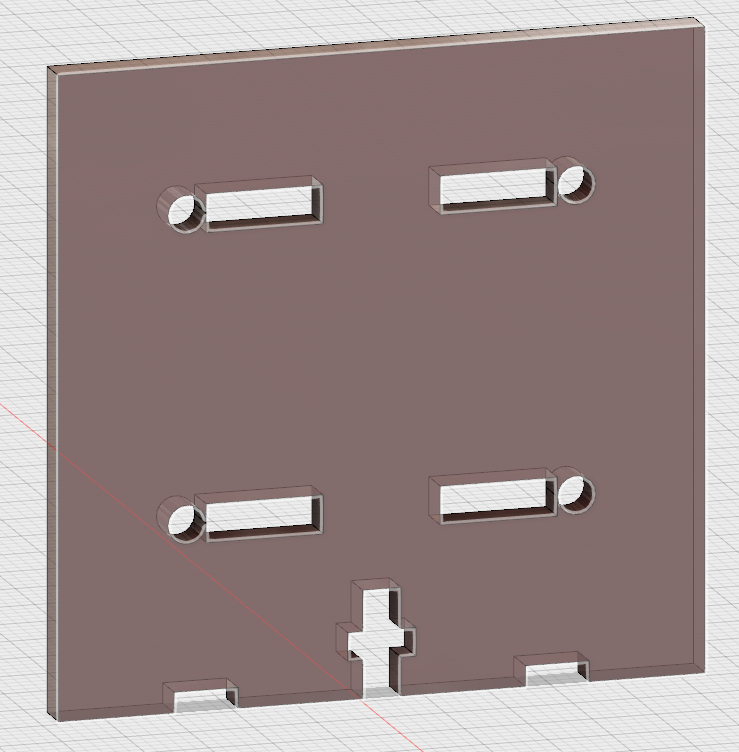 | 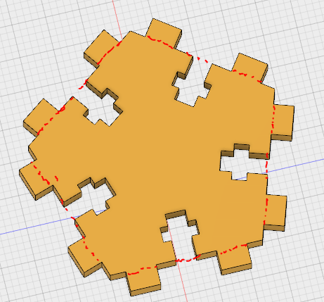 | 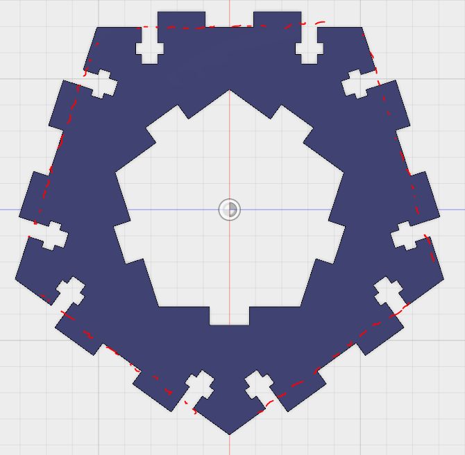 |
now i needed to get these to my laser cutter. a Chinese import 300x500 with an Rudia controller.
The software on these machines is notoriously ... not great ... but ive gotten used to it at this point. all i need is a dxf file to send to the software and ill be happy at this point.
so, fusion360 can do this pretty quick!
the cam tool can work with laser cutters and with an extra plugin, written by autodesk, it can make dxf files.
so im going to create 4 different "setups" one for each of the pieces i need to cut.
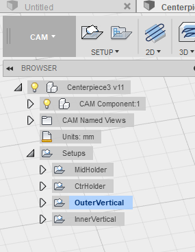 |  |
for the vertical pieces, i need to tell fusion to perform two separate cutting operations.
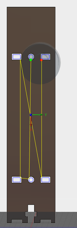 notice the cam has accounted for the laser kerf | 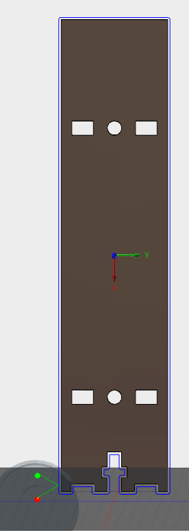 notice the cam has accounted for the laser kerf |
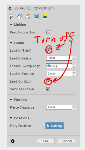 |  |
only one piece threw me on this part. on the outer cut, notice the green lines coming from the start and stop points? that's called lead-in in fusion 360. if you have tiny holes, you need to turn this off otherwise the cam processor can't make it work. so, thats a thing...
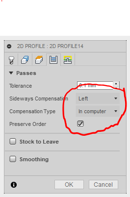
Also for the DXF export it is important to choose the correct kerf compensation selection. you want to choose Left compensation and "in computer" the dxf post processor cant handle the "in controller" option.
as ive been designing this model ive forgotten my laser cutter kerf, but thats ok i can change one parameter and the cam processor will compensate.
since i was trying to test construction methods with this prototype i set the parameters to relatively small. after running the post processor and importing into RDworks I've sent it to the laser cutter.
and assembled.
this version went together SO much better. also, as an added bonus, the center has been filled with 4.5mm rhinestones, for that extra sparkle.
i hope the next post will talk about the wireless transmission aspect.
well this took alot longer than i thought.
i had set out to make a second revision of the acrylic that would adorn the circuit board, but the cad cam process just took to long.
steps 2 through 6 took several hours. once was enough. i thought, there must be an easier way, so i embarked on a journey to learn fusion 360. four days later and a lot of head banging later, i emerged with a pretty good handle on fusion 360 and a workable parametric model of my centerpiece.
This project was just complex enough for me to really have to get into the details of this cad program.
The Base
the base of the model shows the PCB and the outlines of where the acrylic will eventually go. and everything on it starts with a sketch.
just about everything has been made a user parameter. ive placed two inscribed polygons centered on the origin, the side length of both has been set to user parameters (in the image above 55mm and 27 mm). ive also placed points where bolts and leds will eventually end up. that is for this sketch.
next i designed a quick bolt and led to nominal dimensions.
The rotate operation
this one operation is the focus of the entire model.
first i place a bolt and two leds for one panel. they are locked to the points on the parametric sketch i made for the base.
then grab the bolts and leds and rotate!
now its time to build up the acrylic
The Acrylic
back to the drawing board...well actually back to the sketch. fusion360 keeps everything you ever do and the order you do it in (this will become important in a minute). we make a new sketch with two rectangles. they are linked to the pentagons in the base sketch.
we can use the same user parameters we have used before for the side lengths. i also cut off a bit from each corner so the acrylic doesn't overlap. then extrude!
now i COULD just repeat the same rotate operation i used for the bolts, BUT a better option would be to TIME TRAVEL!!!!!
i did mention that fusion 360 stores everything you ever do and when you do it, what i didnt mention is that you can go back in time and modify little parts of what you did in the past. you can even take some things that you did in the future and bring them past.
so to simplify my life (and trust me, it does simplify things) i dragged the sketch and extrude operations before the rotate operations as shown above. Then, i edited the rotate feature to include the acrylic. then i warped forward in time, everything is redone in order.
we will need something to bolt the acrylic together however. add another sketch.
in none of these sketches do i worry about kerf whatsoever. this would result in very loose fitting parts but i will be dealing with the kerf in a later stage. based on the two holders i made i used joint offsets to palace them centered on the circuit board at fixed heights.
now i add in the modifications to allow these pieces to fit together by adding a sketch to the extruded face of the acrylic.
all of the dimensions come from user parameters. then i do another extrude THROUGH the existing acrylic and cut holes for the tabs,bolts,and leds. Also, since i moved the sketch back in time to before the rotate operation all of the cuts propagated through.
this post has gone on pretty long at this point. ill cover laser cutting this design in another post.
Create an account to leave a comment. Already have an account? Log In.
[this comment has been deleted]
Become a member to follow this project and never miss any updates
 charliex
 engunneer
 Dominic
 Matthew Peverill
Thats pretty devious, i like it, time permitting...