0%
0%
SHTTTRRR
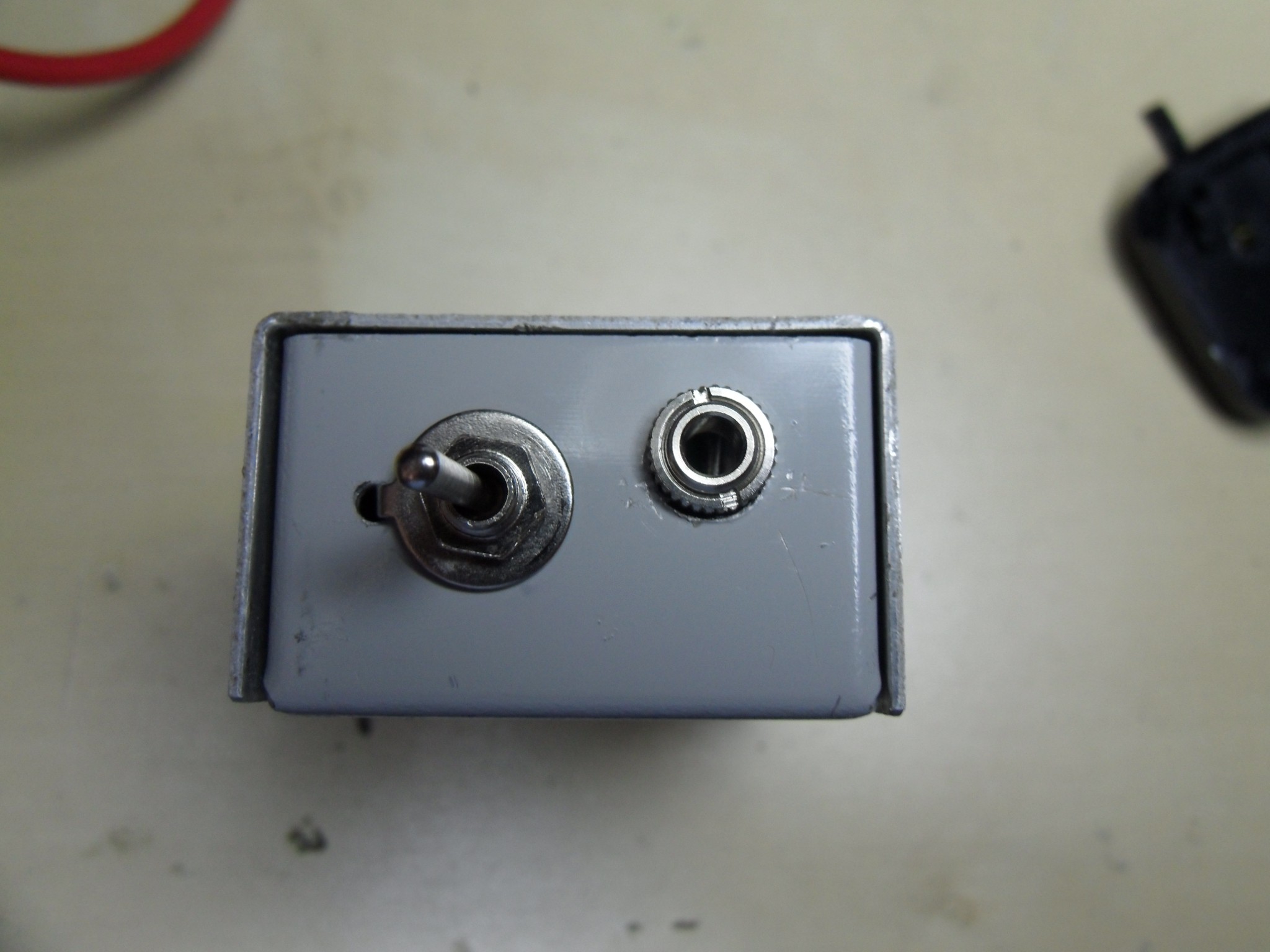
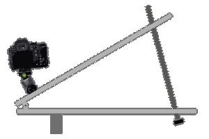
A small shutter controller for Canon EOS Cameras
Become a Hackaday.io member
Already have an account? Log in.
Just one more thing
To make the experience fit your profile, pick a username and tell us what interests you.
Pick an awesome username
hackaday.io/
Your profile's URL: hackaday.io/username. Max 25 alphanumeric characters.
Pick a few interests
Projects that share your interests
People that share your interests


 MughtyWinky
 dougal
 danjovic
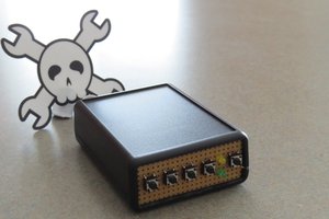
Hi and well done !
It does the job and that's the best kind of project. You may be intersted in a very similar (not mine) and taken further project :
http://cms.diodenring.de/electronic/microcontroller/82-intervalltimerv2