Close
0%
0%

Toast-R-Reflow

Yet another toaster oven -> reflow oven conversion

Similar projects worth following
Starting from
$60.00
nsayer has 2369 orders / 163reviews
Ships from United States of America
It seems like a rite of passage for makers that progress to surface mount work: building your own oven (or other appliance) to do reflow soldering.

When I arrived on the scene, I took a look at the available variations on the idea and found something in each of them that I thought was sub-optimal. A lot of folks use solid-state relays to switch the oven elements on and off. SSRs with sufficient capacity are quite expensive. By contrast, triacs are cheap and, while not quite as trivial as SSRs, they're quite easy to work with if you do just a little bit of extra designing. Other folks combined the logic components with the line voltage switching stuff. I knew that I'd be tinkering quite a bit, so I wanted to try and make sure that the high voltage stuff was at arms-length.

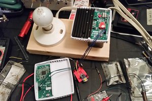
The Toast-R-Reflow design consists of a power board and a controller. When I started the project, I didn't actually have a reflow oven, so the power board was designed with through-hole parts. This has worked out fairly well. There aren't very many pieces to the power board, and there's little incentive to minimize its size.

Each channel of the power switcher is a basic opto-isolated triac circuit consisting of a MOC-3020 opto-isolated driver triac and a BTA-20 power triac.

In designing the power board, the biggest limitation was thermal constraints. I got the largest heat sinks that I could reasonably fit into the allotted space, but the thermal calculations must be quite conservative, since we're building it into an oven. Fortunately, the space behind the controls in the oven I selected (and this is likely true for most) stays relatively cool during operation. This is largely because the area is liberally ventilated, likely in an effort to insure that the user controls remain cool enough to be handled regardless of how hot the oven interior might get. Nevertheless, the operating specification for the power board is an ambient temperature of 50°C. Given the heat sink has a cooling capacity of 5°C per watt and the BTA-20's maximum operating temperature, its own junction-to-tab thermal resistance and the device power dissipation curve, what that winds up with is a maximum current rating of 8 amps. Since I'm in North America, the toaster ovens I use are 120 volts, so that 8 amps yields 960 watts. That's not quite enough, so I designed the power board with two channels. Since most toaster ovens have an even number of heating elements (either two or four - divided between the top and bottom) and they're usually controlled separately (so that the oven can support broiling), this works out just fine. The two channels can handle 16 amps total, which would probably be enough to start tripping circuit breakers if it were all used.

The input side of the MOC-3020s, like all opto-isolators, is merely an LED. Light the LED and the relevant heating element will turn on. But it's all-or-nothing: once a triac is turned on, it will stay on until the next AC zero-crossing. To get fractional power, you either need to do what a lot of lamp dimmers do and delay the triac turn-on during each cycle, or you need to do what every microwave oven does and just turn the elements on and off repeatedly to establish a fractional duty cycle. To do the former in software, you'd need to establish a zero-cross notification for the controller so that it could time the turn-on of the elements at least. To do it in hardware would require some sort of D/A conversion. The latter option is far, far simpler. As long as the time period for the PWM system is substantially longer than the AC cycle time, you can ignore the zero-crossings (in theory, it's still better to turn the triac on at zero volts, but in practice this has not proven to be necessary in my experience). I chose 1 second as the PWM interval. For 50% power, you turn the elements on for 500 msec and off for another 500.

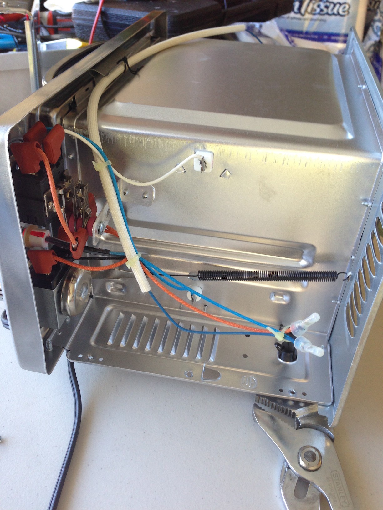
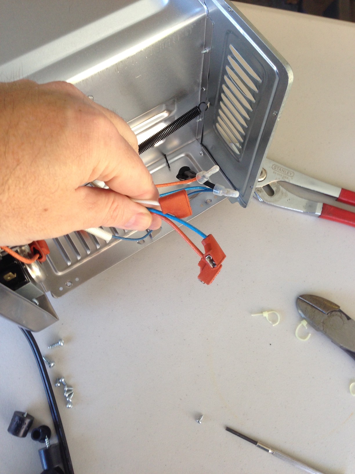
The power board has three board-mounted QD terminals. The oven I chose (and I expect quite a few of them do as well) used QD terminals for all of the chassis wiring. There were three of particular interest - one from the hot line of the incoming wire from the AC plug, and one from each of the top and bottom elements (in my case, the AC hot line QD terminal was the wrong size and needed to be replaced. I just used an ordinary crimp terminal from Home Depot). The three interesting QD terminals were attached to the matching terminals on the power board and the board was secured to the outer chassis with #4 bolts and 1/4" standoffs. When selecting a mounting location, make sure that nothing can come in contact with the board or wiring. Be particularly cautious mounting the board near ventilation holes - you don't want to be able to poke anything through the hole and touch the HV traces...

Read more »

Controller_84.pdf

Schematic for the ATTiny84 + AD8495 variant

Adobe Portable Document Format - 34.95 kB - 03/19/2017 at 04:22

Preview

Controller_84.sch

EAGLE schematic for the ATTiny84 + AD8495 variant

sch - 380.30 kB - 03/19/2017 at 04:18

Download

Controller_84.brd

EAGLE board file for the ATTiny84 + AD8495 variant

brd - 79.71 kB - 03/19/2017 at 04:18

Download

Controller_II.pdf

Schematic for the ATMega328 + MAX31855 variant

Adobe Portable Document Format - 39.45 kB - 03/19/2017 at 04:22

Preview

Controller_II.sch

EAGLE schematic for the ATMega328 + MAX31855 variant

sch - 422.20 kB - 03/19/2017 at 04:18

Download

View all 11 files

  • 1 × Toaster oven I used a Hamilton Beach 31138. What you're looking for in a toaster oven is the elusive combination of speed of heating with ease of disassembly
  • 1 × K type thermocouple http://www.sparkfun.com/products/251
  • 1 × 6-12 VDC @ 250 mA power supply with 2.1mm barrel connector, center positive
  • 1 × Toast-R-Reflow power board
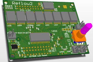
  • 1 × Toast-R-Reflow controller/display

View all 7 components

  • Power board design changes

    Nick Sayer05/18/2017 at 21:06 1 comment

    I went through the exercise of designing a new power board that includes a DC power supply. I'm not sure the result is worth doing, though.

    I added the footprint for a CUI VSK-S3 AC/DC module and changed the 3 pin screw terminal for a 4 pin one, with the 4th pin being the DC supply out for the controller. The trouble is that the board is now more than twice as large as it was, and the CUI power supply adds around $25 to the retail price - all to save you the trouble of just using a wall wart to power the controller separately.

  • Project updates

    Nick Sayer03/19/2017 at 04:41 0 comments

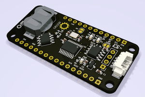
    I've added the latest EAGLE design files for the two controller variants, the power board and a new SMD variant of the power board.

    I'm still keeping the files around for a through-hole power board variant, as it solves the bootstrap problem. To build your very first reflow oven, you can use the through-hole power board, modify the oven, and then use an Arduino Uno and a thermocouple amplifier breakout board and jumpers as your first controller. Once you have that working, you can reflow an SMD controller and switch over to that.

    To make an Arduino Uno based reflow controller, buy an Uno, an AdaFruit i2c 2x16 LCD shield and an AdaFruit MAX31855 breakout board. SparkFun has a similar breakout board, but the AdaFruit one has a 3.3v LDO and level shifters so that it's 5v tolerant.

    Connect the breakout board ground to the Uno ground, Vin to 5V, !CS to D7, SCK to D13, DO to D12. Connect D2 and D3 to 150Ω resistors in series with the element lines for the oven. Connect a K thermocouple to the breakout board and route it somewhere convenient inside the oven.

    With that done, grab the i2c display version of the sketch from the GitHub repository. You will need the Arduino PID library and the LiquidTWI2 library to control the display. Upload that code into the Uno.

  • Design time for TRR version 2

    Nick Sayer07/06/2016 at 20:42 0 comments

    The inventory of boards is getting low, so it's time to consider feature-adds for the next generation of Toast-R-Reflow.

    The next version of the power board will be SMD. It's actually just a lot less effort for me to build the SMD portions of the board than to kit all of the through-hole parts. It will still be sold as a "quick kit" - the remaining through-hole parts (the triacs and their heat sinks, and the I/O block) will need to be assembled by the buyer.

    One other thing I'm considering is adding an AC-DC power module so that the toaster could supply the DC needs of the controller.

    I'm also considering changing the control method. With a DC supply on the board, I can change the control mechanism to be open-collector rather than the current 20 mA current mechanism (that is, lighting an LED).

    The AC-DC supply would, however, likely add $10 to the price of the power board, and perhaps knock a couple bucks off the price of the controller(s), as well as eliminating the need for a separate wall wart.

    I'd like design feedback. If anyone has any suggestions,

  • Please update your firmware

    Nick Sayer05/20/2015 at 03:48 3 comments

    If anyone reading this has a Toast-R-Reflow controller, please go get the latest firmware from Github.

    The change adds support for the AVR watchdog. The oven at The Hacker Dojo was discovered wedged somehow with one of the elements turned on. It's not immediately clear what happened, or if the watchdog would have prevented it, but the watchdog certainly can't prevent anything if it's not used.

View all 4 project logs

  • 1
    Step 1

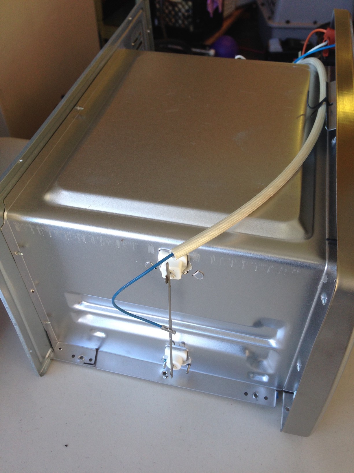
    First, take the oven apart enough to get to the internal wiring. What you want to wind up with is that the neutral line of the AC cord connects to one side of the elements. The hot line of the AC cord comes to a 1/4" QD female terminal, and the non-neutral-connected side of the two elements (or sets of elements) comes out to two other 1/4" QD female terminals.

  • 2
    Step 2

    Assemble the power board, then connect the incoming hot line from the AC cord to the HOT terminal, and then each of the two element lines to the OUT1 and OUT2 terminals. It doesn't matter which element connects to which terminal.

  • 3
    Step 3

    Drill four 1/8" holes in the outer sheet metal enclosure for mounting the power board. Select the mounting location carefully so that the heat sinks are as far away from the heat of the oven as possible, but still as well ventilated as possible, but also insure that you can't poke anything through any ventilation slots/holes that might touch the power board.

    Mount the power board using #4 bolts, nuts and 1/4" standoffs.

    Drill a hole sized for the cable grommet. Attach the three wires in the cable to the input terminal block on the power board. Route the cable out the hole and install the grommet.

View all 6 instructions

Enjoy this project?

Share

Discussions

Ricardo Ferro wrote 05/13/2017 at 14:17 point

Do you sell kits online?

  Are you sure? yes | no

Nick Sayer wrote 05/13/2017 at 14:25 point

Yes! See the Tindie store links of the project. 

  Are you sure? yes | no

Christoph wrote 01/20/2015 at 19:59 point

"What you're looking for in a toaster oven is the elusive combination of speed of heating with ease of disassembly" - well spoken. Have fun with your oven!

  Are you sure? yes | no

Nick Sayer wrote 01/20/2015 at 20:02 point

Thanks. This project was actually completed well over a year ago, and has been operating flawlessly. I'm just documenting it here.

  Are you sure? yes | no

Similar Projects

Does this project spark your interest?

Become a member to follow this project and never miss any updates