 Patrick
A large part of my graduate dissertation has me testing the flexural properties of brittle materials at a variety of conditions. I loosely follow a handful of standard and practices as I develop my test plans, and one thing that I have been concerned about what alignment of my testing fixtures and samples. All of the calculations I do assume that everything is perfectly parallel or perpendicular to each other, and when you have three objects you are trying to align, it gets difficult. This calls for a jig to help make sure I am the same every time I test. At least that way I will be consistent.
I test using a commercial, fully articulating 4 point flexural fixture and a home built 3 point one. It is fairly easy to align the top and bottom pieces of the 4 point fixture, but the added mobility and springs which make it articulating made it difficult to ensure the sample was well aligned. I had been shown by an expert how he used a note card with a notch cut out of it to tap the test sample into place, the same distance from the wall. The approach seemed solid, but lacked a little refinement.
A little 3D printed piece would let me push both sides together, ensuring that I truly ended up with a straight piece. I needed to equal width arms to push the sample, and a large flat piece to stop on the fixture. It also needed to be small enough to fit between the bottom rollers where the sample was. While the 4 point jig works well, the next iteration I need to include a better handle or grip to help me navigate the springs on the fixture.
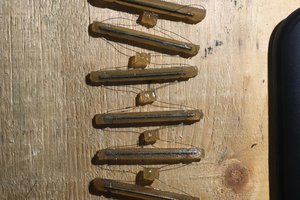
On the 3 point fixture, my concern is aligning the top and bottom pieces correctly. The test area is at the end of two 18 inch rods, which run though a steel chamber and furnace, leaving a lot of wiggle room when setting things up. I initially designed a piece with square wells that sat over the rollers, but there ended up being more wiggle room than I desired. In the next iteration I decided to use circular wells to let the rollers naturally rest and align themselves as the top piece came down, pushing everything into alignment. Once it is all aligned, I can tighten the various bolts and screws to hold it in place. The size and shape of the wells could use a bit more refinement. If I need a next version, I will probably keep the depth of the well, but make them shallower, as to further reduce tolerances when aligning.
Because all of the parts were fairly simple in design, I used Tinkercad to build them. Both the STL files and links to the Tinkercad projects are provided.
 David Matthew Mooney
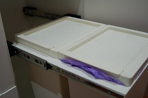
 Myles Eftos
 Nixie
Nixie