0%
0%
Keplermatik
Vintage U.S. and Soviet Hardware come together in a Mission Control-style console that actually tracks satellites.
Become a Hackaday.io member
Already have an account? Log in.
Just one more thing
To make the experience fit your profile, pick a username and tell us what interests you.
Pick an awesome username
hackaday.io/
Your profile's URL: hackaday.io/username. Max 25 alphanumeric characters.
Pick a few interests
Projects that share your interests
People that share your interests


 Samuel A. Falvo II
 Jorj Bauer
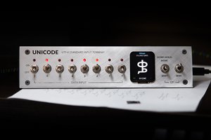
 Stephen Holdaway