-
PCB:s arrived
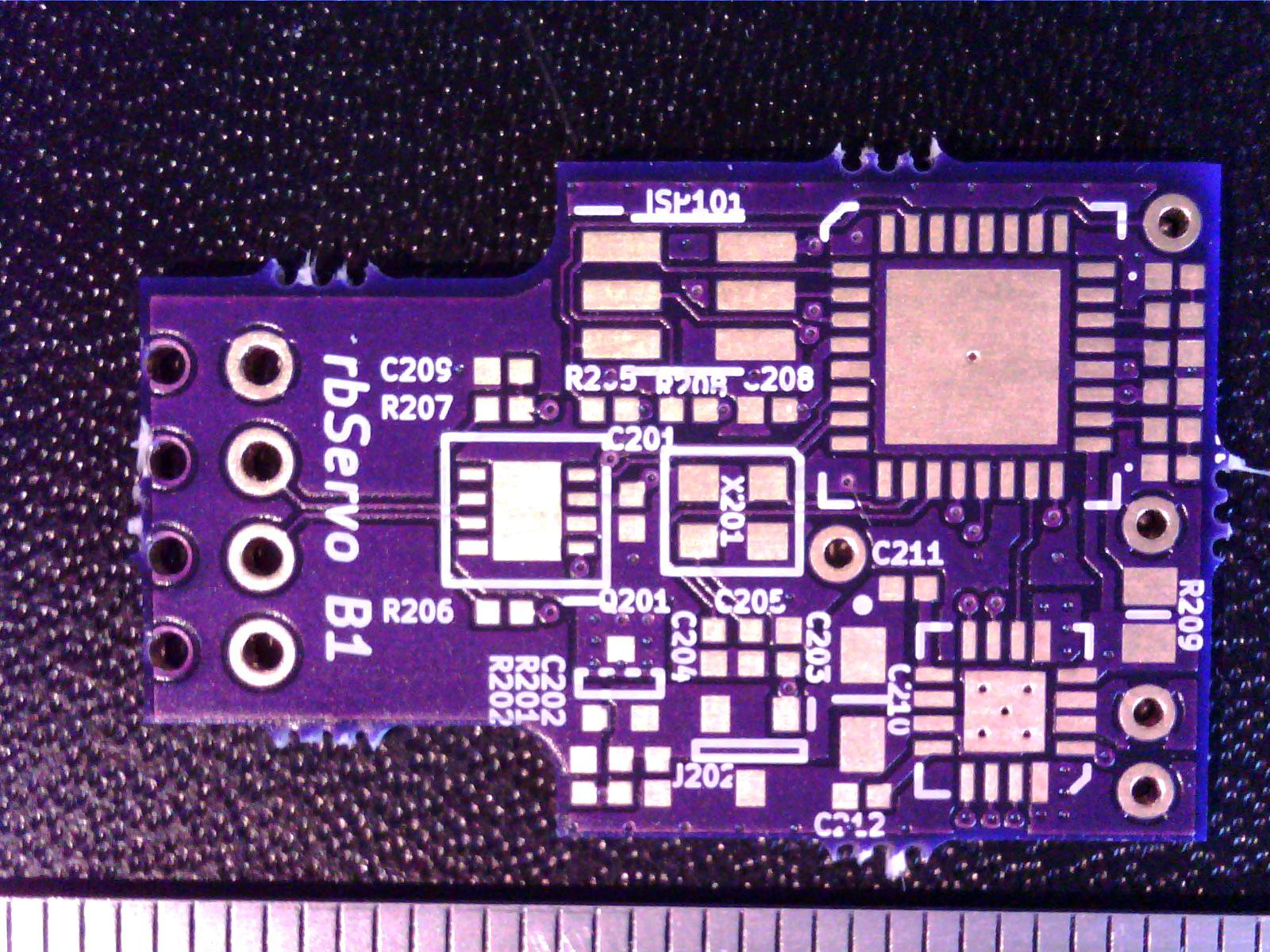
04/09/2014 at 20:22 • 0 commentsWhen I got home from work, a familiar purple envelope was waiting for me. I fired up my microscope and inspected the PCB:s straight away. This is the first time I have ordered 4-layer PCB:s from OSHpark.com, and I was anxious to see how they turned out. Notice how the copper pour is not centered in the board? The alignment is OK in the left/right direction, and a bit worse in the up/down direction. We can rule out a problem with the Gerber files by looking at how far into the board the "mouse bites" extend. At the top and bottom edges, the drilled hole edges extends past or does not reach the board outline respectively, indicating that the drilling and routing stages could be aligned better. The mouse bites are drilled together with all the other holes (before plating and etching), but the outline is routed as the very last stage in production. I could not get a good photo of if, but if I look directly at the bottom edge, I can see the stitching vias through the fiberglass. When I sanded the remains of the mouse bite away, the sand paper bit into them, exposing copper.
This small misalignment is not a problem for me, just something I need to remember to take into account for the next revision.
I'll check with OSHpark if I should expect better in the future. ![]()
The outer dimensions are 0.1 mm larger than nominal, but that is well within tolerances and the board fits exactly as it is supposed to! ![]() Other than the outline alignment issue, the board is stunningly beautiful! The purple solder mask on this board is less glossy compared to the 2-layer boards I have bought previously, and it looks a bit more refined. The soldermask alignment is perfect, and the silkscreen is easily on par with boards that cost ten times as much! The drill alignment is also very good.
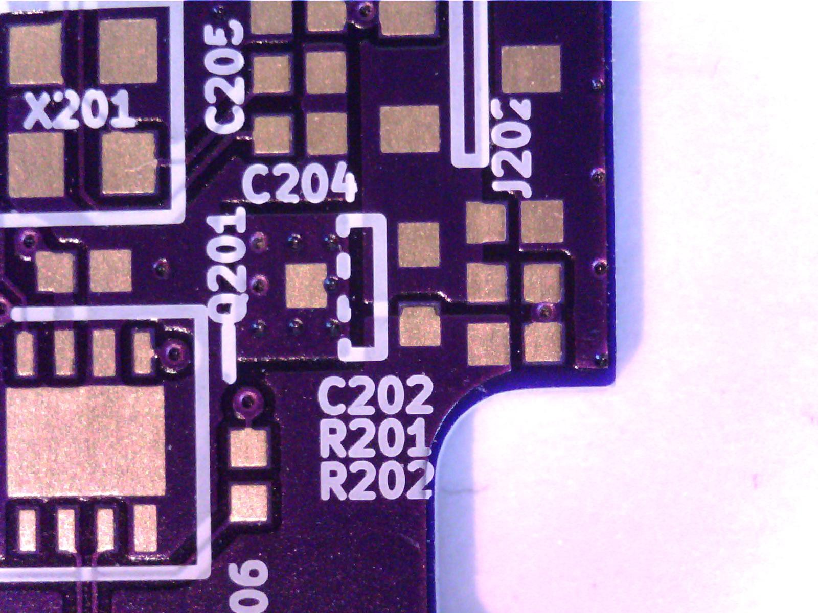
Other than the outline alignment issue, the board is stunningly beautiful! The purple solder mask on this board is less glossy compared to the 2-layer boards I have bought previously, and it looks a bit more refined. The soldermask alignment is perfect, and the silkscreen is easily on par with boards that cost ten times as much! The drill alignment is also very good.In the image below, the component designators are approx. 0.65 mm high, and the text is still razor sharp and extremely easy to read. Really, really good looking! The breaks at some points are due to collisions with vias, and not a problem with the printing. If you look at the curve of the copper pour, you can see that it does not follow the board edge evenly. This is also due to the slight misalignment. ![]()
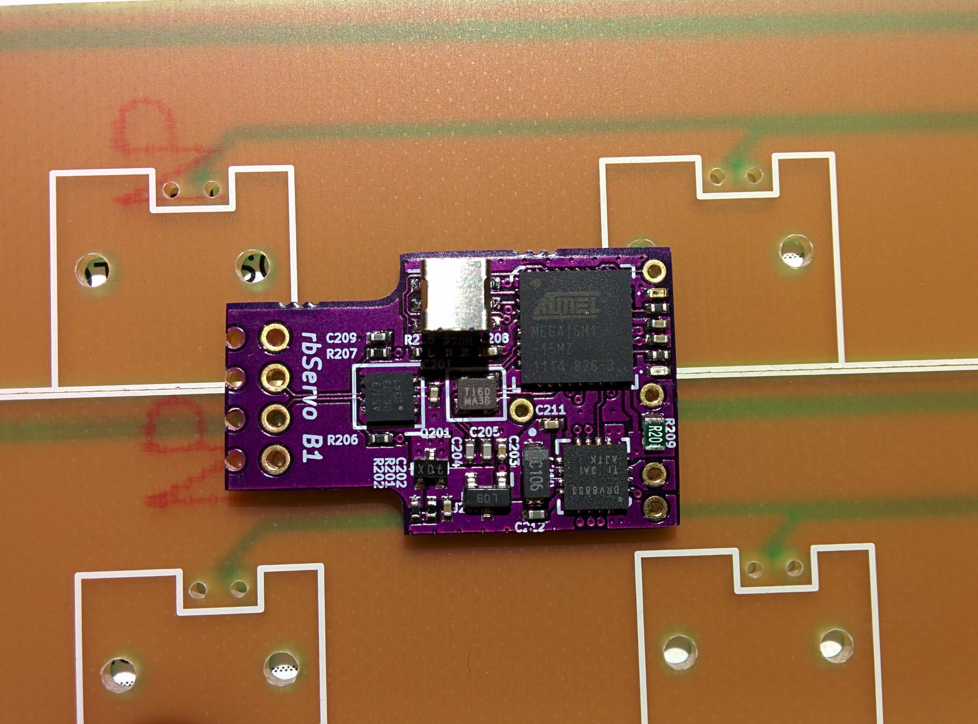
After solder paste printing, component placement and hot air reflow the board came out looking like this:
![]()
I used a solder stencil from OSHstencils.com this time, and it worked really well. I could not see that it was in any way worse than the stencils I have ordered from ohararp.com, but they were a lot cheaper!
The corners are a bit rounded in this pic, I need to be more careful when sanding the mouse bites away.
The next step is to try them out, but that is for another update.
-
Servo lid arrived
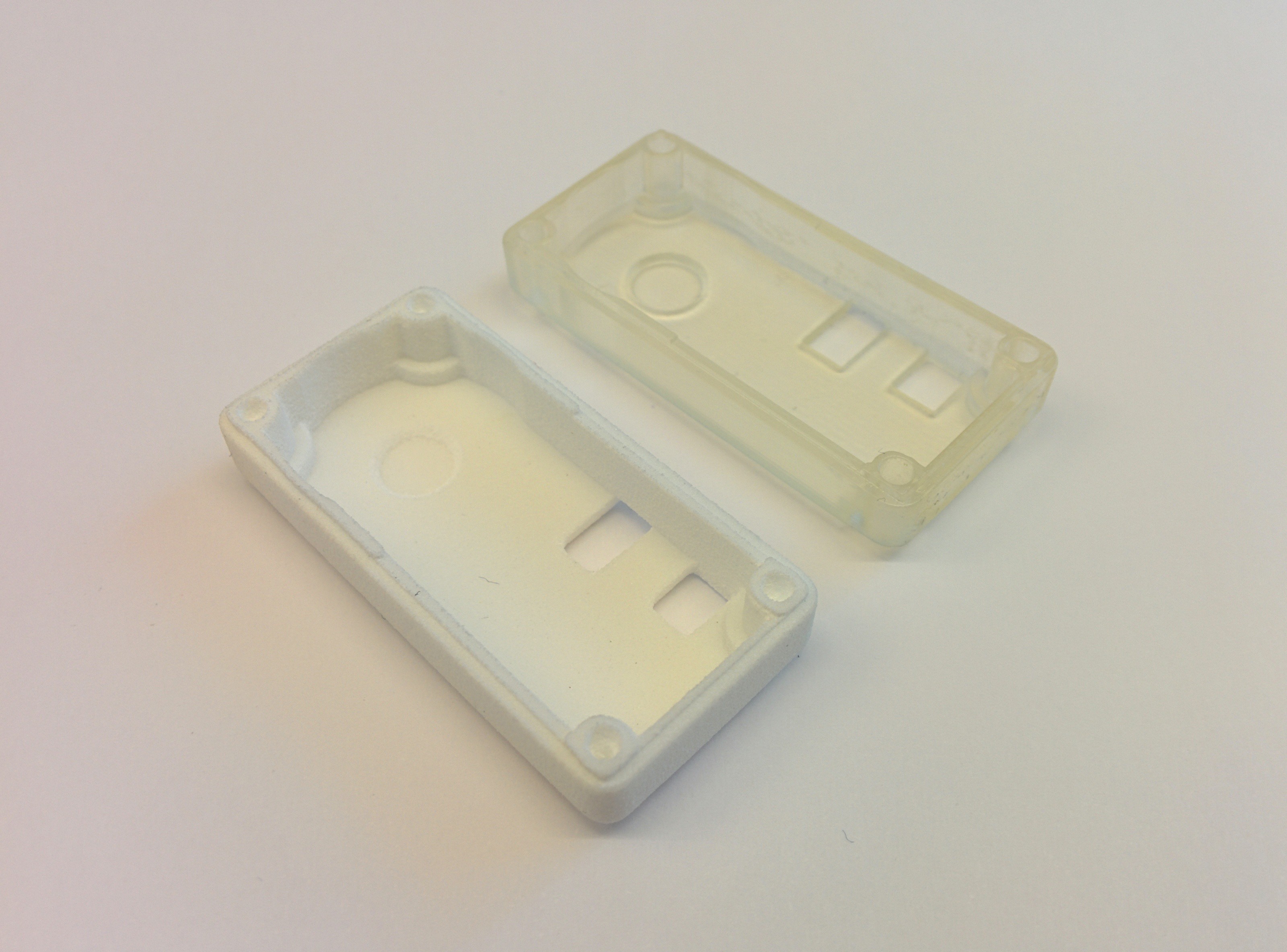
04/02/2014 at 18:37 • 0 commentsShapeways delivered my 3D printed servo lids today. I ordered two, one in the cheapest material available, and one in the "Frosted ultra detail" (FUD) material.
![]()
![]()
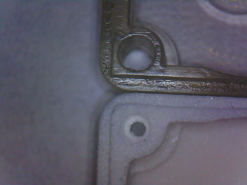
Everything is sharper on the FUD version - the edges are cleaner and the holes does not need to be drilled out. The dimensions are very similar though, and they both fit equally well on the servo body. The FUD material looks cooler though :) I'll make a few small adjustments to improve the fit even further.
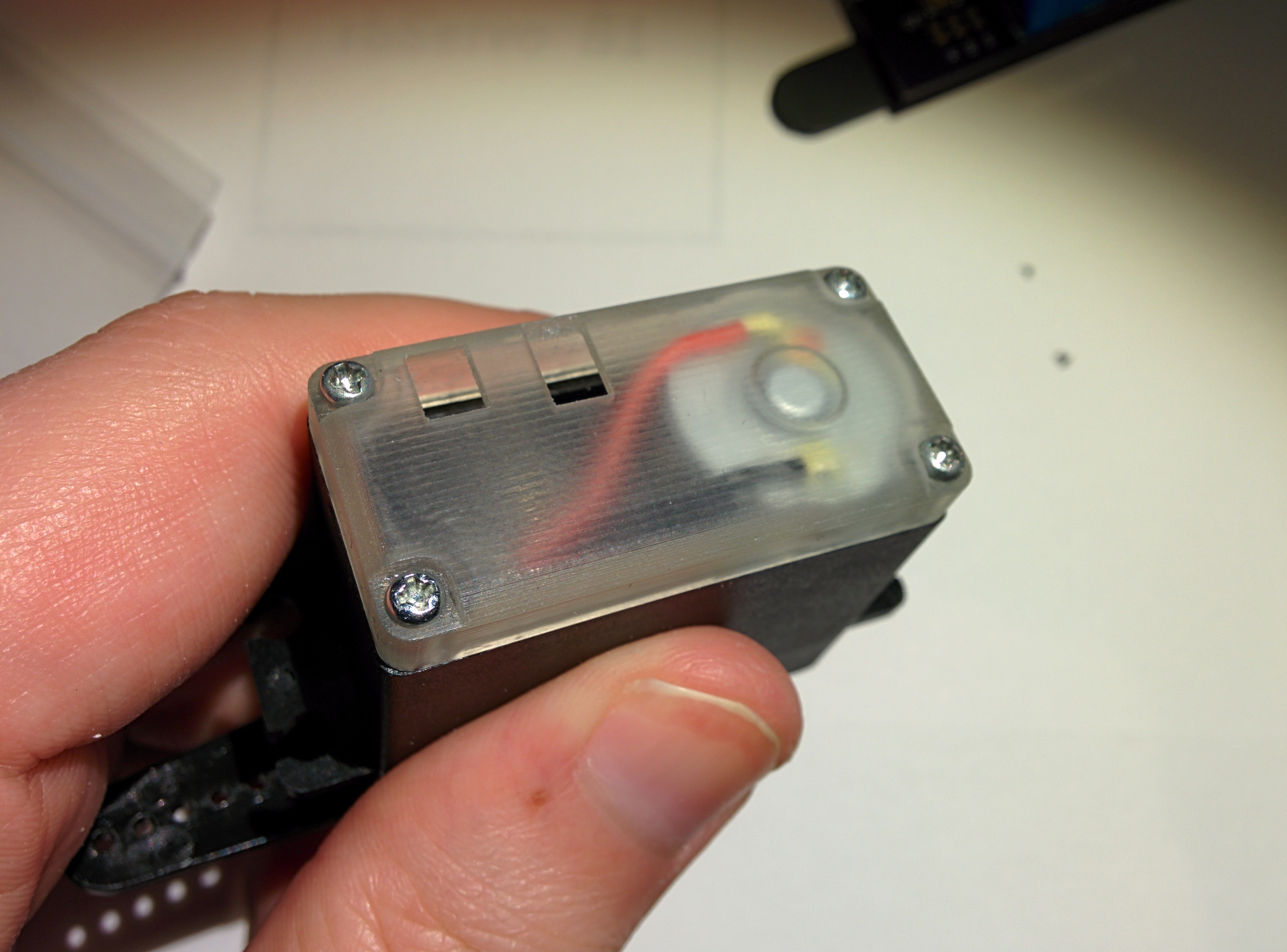
![]() I got all the components I need last week, so now I'm just waiting for my PCB:s and my solder paste stencil. The cutout in the lid is for the debugger adapter, let's hope everything lines up.
I got all the components I need last week, so now I'm just waiting for my PCB:s and my solder paste stencil. The cutout in the lid is for the debugger adapter, let's hope everything lines up. -
Hardware changes between rev. A and B
03/23/2014 at 18:45 • 0 commentsWhile Rev. A was a success when it came to get CAN traffic working and starting to learn how the ATmega16M1 works, some changes were needed for Rev B.
1) PWM motor control is moved from the PSC (Power Stage Controller) to the PWM generator on TIMER1. This might seem strange since the PSC is explicitly designed for motor control applications. However, before I built Rev A i didn't notice that the PSC is only available on the more expensive ATmega16M1 and ATmega64M1. In an effort to keep costs down, I opted not to lock myself into the more expensive option.
2) I dropped all plans of running an external magnetic encoder over SPI. I had built a 12-bit resolution magnetic encoder, but was having trouble with the mechanical properties. The alignment of the magnet and the sensor chip was extremely sensitive, and I never got it working properly. As a result, the movement range is now limited to the approx. 200 degrees of the unmodified servo instead of the continuous rotation I had planned originally. Also, adding a sensor, magnet and custom shaft to each servo would be pretty expensive.
3) A second LED is added for more useful feedback
4) I had made a mistake by connecting ARef to 5V. This makes it impossible to switch between the different voltage references available to the AD converter, and even trying might damage the chip. Also it makes measuring the internal temperature of the chip impossible.
5) The CAN transceiver was replaced to a model with similar characteristics, but which was available in a smaller package.
The first batch of Rev B PCB:s will be manufactured during next week, and they'll take another two weeks to arrive in my mailbox. During that time, I hope that I'll also get all the components needed as well as the 3D-printed servo lids. I'm expecting the PCB for my debugging adapter during next week as well, without that I can't get my firmware on the chip. A CAN bootloader is planned for the future, but I haven't made any progress on that yet.
-
3D-printed servo lid
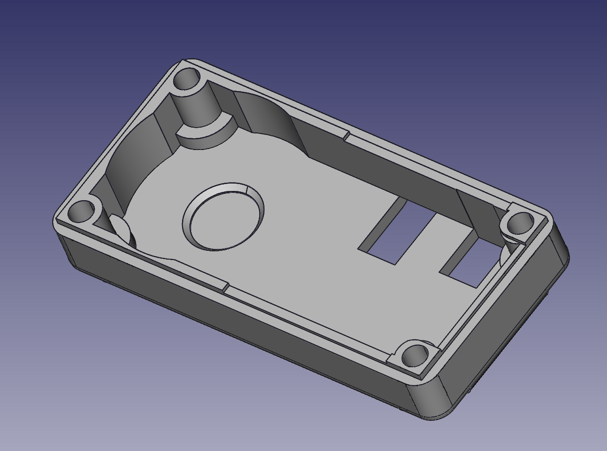
03/23/2014 at 13:16 • 0 commentsThis is the new lid that I have designed for the servo.
![]()
Why a new lid? There are two reasons:
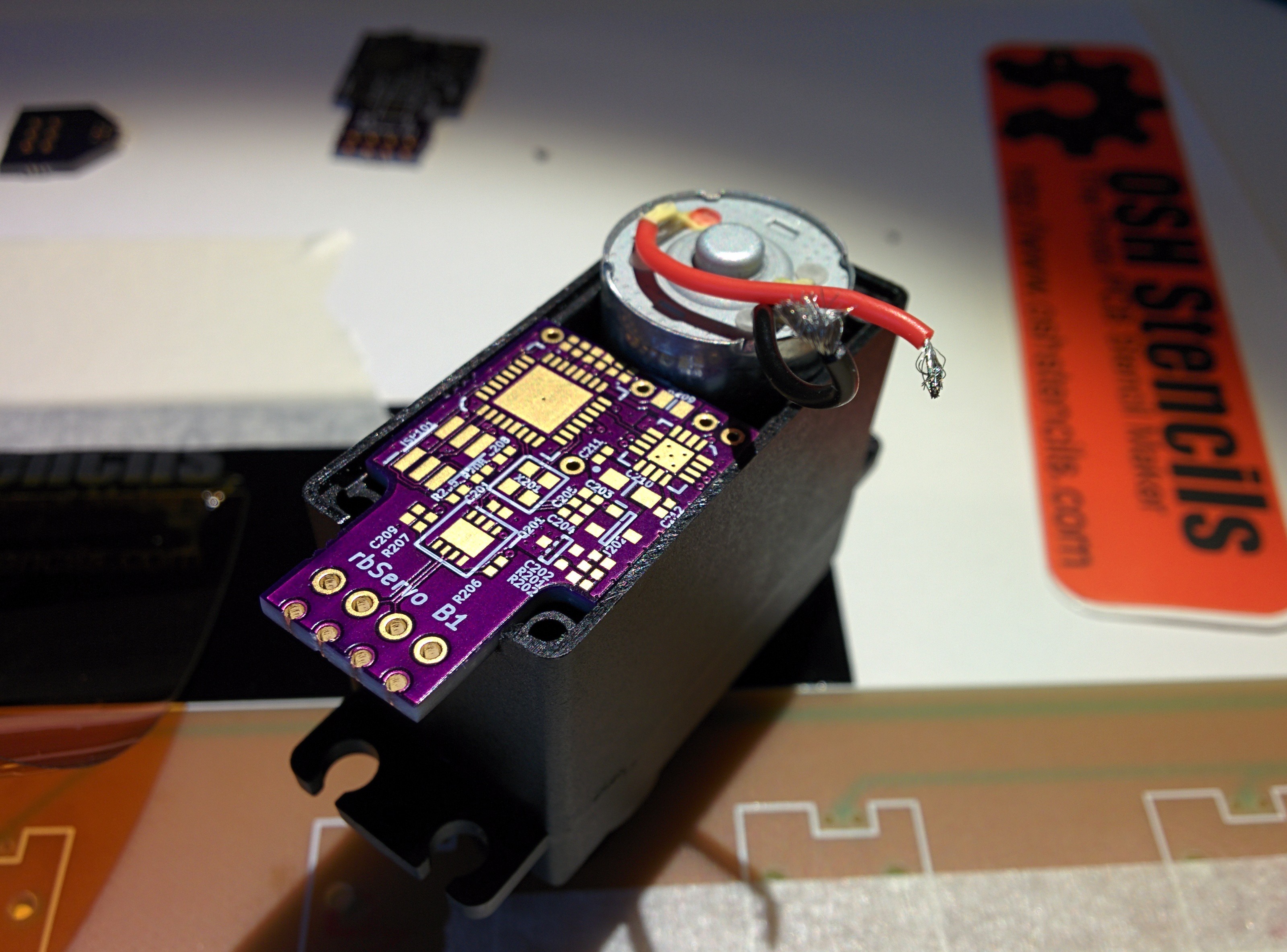
1) The new PCB is thicker than the original. If I didn't modify the inner lip, it would interfere with the circuit board and I wouldn't be able to get the lid seated properly. You can see the cutout on the right side of the servo. It's only .35mm deep, but that small cutout makes the difference between a proper fit and a crooked lid. The servo is ultimately held together by the four screws in the corners, going into the top of the servo. If the lid is not in its proper place, the top of the servo can move which is bad.
2) I need to be able to debug the software even when the servo is installed. The smaller cutout to the right is for the debugger port itself (a 1.27 mm pitch SMT receptacle), and the larger one to the left is necessary because of pins protruding from my debugger adapter board. Not pretty, and I will remove the second cutout for the next revision. I'll also update the another ISP adapter so that it is not as cramped.
So I'm ordering this from shapeways, and I'll update with pictures of the real deal when I get it.
-
Introduction
03/22/2014 at 23:01 • 0 commentsI have been thinking about this project for some time. It all began with a video on Youtube of a hexapod robot:
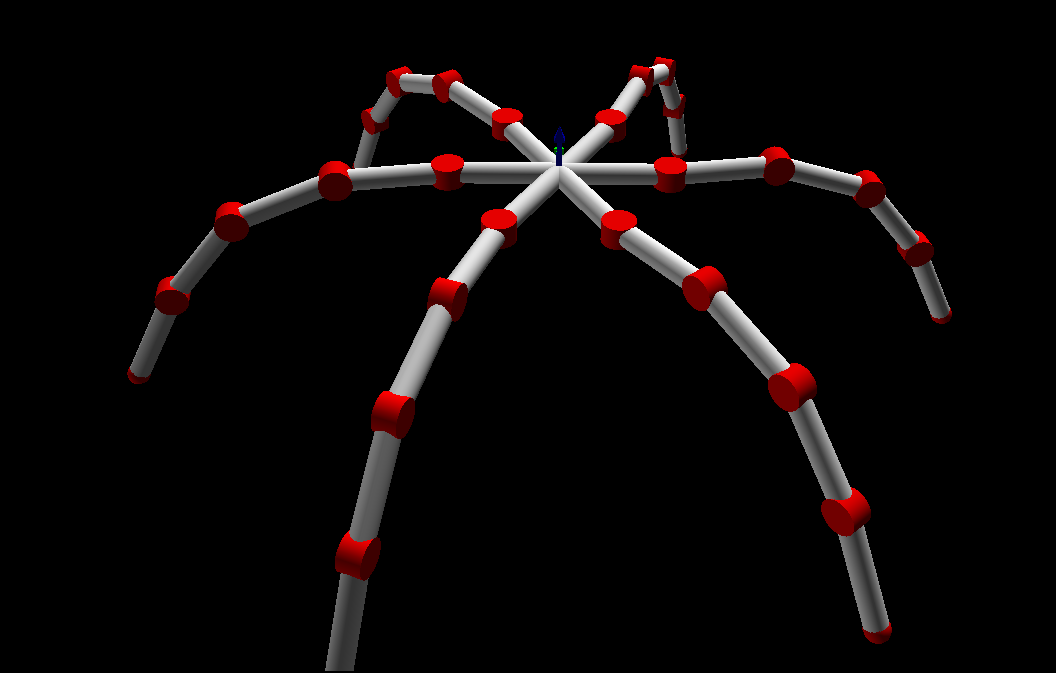
I was really impressed with the fluidity of the motions, and started reading up on motion control. I experimented with Inverse Kinematics, and designed a crude simulation in Python of a hexapod of my own. This had 4DOF per leg, and I got it working to some extent. The image below shows my (ugly) model. It is as simple as can be, the red cylinders represents the joints while also visualizing the axis. The gray cylinders represents a stiff connection between the joints. While this model does not take gravity, material stiffness or anything like that into account, it was a great tool to learn about the difficulties to calculate servo motion. I also started thinking about how to actually build it. ![]() At this point (fed up with programming) I decided that I should look into improving the servo controller usually found in a standard RC servo. Not because it was entirely necessary, but because it seemed fun. I found a few open-source alternatives, but they all ended up being unsuitable in one way or another. So I set out to build my own.
At this point (fed up with programming) I decided that I should look into improving the servo controller usually found in a standard RC servo. Not because it was entirely necessary, but because it seemed fun. I found a few open-source alternatives, but they all ended up being unsuitable in one way or another. So I set out to build my own.I decided that the servo should communicate through a CAN bus.
It is very robust, and handles multiple nodes in a very elegant way. It can be thought of as a real-time database of information that all nodes have access to - any node can send information at any time, and all nodes can see it. Messages are automatically prioritized, and collisions are handled according to message priority. It really is well thought out, check out the Wikipedia article! After a lot of experimentation and frustration with Arduino and a few MCP2515-based CAN shields, I decided that I should go for a microcontroller with a built-in CAN controller instead. The size requirements also dictated this - if it was going to fit inside a RC servo, I won't have room for both a microcontoller and a CAN controller. The choice fell on the ATmega16M1 - basically an ATmega328P with CAN and a dedicated motor controller, but half the amount of flash/RAM. If necessary, I can easily upgrade to the pin compatible ATmega32M1, or its big brother ATmega64M1.
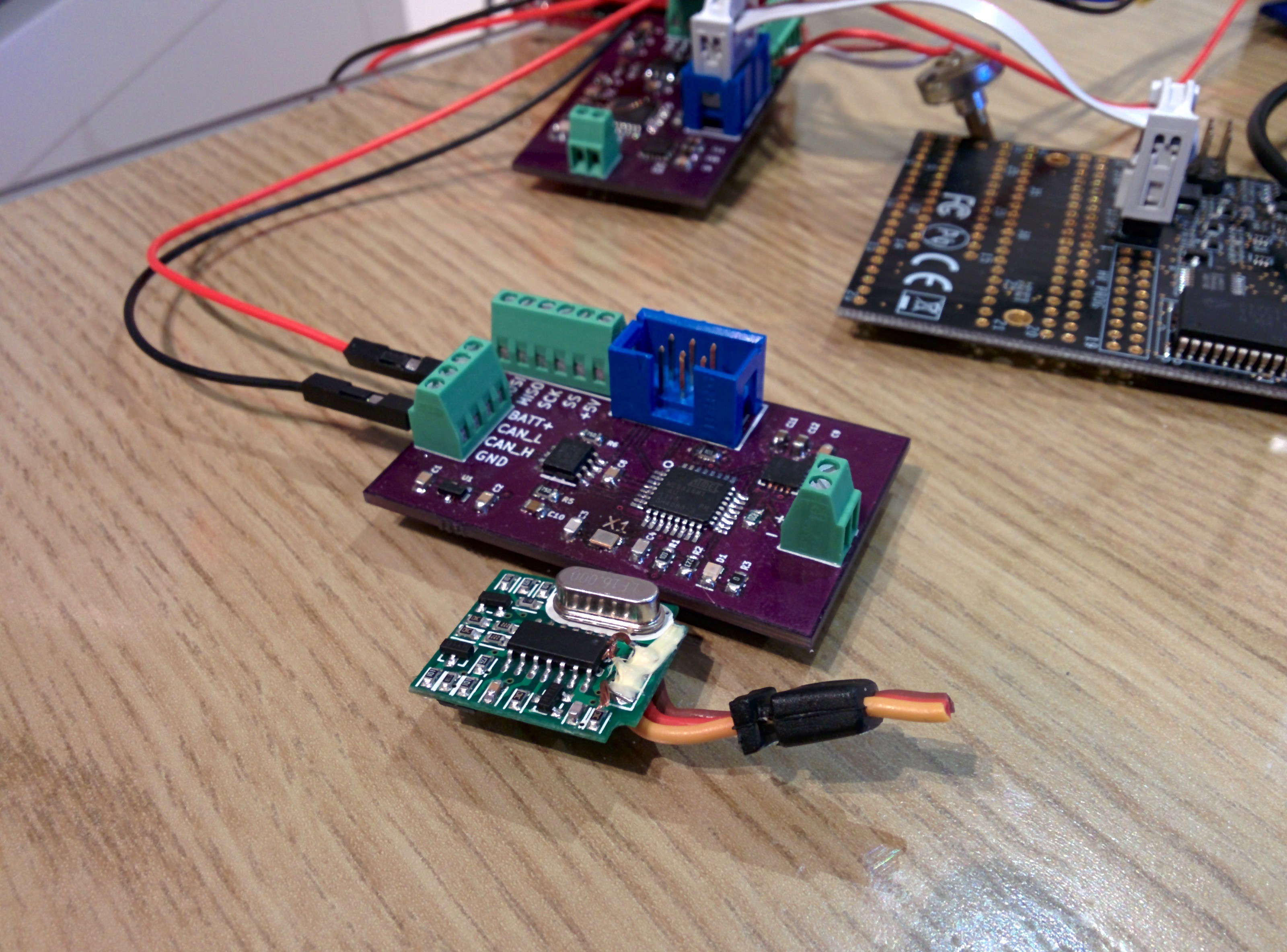
This is my first prototype (the purple board) compared to the original servo controller. The next revision will have shrunken my design down to an even smaller footprint than the original.
![]() This prototype was build to to a basic concept test - especially of the CAN communication. After being completely fed up with trying to build some kind of USB - Arduino - MCP2515 - CAN adapter, I built CANPi.
This prototype was build to to a basic concept test - especially of the CAN communication. After being completely fed up with trying to build some kind of USB - Arduino - MCP2515 - CAN adapter, I built CANPi. This proved to be a much better tool to get the CAN traffic running as it should, and finally I felt confident enough to start working on Rev B, which is what the next post will be about... Stay tuned!
 RasmusB
 Other than the outline alignment issue, the board is stunningly beautiful! The purple solder mask on this board is less glossy compared to the 2-layer boards I have bought previously, and it looks a bit more refined. The soldermask alignment is perfect, and the silkscreen is easily on par with boards that cost ten times as much! The drill alignment is also very good.
 I got all the components I need last week, so now I'm just waiting for my PCB:s and my solder paste stencil. The cutout in the lid is for the debugger adapter, let's hope everything lines up.
 This prototype was build to to a basic concept test - especially of the CAN communication. After being completely fed up with trying to build some kind of USB - Arduino - MCP2515 - CAN adapter, I built