Nixie 'Display of Things'
Use a combination of six Nixie tubes with a 16x2 LCD display and Pi2 with Adafruit Proto-Perma HAT to display information.
Use a combination of six Nixie tubes with a 16x2 LCD display and Pi2 with Adafruit Proto-Perma HAT to display information.
To make the experience fit your profile, pick a username and tell us what interests you.
We found and based on your interests.
I've done almost all the prototyping and testing I think is possible to ensure everything will work well together, so I have turned my attention to getting the circuit design laid out on Stripboard. I've never settled on a particular electronics design package for my circuits, and have never done enough to warrant investing much money into purchasing one either. I recently used a free application called 'VeroDes', but this was basic and relatively old. For this project, I have turned to trying out 'Fritzing', and I must say it is a pretty good application. There are four views on the designer, laid out in the order you might be expected to progress your project. It starts with a 'Welcome' tab [for those who might need a guidance on how to get going], a 'Breadboard' tab [for those who have done this stage of prototype, and want to copy it into Fritzing], a 'Schematic' tab, a 'PCB' tab [where you can arrange your component connections and have Fritizing attempt to Autoroute], and finally there is even a 'Code' tab where you can write your code and directly upload to your Arduino or Picaxe from within Fritzing.
I mocked up the Adafruit Perma-Proto Pi HAT in the Breadboard Editor using the Stripboard object, and quickly realised I would be able to fit far less on this board than I had originally though. I did suspect I'd have to stack at least one more board on top, but it seems this will need more stacking.
As it turns out, the stacked boards are nicely separated out into specific roles. At the bottom of the pile there is the Perma-Proto HAT, which contains the K155ID1 driver chip. The top header carries 5v, GND, 3v3 and GPIO signals. The bottom two headers carry cathode pins 0...9 in the correct order.
On the next level, there's the high-voltage transistors for multiplexing the Nixies and the Neons. The additional header at this level [bottom left], provides a 170v line to the high-voltage transistors, and seven multiplexed anode power outputs.
Finally, at the top level there is the power handling. The 12v & 5v PSU feeds the Pi and the HV module from here. Note: Think think I can see errors in this one, which I did fairly late last night - no surprise there are mistakes! Will be verifying connectivity on all htese board, both in Fritzing and physically! This board has an additional female header at the top left, which is where the HV module will plug in. There is also a male heade in the centre of the board, which will connect to the 12v & 5v PSU.
There is also the Display Board where the Neons and the Nixies live. I'll either use a Ribbon Cable, or just a bundle of wires to interconnect the Driver Stack to the Display Board. Not decided on which option yet.
Note that the HV Module, 12v & 5v PSU, and the Nixie Boards are not shown in these pictures, but will plug into the headers that are on the Stripboards.
It's time to bite the bullet and proceed with the critical stage in this project: Interfacing the Raspberry Pi's 3.3v logic with the 170v power supply in order to officially drive a few of the Nixie Tubes for the first time in this project. First step is wiring up some power for the HV Module and the Pi, and giving it a test with the multimeter. For this I am using my usual 12v PSU and stepping down to 5v using the BP5275-50.
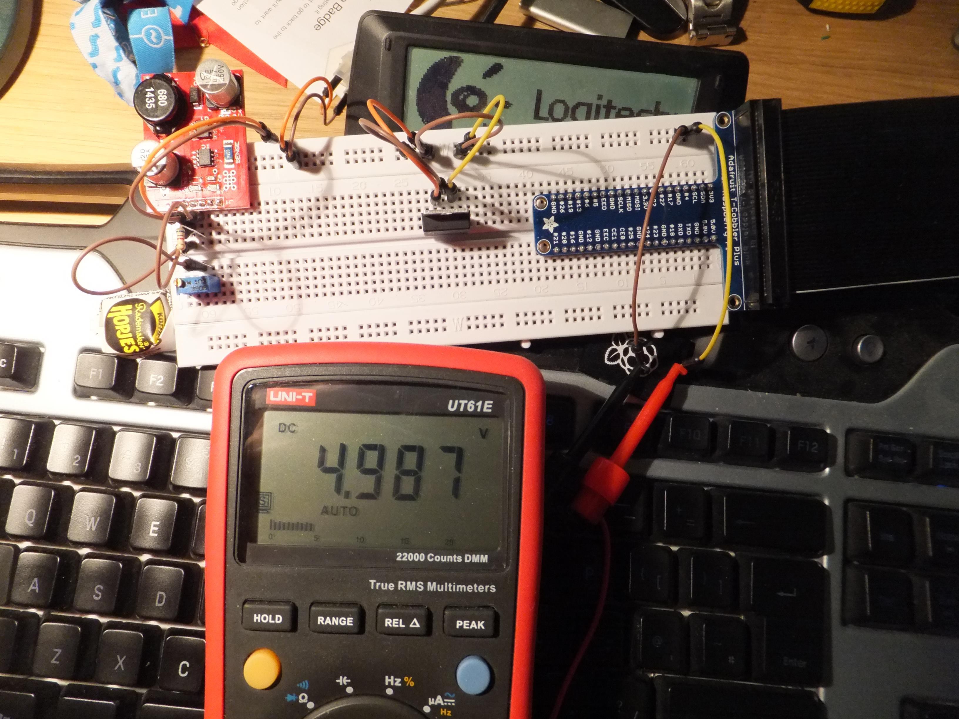
Might as well get on with trying the 5v supply to the Raspberry Pi...
After a bit of head-scratching over positioning of the components on the breadboard, I managed to get enough wired in to test four Nixies.
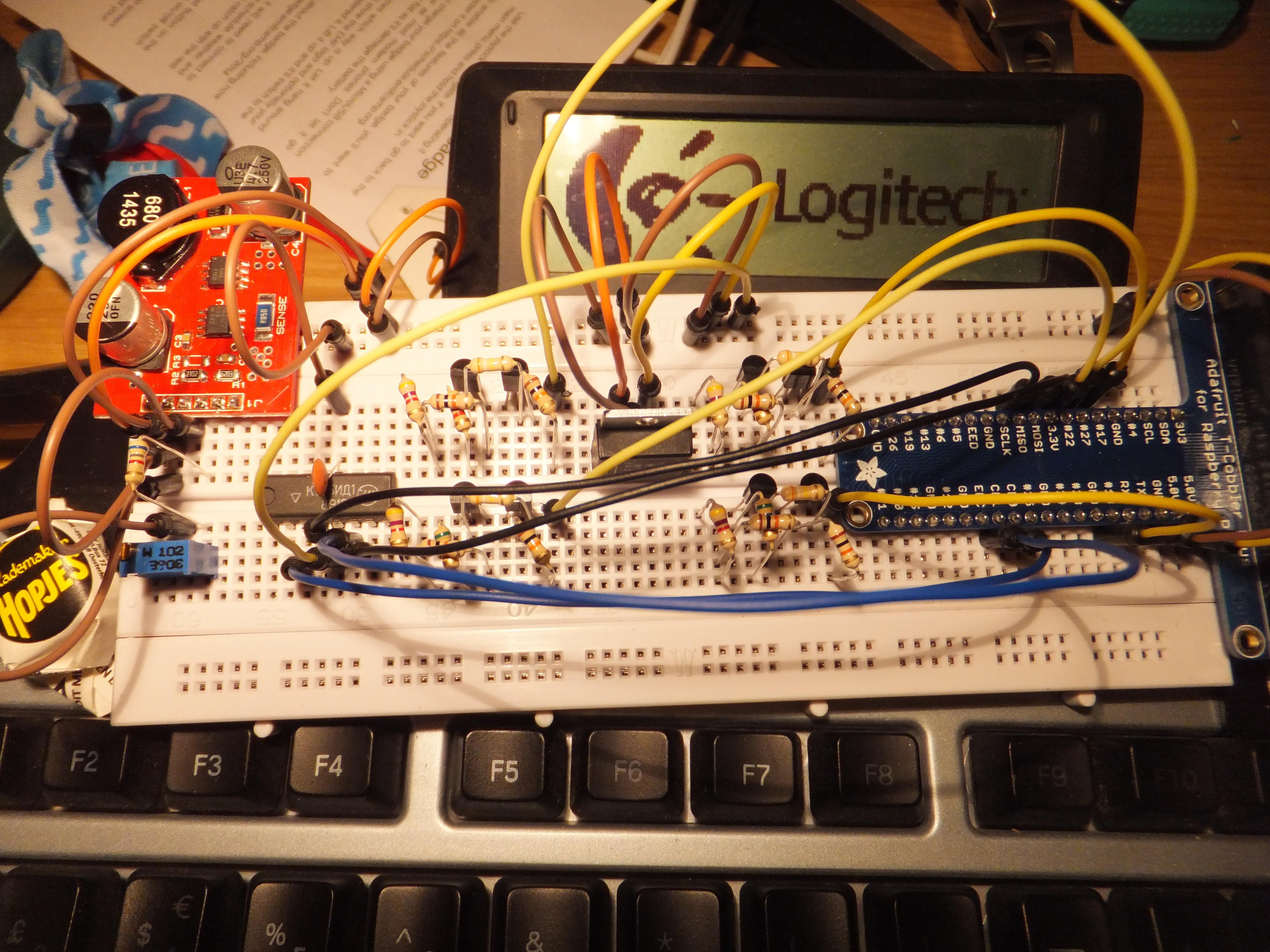
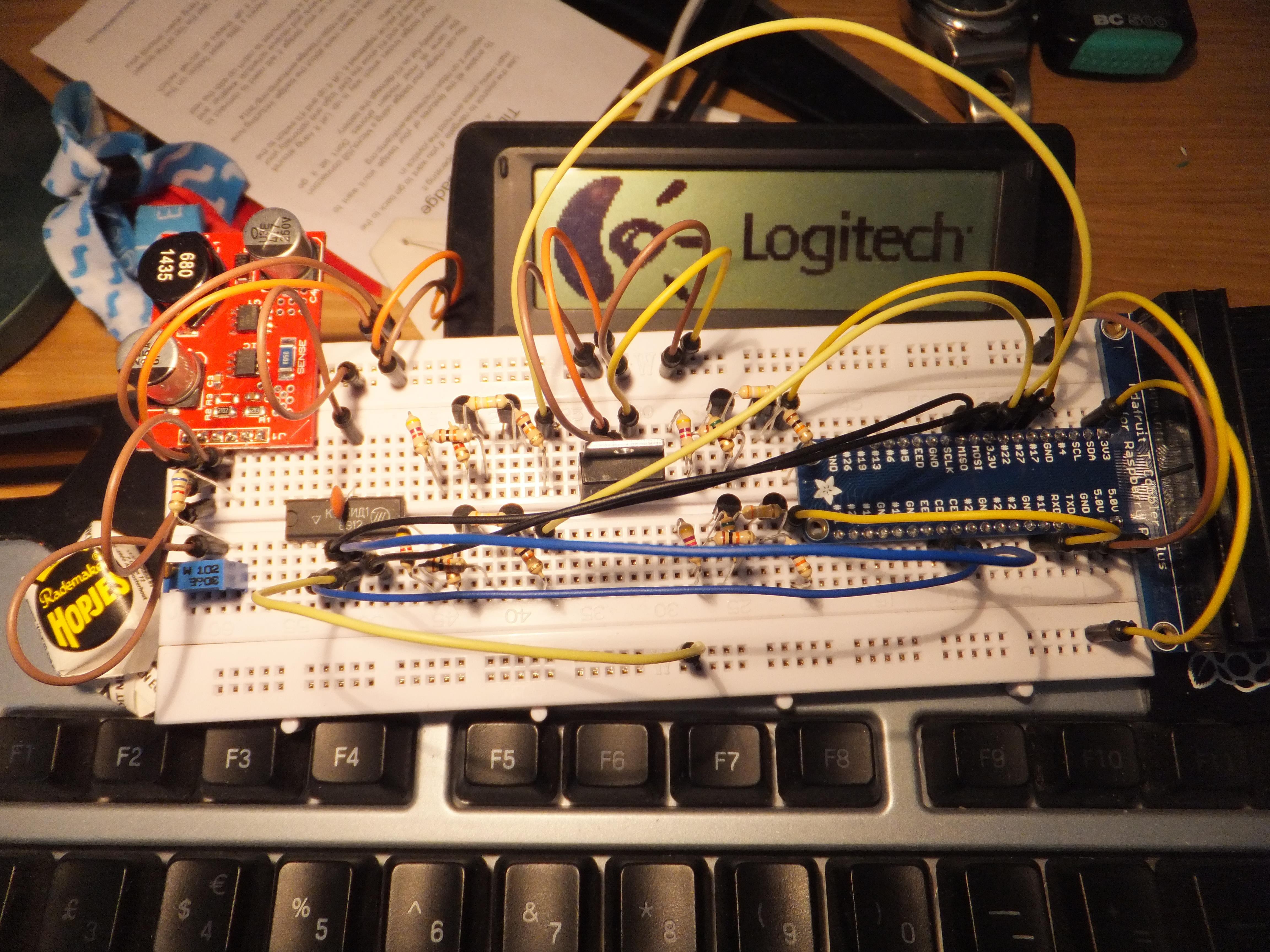
I had already video'd a test of the Pi and the K155ID1 with the incorrect 5v link to Vcc, but all seemed to go OK - no magic worky smoke escaping yet!
Update: 7th June 2015
Since the last update, I've added in the rest of the jumper wires along with a Nixie Tube, powered up the test circuit and ran the Raspberry Pi code.
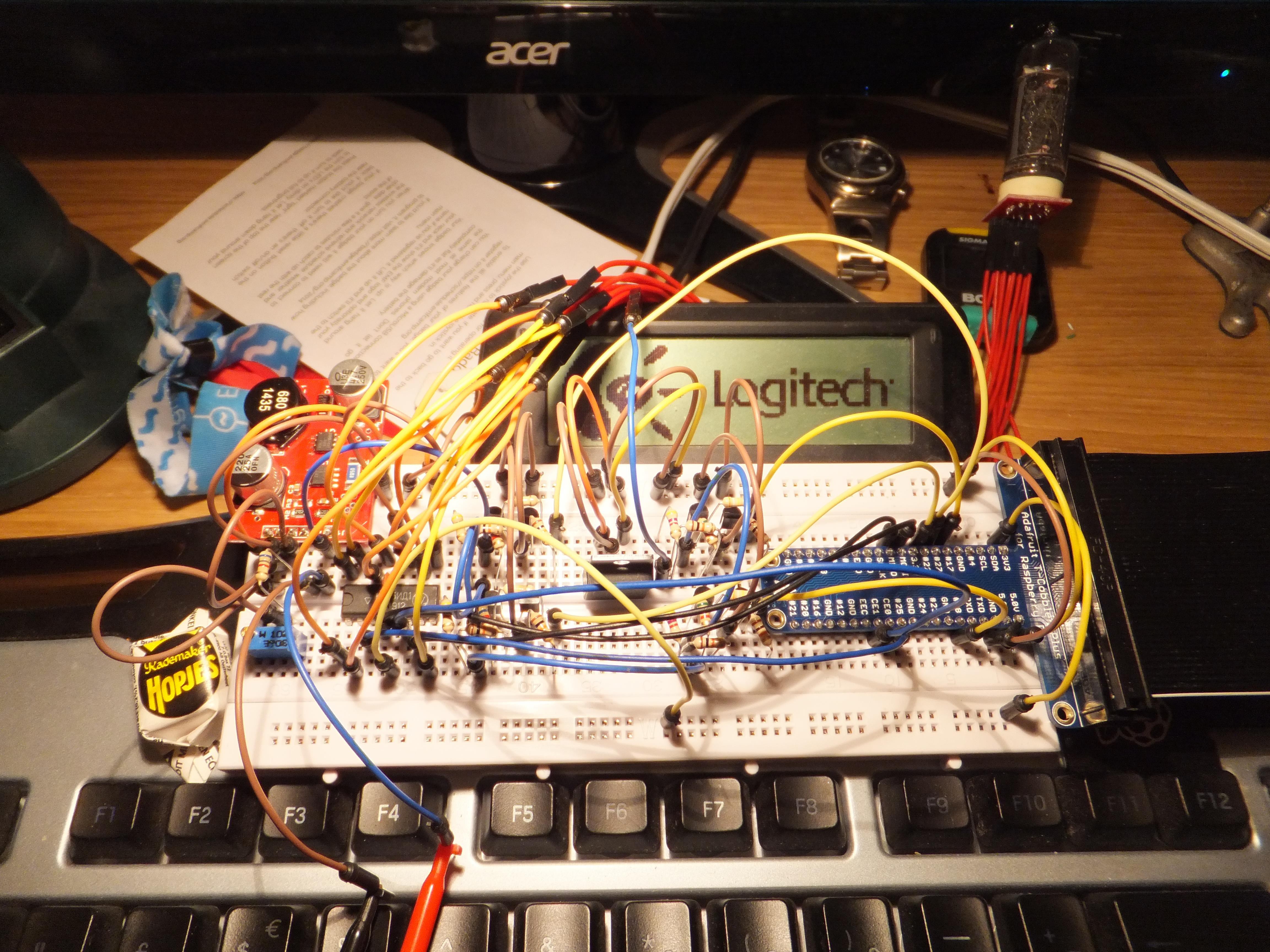
In short, the test was a success in that nothing blew up, but I did notice that I'd wired the BCD pins on the K155ID1 in the order of LSB (Least Significant Bit), but had coded the software in the order of MSB (Most Significant Bit). Easy enough to fix in either software or hardware.
Thought it would be nice to do a quick video of the Library running with some console debug output, and corresponding GPIO operation with some LEDs. Please note that I have deliberately slowed down the refresh rate so I can see that the GPIO polling is working correctly.
I've hidden away and burned the midnight oil to finish off a Nixie Tube Driver Library of which I am satisfied. As previously mentioned in Testing the Nixie Tube Library, I've ended up with three classes that make up the Library Model. These are named 'NixieTube', 'NixieDriver' and 'NixieDisplay'. I've hopefully written this well enough to be worthy of the 'Model-View-Control' concept.

I've written enough in each class [for now] to make it usable in this specific application, but there are so many more functions I could write to make the Library more complete and flexible. the NixieTube and NixieDriver classes both have 'runBlock()' functions and 'callback()' function pointers.
The reason for the name of this function is that it must be called as often as possible during the lifetime of the program, and when it is called it will 'block' [sleep] the thread one or more times, for timing of various actions. It updates the state of the object(s), so in the case of the NixieTube it will set the tube state to 'on', wait a while and then set the tube state 'off'. I had originally planned to avoid using a 'blocking' [sleep-calling] in favour of 'non-blocking' [without sleeping] where I would have stored an offset to the next time a particular action needed to happen, and used if-statements to keep track of the schedule. This turned out to be CPU-hogging (100% on a CPU core), power-hungry and does not play nice on a threaded OS like Linux. I'm too used to Micro-controllers, it seems! The alternative 'blocking' method, on the other hand, typically uses 3.5% of a CPU core. Far more efficient and friendly.
This Drivier Library is specifically a 'Model' and does not care about the 'View' or 'Control' detail. All the Model does is indicate that an action has taken place, and that is partly where the 'callback()' function pointers come into play. The 'callback()' function pattern in my implementation is Asynchronous, so it also serves as an Event Handler. For my tests (and possibly my final version in this project), I'm assigning only one function via the NixieDriver's setOnCallback() and setOffCallback() setter functions. This is more than enough for what I need to do right now, and could be optimised slightly by calling a separate function for 'on' and 'off' to save unnecessarily polling certain GPIO pins. We'll see.
Since I have taken the 'blocking' route for timing actions, the Library may cause timing problems for other aspects of my application. To solve this issue, I've designed the Library so that the NixieDriver's 'runBlock()' function runs on a separate thread to the main application. The thread creation and operation is handled in the NixieDisplay class via driverThread() and startThread().
Everybody who regularly develops and experiments with boards like the Raspberry Pi, will have their own method[s]/way[s] of working. As I prefer to use my main PC monitors and keyboard, I tend to run the Raspberry Pi 'headless' all the time and access it remotely over my home LAN. If you don't know what I mean by headless, it means there is no Keyboard, Mouse or Monitor attached. The only connections required in this configuration are Power and Network. I use Windows as my OS of choice on my main PC, so all the following software is specifically Windows-based.
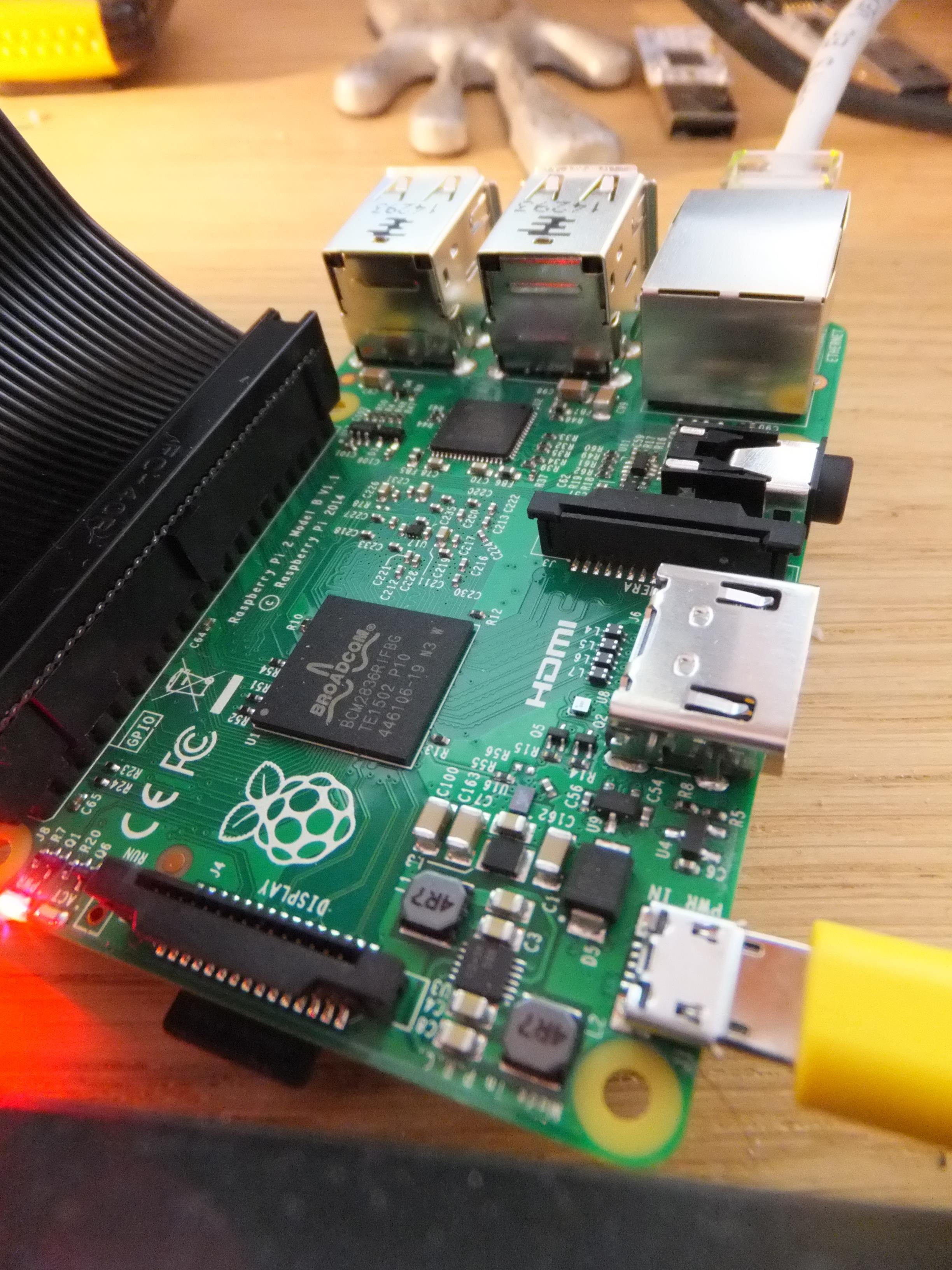
All images I've ever come accross that work on the Pi come bundled with SSH working out-of-the-box. This makes remote console access a breeze, and as long as you are familiar and comfortable with the command line, you can be up and running within a minute of powering up a Pi with a newly imaged SSD.
File Tranfer using WinSCP
When it comes to accessing files on the Pi's Linux file system, I find WinSCP to handle this very well. You can even open text files [such as source code] directly from the Pi, and WinSCP will handle the upload automatically when you save the file. On my LAN, I've *never* had a noticeable delay between hitting save and testing the updated code on the Pi.
I've been busy coding a Nixie Tube library, which is the first of [what I think will be] three libraries in total, along with the main program that will orchestrate everything. The other two libraries will be Nixie Driver and Nixie Display. These will work together to model the physical objects in code.
This initial test demonstrates that PWM is working correctly on the red LED, and BCD counting 0 to 9 is working correctly on the green LEDs.
One thing I've realised about this project, is that there is currently no indication for when a value is negative. The popular use for Nixies is to make clocks, so there is no use for this sort of indicator. A quick search found me three complimentary Nixie beauties - the IN-19A, IN-19B and IN-19V. The IN-19V is going to be the most used for value indication, as it has all the common symbols. The others are additional scientific indicators, and I'm tempted to get the lot. These are all visually and dimensionally compatible with my IN-14 tubes.
Just a quick log entry to share my initial foray into using the Adafruit T-Cobbler with the Raspberry Pi 2 to test output from the GPIO.
I decided the easiest way to get started on programming with GPIO was to use something with which I am already familiar. In this case, I am experienced in developing with the Arduino platform, and fortunately there is a Wiring library for Raspberry Pi called 'WiringPi'. Of course, the first and best test program to make is an LED Blinker :) After this, I tinkered with the SoftPWM library, but on retrospect I doubt I'll be using this in my final library code.
The Nixie Driver IC I am going to use is a K155ID1, which is a Russian clone of the SN74141.
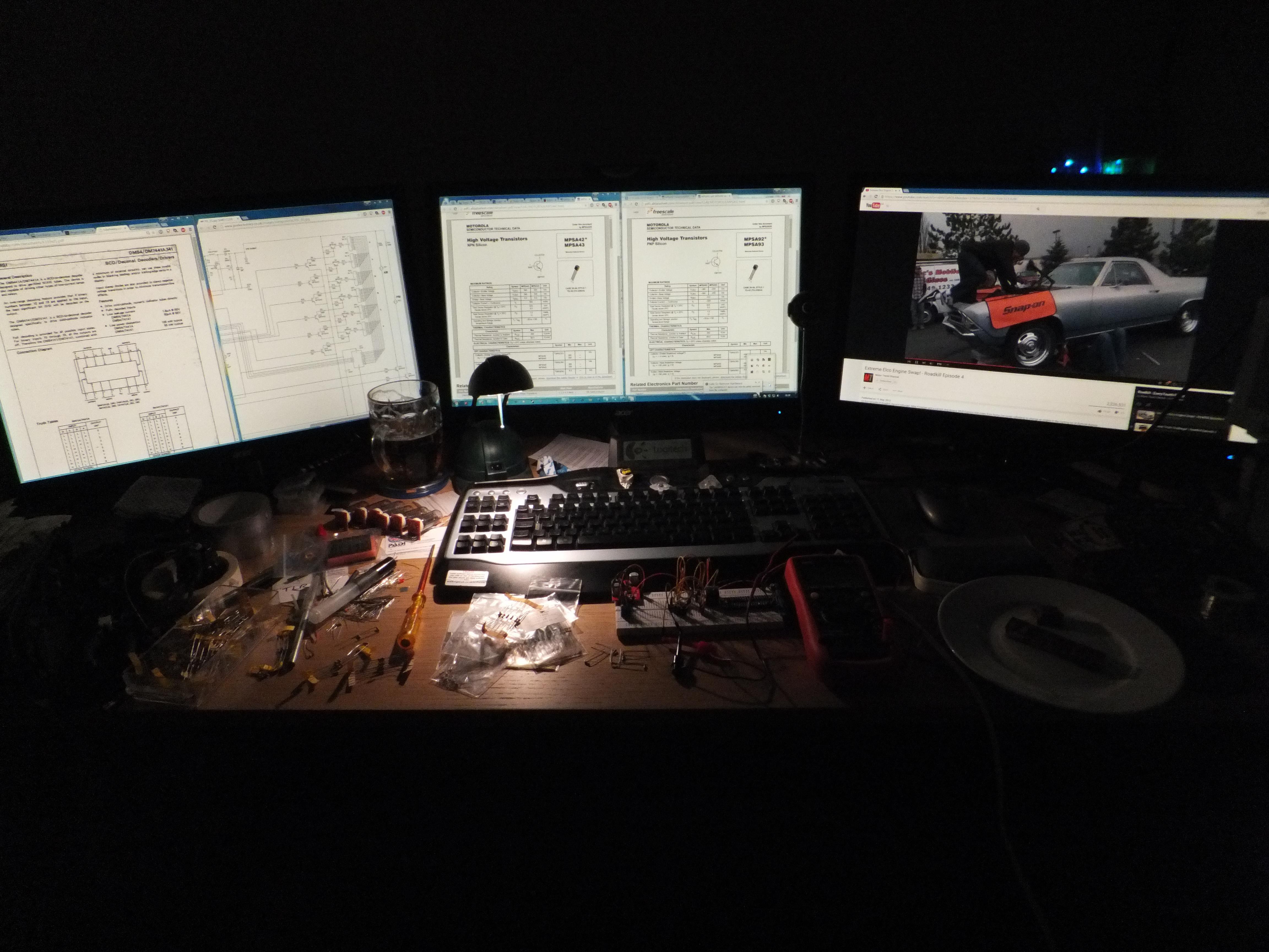
*Note: Had just finished testing the circuit, it was the weekend, and I fancied a pint :) Not wise to dabble in HV when inebriated.
Note 2: Always important to have chocolate on standby for thinking and calming!
The testing for these was not quite so complex as the Nixies. It ended up being a process of connecting up all the Neon bulbs in parallel, each with a resistor. This ensured the bulbs weren't fighting for voltage, and prevented any possible resistor overload.
Good to see that all the bulbs work...mmmm...glowy neony goodnesss. :)
Create an account to leave a comment. Already have an account? Log In.
Become a member to follow this project and never miss any updates

 Jeremy

 James Fossey
 ajlitt