ben biles
-
AVB on gigabit ethernet , USB2 ( on usbC socket ) multichannel IO, AES3 switched into mini xlr inputs outputs
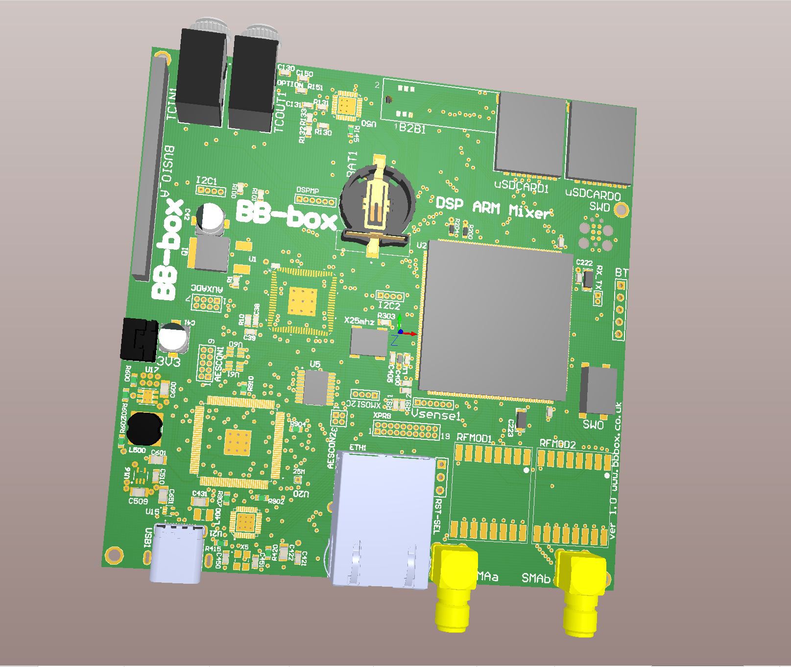
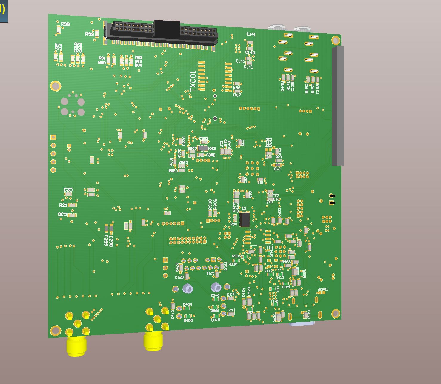
05/21/2020 at 02:13 • 0 commentsnew digi board with board to board connector to analogue board
B2B connector has enough high for RF shield
XMOS chip added for AVB,USB2 & AES3
AVB on gigabit ethernet
USB2 ( on usbC socket ) multichannel connectivity for osx and pc
AES3 IO switched into analouge mini xlr inputs outputs ( 8 channel in 4 channel out ) switching happens on analogue board ( room for 16 channel AES3 expansion )
individual analouge preamp channel pwr switching(individual CS lines run to run to preamps)
codec IC for mini jack IO timecode or other possible uses.
battery backup for TXCO and ARM timecode
Upgraded STM32F7 to H7 for 3 SAI ports to include CODEC IO for timecode IO
RF modules for TC RX digital audio or Timecode or both ?
![]()
2ppm TXCO clock for Timecode IO on individual codec connected to ARM via SAI port
![]()
-
XMOS AVB being added
04/04/2020 at 12:07 • 1 commentI tried to order an xilinx FPGA dev board and thought of implementing DANTE on that but it seams DANTE is more corporate development and big budget. Fair enough.
So now i'm adding an xcore-200 for AVB 1 gigabit ethernet audio IO.
I found the IC quite difficult to route and i'm not entirely convinsed I can get more than 8 channel in and 8 out over single TDM data lines. I only have 1 in and 1 out left on the ADAU1467 DSP.
but , 8 in 8 out and possible 16 in 16 out on ethernet is OK !!!!
I might be able to throw in some AES3 IO to from the same chip if I get good at using there IDE.
I'm hoping to be able to power off the XCORE-200 if no ethernet or AES3 is in use to for power saving. I think it will probebly use 1amp at 3.3v when all the channels are up !
-
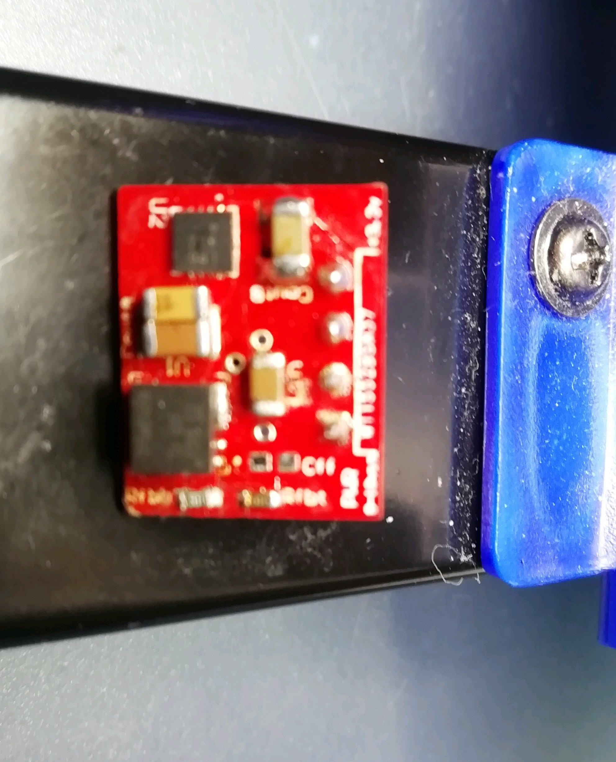
15mm x 17mm 3.3v 1.8amp max module
03/11/2020 at 05:52 • 1 comment15 x 17mm 6v to 20v input 3.3v output 1.8A
-
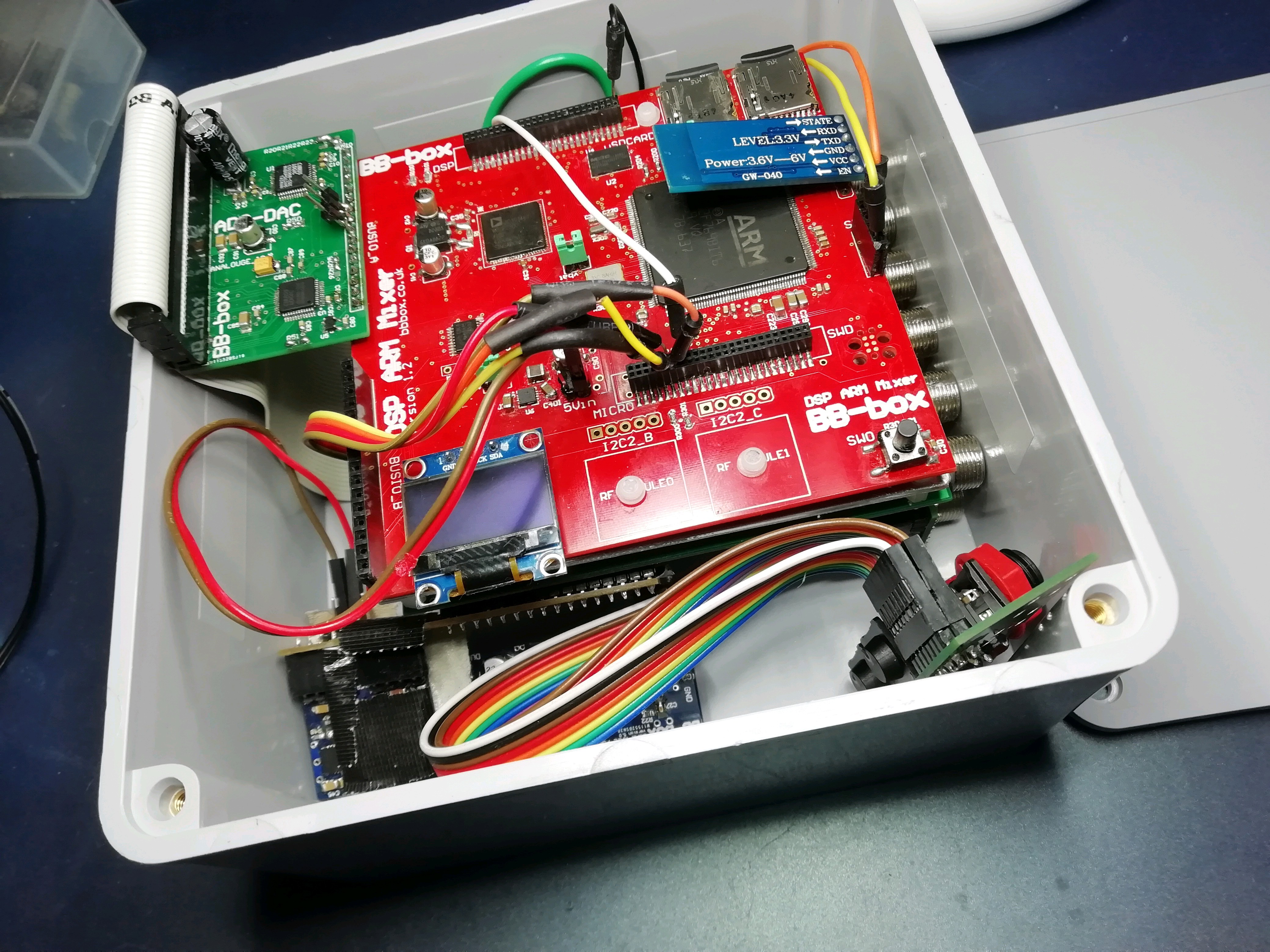
into the square box :)
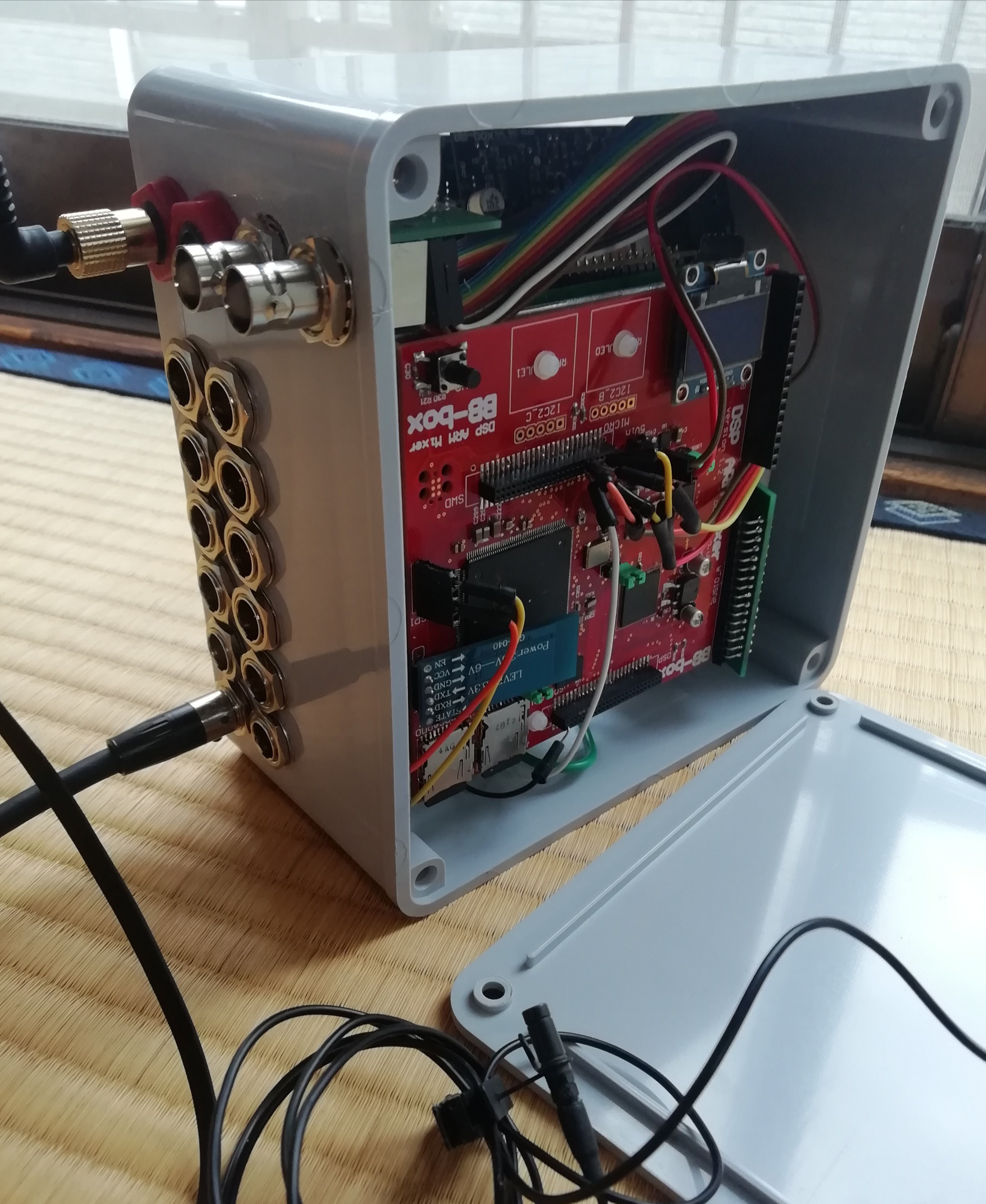
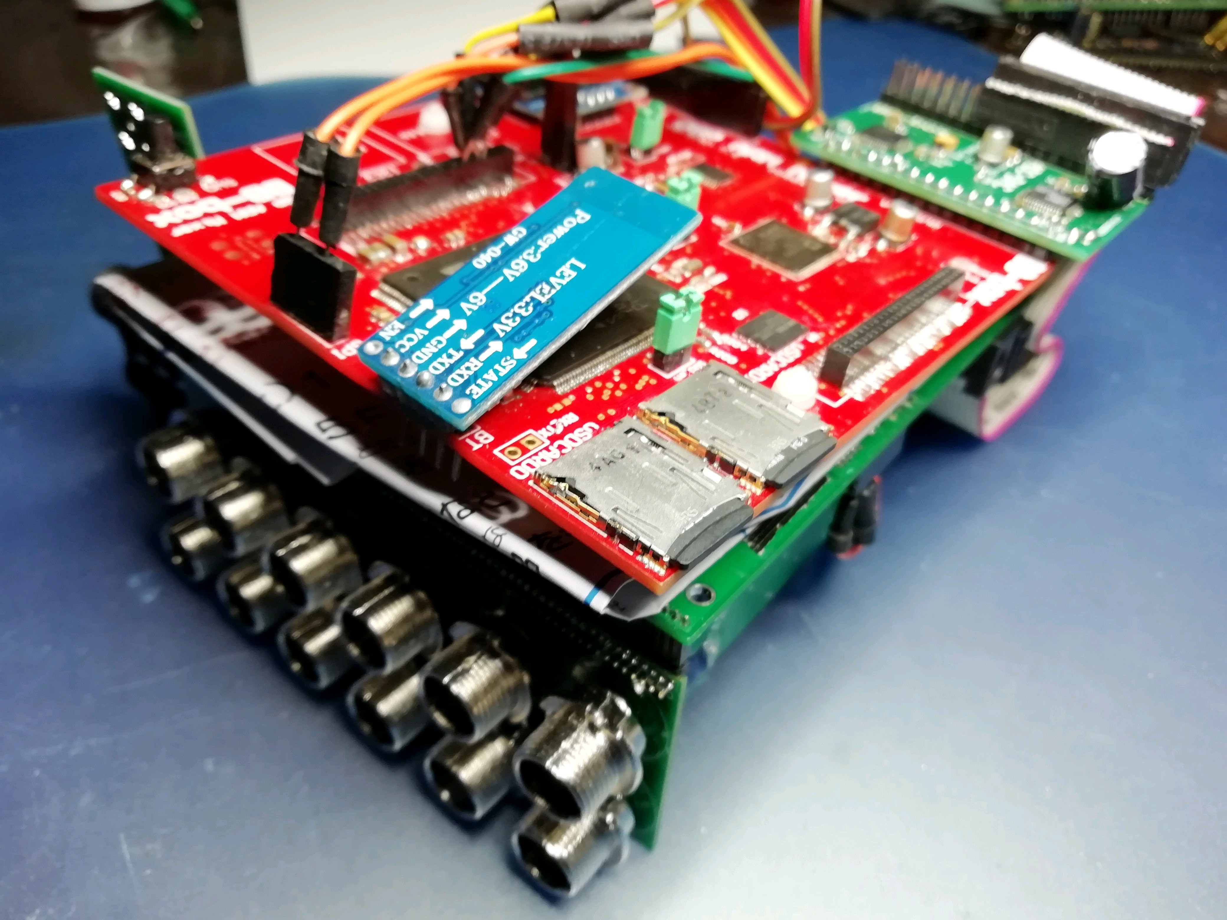
01/28/2020 at 06:07 • 0 commentsHers the Digi side of the new box with the panel off.
Its ABS plastic ( mock up only ! ) if everything fits in properly and I learn how to draw a CAD box ( currently learning the free software Design Spark by RS ) I will get an aluminium version of the same thing made. This case is not water proof so I need to learn how to make a channel for a rubber compression gasket I think.
The ADC DAC card 1 is at right angles now and there is plenty of room at the back although nothing holding it all in place at that side. I think the EMI shield could extend outward in the final design to be a kind of mounting bracket for PCB's to box! I might mount the 1" OLED somewhere on the box just for debugging.
The timecode IO is on massive BNC connectors. separate for in / out. This is mainly because there are so many annoying timecode cables these days that are impossible to repair in the field I though it better to keep that simple. The mini XLR are just part of the design trade off with size, there's just no way I will get another 8 connectors on there if I used full size XLR and i decided break out D socket to XLR's are annoying if your only using a few channels of audio.
I'm thinking there will be 16 channels of AES3 mini xlr on the rear side of the case since that's were the 2nd TDM IO port is on the digi board.
There should be enough room for 12v of lithium iron internal battery above the 1" OLED in this pic. I did put a 4 pin power hirose connector on the box since I'm not sure where it should go yet. maybe by the timecode sockets.
![]()
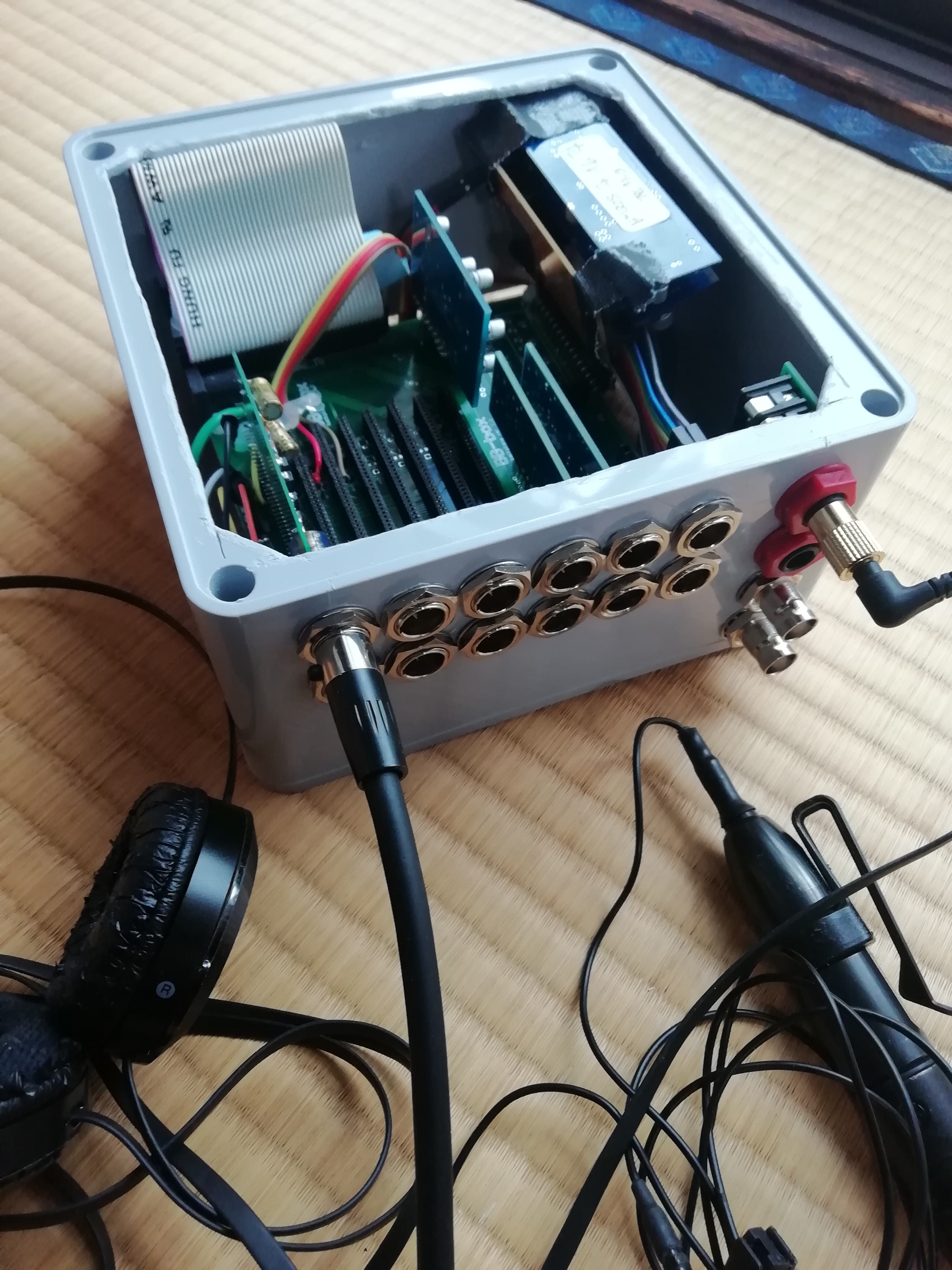
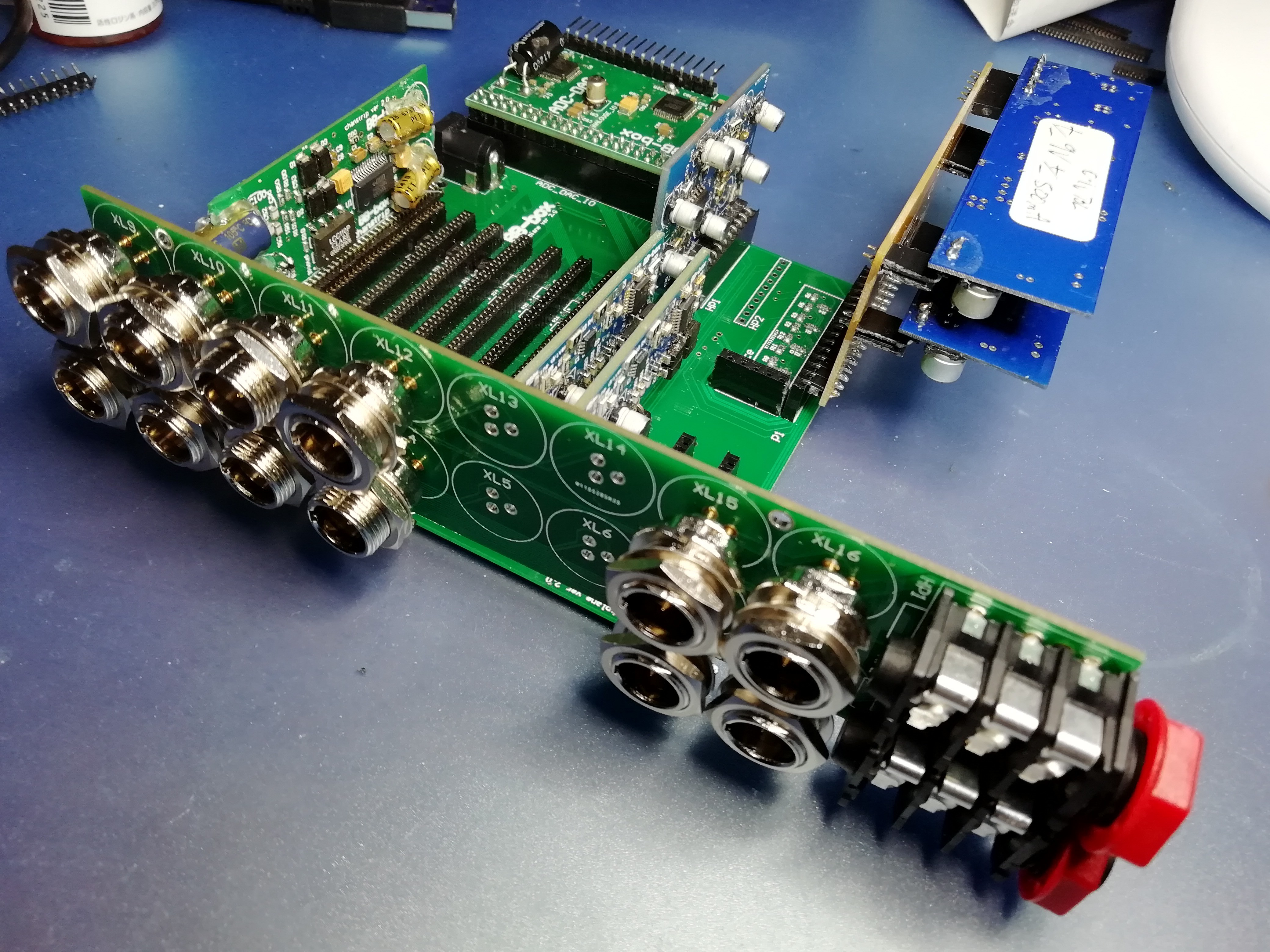
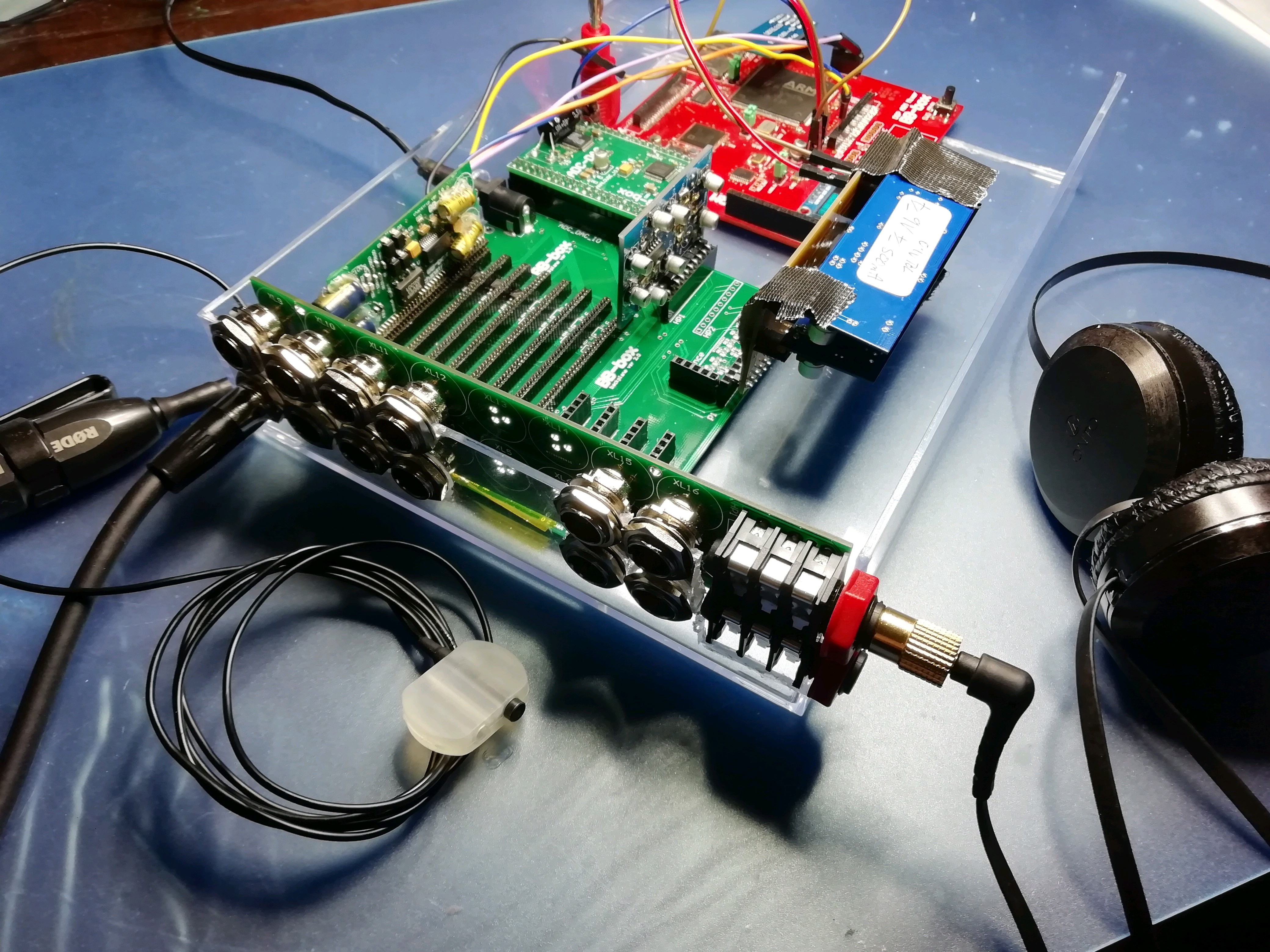
It reminds me of a little mac mini ! This is the analogue side, the big ugly 40pin IDE
cable will go ! its just bridging the ADC DAC IO and power. By luck they line up pretty well when the ADC DAC card is at 90 degrees. I just need some right angle double row headers and the card will just plug right in :)
![]()
I only have one preamp plugged in and I have only made 4 of the new deisgn so far!
I only have one in there mainly in case I dangle a oscilloscope crocodile connector and short some 48v phantom and blow all the cards ! I do cover the phantom power via's and anything exposed with tape or glue after learning why they call it phantom! Yep it happened to 4 cards a year or so ago !
Now there's 2 x line drivers in there and 1 headphone card. Its enough for most testing. I'll probebly put the programmer in the box and add a usb port to the case. Just easier than dangling an external programmer if I want to take the thing with me to the park and work on some code.
-
New box
01/26/2020 at 12:14 • 0 commentsIf I bend the ADC DAC card to it aims downward, this should fit!!
-
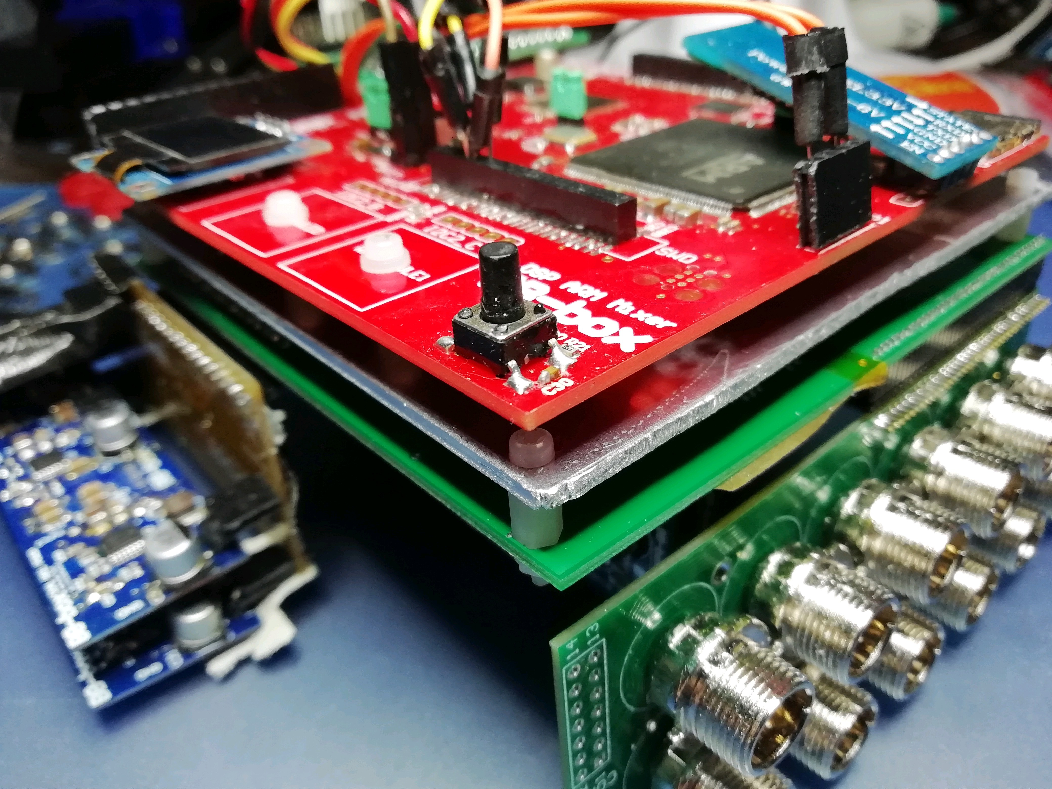
2mm aluminium sheet for emi shielding. Not connected to either digi ground plane or analogue.. Should it be?
01/20/2020 at 14:41 • 0 commentsAluminium emi between digi and analogue board
-
Field recorder gets shrunk down into a small box.
01/18/2020 at 08:49 • 0 commentsMaking the field recorder into a small square box 15x15x7cm
The plan here is to mount the DSP digi card and analouge main board to
a 2mm 10x10cm sheet of aluminium which will hopefully shield the EMI from
digi board to analogue board ( preamps )
![]()
-
Clear demo case, mini xlr IO with 2 x 1/4" headphone jacks
01/09/2020 at 03:58 • 0 commentsPerspex demo case with mini xlr IO and 2 x headphone 1/4 inch jacks
-
out of the old box without a new box to move into
12/30/2019 at 14:52 • 0 comments![]()
ok finally have enough bits to get the new analogue board running without a box for it !
I'm tempted to just buy some aluminium sheet and just make the prototype box ! I watched some interesting videos of people using brazing rods to weld aluminium with a gas torch. If not aluminium maybe just some acrylic sheet and epoxy glue
1/ The headphone sockets should be on the underside of the the connector board to allow more clearance with the miniXLR sockets and to fit into the corner of the box better.
2/ The ADC - DAC card should be flush with the top of analogue and Digi boards allowing the power and SD cards to be flush with the edge of the box. Also digi board is not level with analogue board!
3/ power back plane could do with shifting all the pwr cards left 2 cm's
4/ the SPI lines for preamp gain control will be 16cm from digi board ! a bit far !!
5/ I should put the V sense dividers and reference on the power backplane. Just thought of that as I type this !
6/ dump OLED screen and use that area for 12v to 3.3v 1amp DC-DC rather than steeling 5V power from the analouge pwr board.
7/ where to put the isolated 9v - 18v 12v regulator and do I include a charger for maybe 4 or 8 x 18650 3.7v Battery's ?
-
new analogue board
12/29/2019 at 09:12 • 0 commentshere's a pic of the new analogue board.
It has optical isolated power switching for preamp channels
Also has +/-5 and +-10v power monitoring with reference 3.3v using
resistor dividers.
It all looks bigger than it will be when its soldered together without
headers as connectors !
the power backplane on the right will probebly get smaller.
It will have 8 analogue differential channels in and 4 out.
2 high quality stereo headphone drivers
and timecode IO.
The ADC DAC board at the back will bridge over directly to the digital
board.
![]()
Multichannel Audio DSP Field Mixer Recorder
bluetooth app controlled professional portable DSP mixer.balanced audio IO,phantom power,flexible routing,ISO recording. timcode. AVB audio.