Close
0%
0%

OSHChip V1.0

A tiny processor board the size of a 16 pin DIP with Bluetooth Low Energy

Similar projects worth following
OSHChip is one of the smallest processor boards available, and is the most powerful available in a 16 pin DIP format. When I first used DIP-16 devices, the complexity was about 4 to 100 gates. OSHChip V1.0 is about 3,000,000 gates (including 256 KB Flash memory and 32 KB SRAM).
And it includes a Bluetooth Low Energy radio (BLE)
It is compatible with the breadboards that are commonly used by electronic hobbyists. The pins are directly designed to work with these breadboards, they plug in easily and don't damage it. Unlike other processor boards that are far larger, OSHChip can be plugged into the middle two rows of a breadboard, and it doesn't cover the connected holes that you will be connecting to.

NEWS: 10/23/2016 The pins used in OSHChip can now be purchased on Tindie and used with your projects and breakout boards: http://oshchip.org/products/Flip-Pins_P

8/11/2015 11:00 PM

Hi dear reader. As you can probably see this is my first project on Hackaday, so I am still finding my way around. There is a lot I could write about for this project and would welcome some guidance in the comment section of what areas you would be interest to read. Here are some examples of what I could write about:

  • The origin of the idea for OSHChip, and how it has evolved from 11/4/2014 till now
  • The goals and tradeoffs for OSHChip V1.0
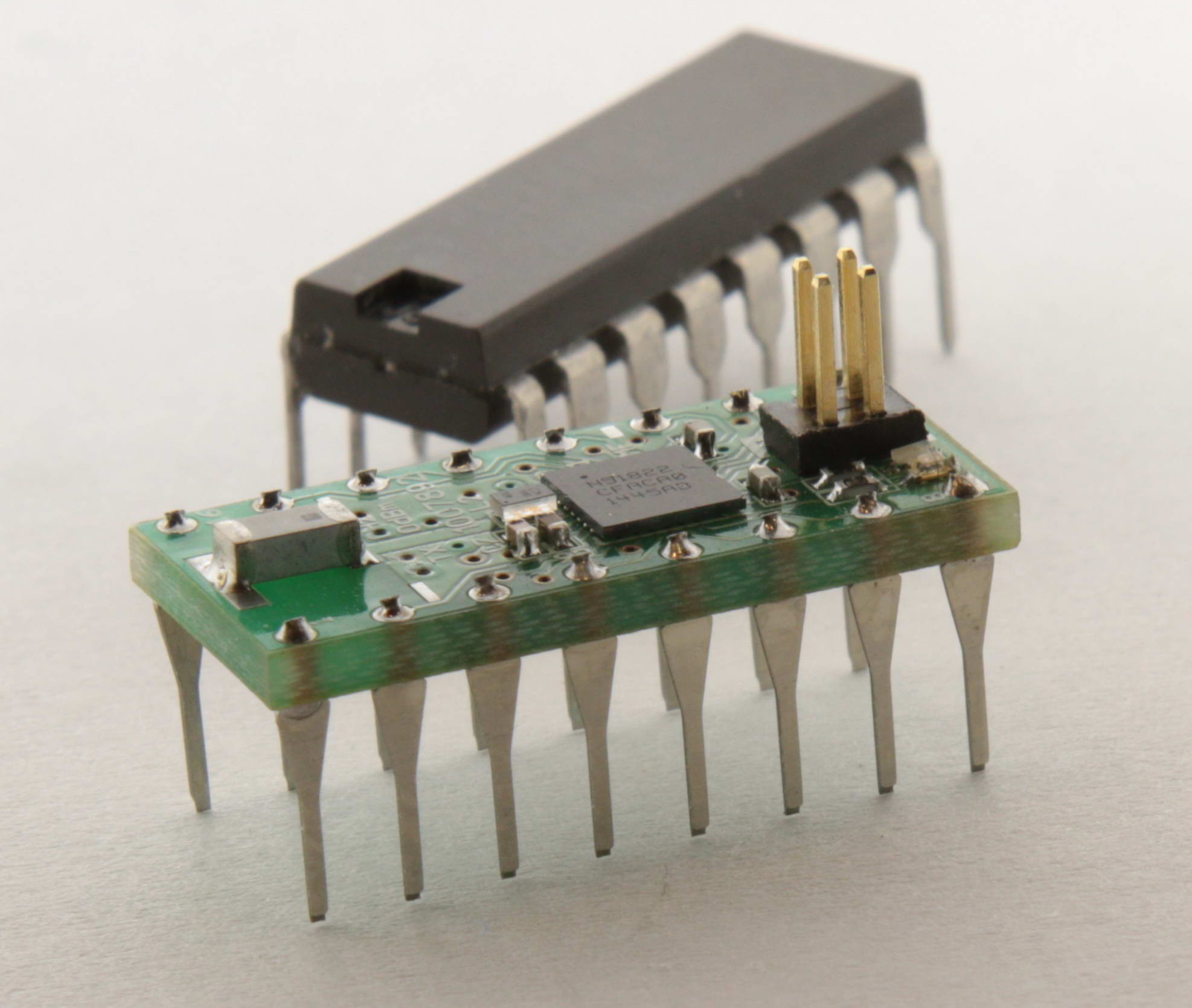
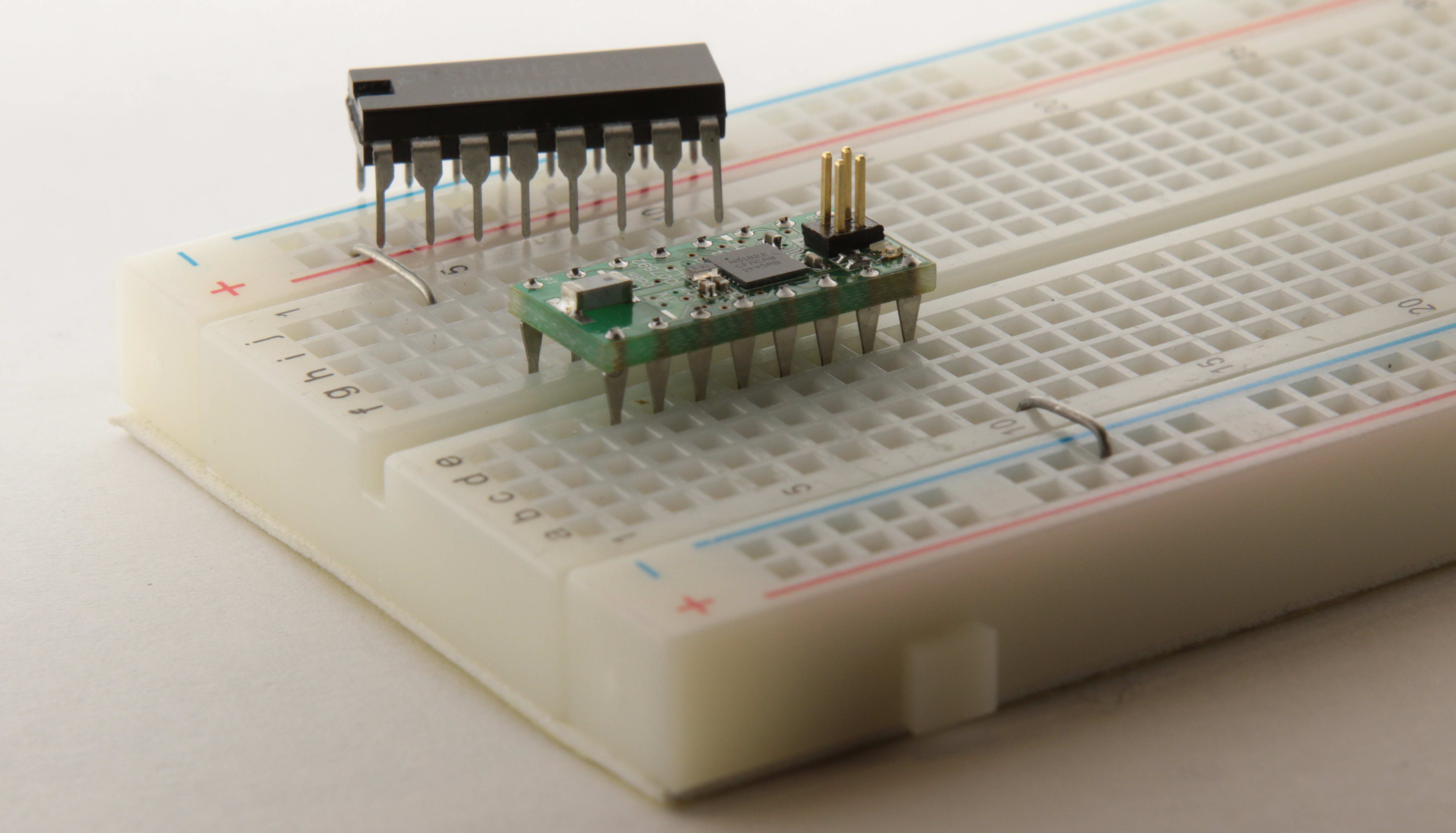
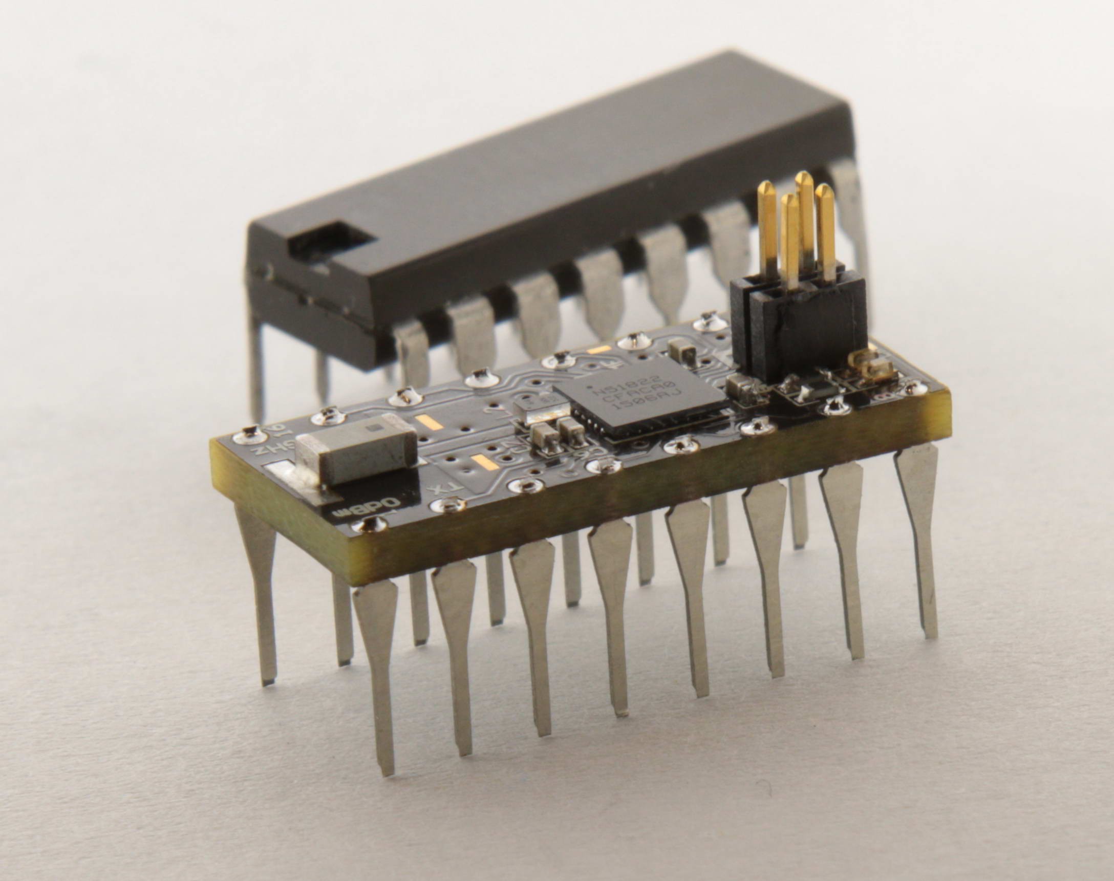
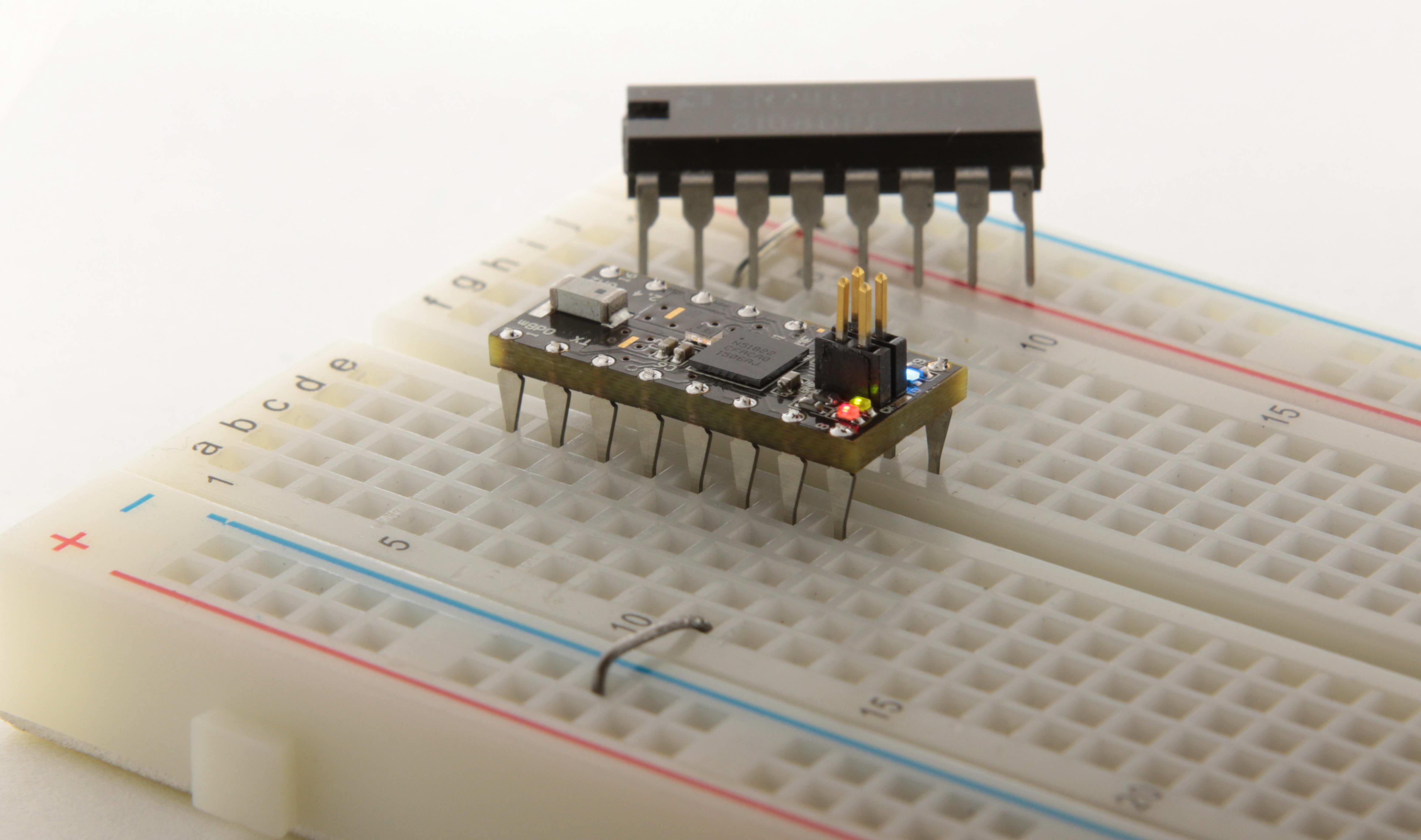
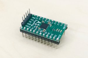
  • The design of OSHChip V1.0
  • Building the first prototype
  • Performance related information
  • The 4 different software environments that I would like to support
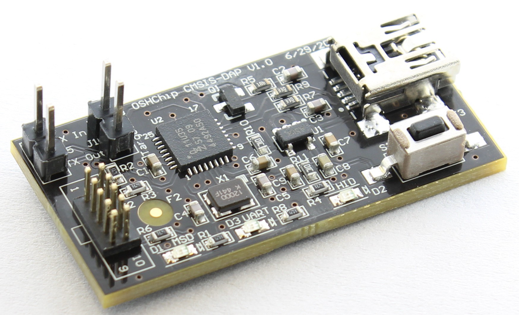
  • The programming hardware and software OSHChip_CMSIS_DAP_V1.0
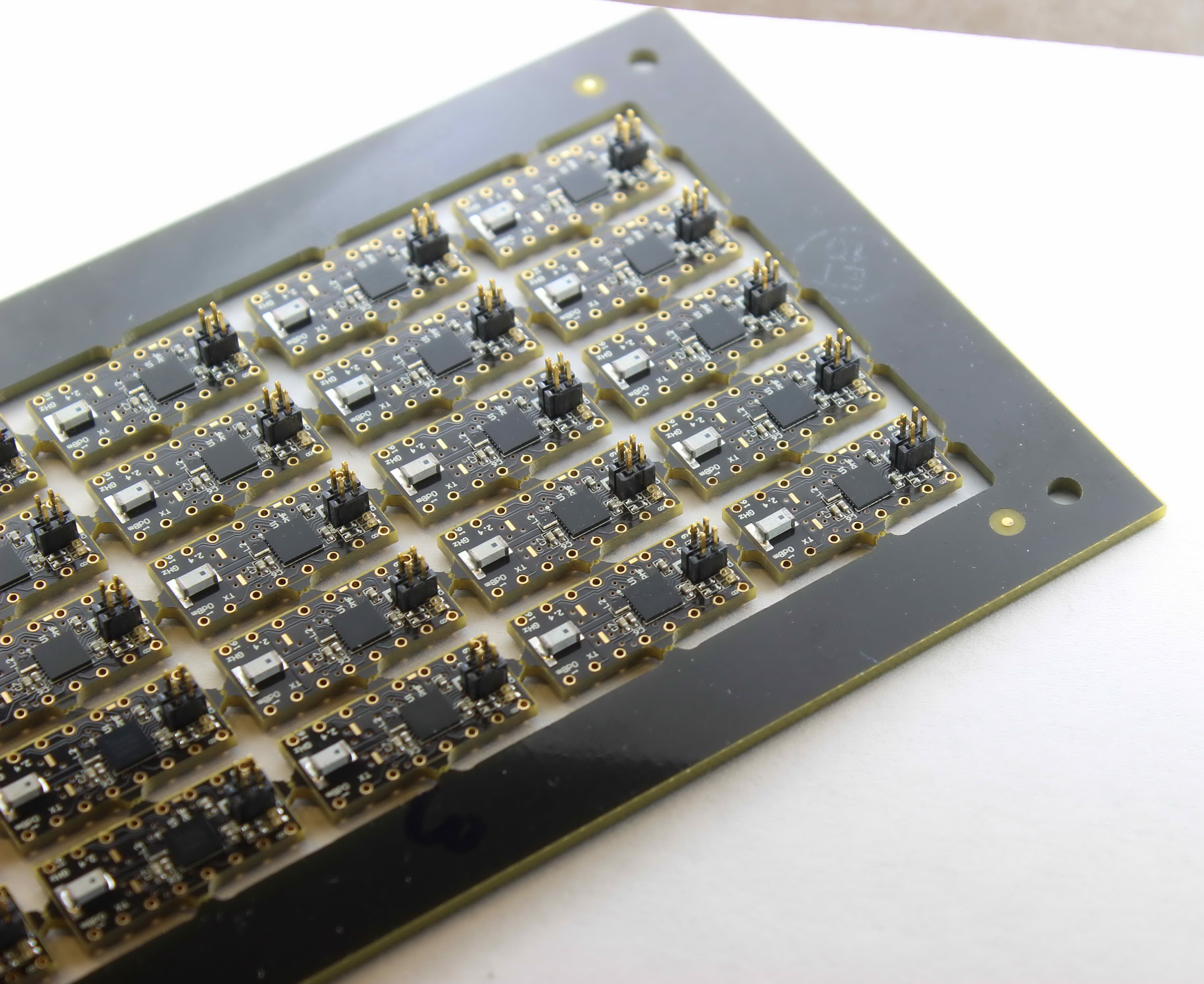
  • The first "mini production build" of OSHChip V1.0 and OSHChip_CMSIS_DAP_V1.0
  • Thinking about the web site www.oshchip.com
  • Thinking about Tindie
  • Thinking about Kickstarter
  • Detailed schematics and Bill Of Materials
  • How to figure out the price
  • How to predict production batch size
  • Looking for people that would like to join the project and contribute
    • For the web site
    • For a forum
    • Derivative devices
    • "Companions" (the name given to add-on boards , like shields or capes)
    • Brainstorming
    • Tutorials
    • Example designs
    • The OSHChip library
    • Building a community
    • Chip to smart phone communications
    • Chip to Chip communications
    • 3D printed shells, diferent styles, colors, and maybe cute "Hood Ornaments" for your chips.
  • Please suggest additions to this list.

  • 1 × AMCA31-2R450G-S1F-T Chip Antenna 2.4 GHz
  • 2 × CL05C120JB5NNNC Capacitor 12 pF 0402 50V NP0 5%
  • 4 × CL05B104KO5NNNC Capacitor 0.1 uF 0402 10 V X5R 10%
  • 1 × 04025C102KAT2A Capacitor 1.0 nF 0402 25 V X7R 10%
  • 1 × EMK105B7473KV-F Capacitor 47 nF 0402 16V X7R 10%

View all 15 components

  • The I.C. Pins used in OSHChip are now a product!

    Philip10/23/2016 at 10:04 0 comments

    Several of the people that have looked at this project have asked about the I.C. pins I use. It took a while, but I have now designed and manufactured a version that is easy for anyone to use.


    http://oshchip.org/products/Flip-Pins_Product.html Detailed product description

    For sale at:
    At Tindie Minimum order is about $20

    At EMSL 8-Pins 14-Pins 20-Pins Minimum is 10 pieces

    At Sparkfun 8-Pins 14-Pins 20-Pins They sell as little a a single part.

    If you buy some and like them, please write a review and tell your friends.

    If you have any issues, please let me know.


  • Today is the DAY!

    Philip01/21/2016 at 21:53 0 comments

    1/21/2016 12:50

    I'm going to write a bit about the launch tools.

    I've been working hard on the new web site to replace the crappy single page web site, and I realized that if I waited till it was perfect, I would never be done. Best is the enemy of better, better is the enemy of good, good is the enemy adequate, etc... I think I am somewhere between adequate and good. Please have a look at www.oshchip.org

    Mailchimp

    So pulling the trigger involved taking all the emails that project followers have been sending me based on the request that was at the top of the project page. There were 126 of them. Chris Gammell recommended mailchimp as a way to handle sending out that many emails. I was certainly worried that my ISP would probably shut my normal email down, if I sent that many email over a short time from a normal email account.

    Mailchimp was a delight to use. Very straightforward, good explanations, very clean layout, easy navigation, and after pulling the trigger (about 45 minutes ago) , I got to see their analytics, and for a free service, it is amazing. I can believe I was contemplating emailing from my personal account (actually I can, but you get the picture) Here is the email, please share this URL: http://eepurl.com/bNhGnP

    Google Forms

    Google Docs has a Forms creation capability, and I needed a "Register for a monthly newsletter" type form. It was relatively easy to create, and you end up with a link to the form (for filling it out mode) that does not require you to be logged into anything, which is what you would want for this type form. So you include the link to the form in the outgoing mail, and recipients click it and fill in the form, hopefully. The form results are then added to a spreadsheet, that you need the account password to login and view. Pretty nice integration, relatively easy to setup and use, but not as easy as Mailchimp

    The New Website: Jekyll

    I probably wasted 2 months last year trying to get my new web site up and running with Wordpress. It was a constant frustration as I was always trying to figure out how to get it to do what I wanted. I needed something clean and easy to use. I saw a web site I likes http://electronut.in/ (On Hackaday https://hackaday.io/electronut He has a real cool project snapVCC) and read his blog: http://electronut.in/switched-to-jekyll/ and wow did it resonate with my painful experience. So I asked if he could make a copy of his web site for me, strip out all his content, just leaving the scaffold for me to build my web site on. The result is the new website. I could go into details, but there is more than enough info that Google will find for you.


    Still to do: A forum, examples, tutorials, FAQ, .... But good news is I am getting orders.

  • Final sprint before starting to sell OSHChip V1.0

    Philip01/10/2016 at 22:14 3 comments

    1/10/2016 14:28

    I am finally getting the replacement web site ready so that I can start selling OSHChip and its programmer/debugger. This will replace the crappy single page site that I have been using up to now at www.oshchip.com . Since November 2015 I have had an email link at the bottom of that page with the following:

    OSHChip and the supporting programmer/debugger interface will be going on
    sale around the end of November or December 2015. If you would like to
    receive a notification email when this occurs, please send an email to
    philip@OSHChip.com 
    I've been getting emails at about 2 or 3 a week since then, until 3 days ago, when lots more started arriving, and I didn't know why. I found out that this project got listed on the home page of www.hackaday.com as a featured project, and it happened to coincide with me changing the first picture (the one that shows up with the project name) for the project to my favorite pic that has the production black version (prototypes had a green PCB) of the chip.

    So this was just an excellent set of things coming together: Favorite pic, about to announce that OSHChip would be available for sale, and front page of Hackaday. As you may be aware, after I talked to several friends about the challenges of running a crowdfunding campaign, I decided to self fund this project, accepting that I wouldn't have the high visibility of a crowdfunding, but also I wouldn't have the stress. So last year (see previous logs) I designed and built OSHChip and the programmer/debugger on my own dime (a lot of dimes!), and have had 200 OSHChips and 100 programmer/debuggers sitting on my desk, waiting for a supporting web site. After a very frustrating time trying to create a site with Wordpress, I enlisted the help of https://hackaday.io/electronut who has a web site with the look and feel I wanted, and he got me setup with the less complex Jekyll approach to web sites. That's what I am working on now, and in a few days, it won't be complete, but it will be good enough (I hope) to support starting to sell my project.

  • It's never too late to Procrastinate!

    Philip12/01/2015 at 21:38 0 comments

    12/1/2015 @ 1:32 PM === 9:32 PM UTC

    You may have noticed that this project is entered into the https://hackaday.io/project/7813 Square Inch Project contest. Check it out.

    Among the rules are some deadlines, including

    1. Finalized schematics, BOMs, and design documents, as outlined above, must be posted on your project's page by December 1, 2015.

    All these deadlines are at 23:59 UTC on the specified date.

    So I just finished setting up the GitHub repository for this project. All the sources and the Open Source License (CC BY-SA 4.0) can be found here:

    https://github.com/OSHChip/OSHChip_V1.0_Docs


  • Over due project update

    Philip11/26/2015 at 11:15 0 comments

    11/26/2015 @ 3:00 AM

    Current status:

    I started this project on November 4th 2014, and received the first batch of 200 OSHChips from the EMS a few days before November 4th 2015. I had already scheduled a trip to Australia, departing on the 4th, so off I went with 1 part to play with and show friends in Oz. Exactly 1 year from concept to first completed batch.

    I have developed a simple test program for the OSHChip. In my experience, most chip failures are I/O pin related since they are exposed to the outside world. ESD can kill a pin outright, or it can damage the I/O cell such that it fails much sooner than typical. The common failure modes are

    • Driver can't drive high or low or both
    • Pin stuck high or low
    • Input doesn't work , stuck high or low
    • Pull-ups don't behave as expected

    I wanted to be able to test the OSHChips without needing a test fixture (for now) so the test program runs the test and blinks a distinctive pattern on the on-board LEDs indicating either pass or fail. There is sufficient program-ability that the I/O cells for each pin can be tested from within the chip. For example, to check that the pins aren't shorted high, the pin is configured for input with a pull-down resistor, and the input is read. If it doesn't read '0', then there is a stuck-high problem or the pull-down isn't working. I wrote 7 such tests that exercised each pin for all of the above problems. The other common problem that kills chips is over heating, but that is an in-system issue, and not likely for a new chip/assembly. It is also very unlikely, given the very low power nature of OSHChip.

    I have received and tested all 200 OSHChip_V1.0s from the EMS and the yeild was pretty good:

    • 197 tested with no errors
    • 1 part had a low intensity red LED
    • 1 part was completely dead, and didn't respond to diagnostic probing through the SWD port, so I replaced the BGA and it works fine now. So either a bad chip, or bad assembly.
    • 1 part is failing the diagnostics, but I have not had time to identify why.

    I have also successfully used pyOCD to access the on chip factory configuration registers, which include a unique ID for each unit, so I can record this info for each unit that ships to an end user. On my crappy web site at www.oshchip.com there is now an email link for people to request to be put on a list for a notification email when I start selling OSHChips. (Actually a few special early access users have received the first 14 parts).

    Some very simple test programs that use the Bluetooth Low Energy radio have been written, including one that sends out a text message of "Ping xxxxxxx" where x..x is an increasing number, once per second. I started it about 5 or 6 weeks ago, and left it connected to 3 dead D cells (series voltage was about 3.05V) while I went to Oz for 2 weeks. When I returned it was still going, and was up to about 3600000 . Batteries series voltage is now 2.95V.

    As I have entered this project into the https://hackaday.io/project/7813-the-square-inch-project I have already met deadline 1. Deadline 2 is partially done: BOM of final assembly. Still to do: Source EDA docs, Gerbers, drill files etc. I have a github account setup for this, and will do this in the next few days. When the time comes, please vote often and early for this project :-) Deadline 3 is also partially complete, as I already have shown pictures of the final product.

  • Some pictures from a photo shoot

    Philip09/11/2015 at 06:53 2 comments

    9/10/2015 @ 11:50 PM

    I have been working with a magazine editor on putting together a short product announcement. This required some photography, and my skills in this domain are minimal, and my camera equipment is barely better than a box with a hole in it. So at 10:00 PM yesterday, as things got desperate, I called my friend Mike to see if he could help me get some sharp, high res, closeup photos. Although we didn't have a macro lens available, I think we did pretty well. We finished up around 1:00 AM this morning. I owe him and his wife dinner at a very nice restaurant!. The following pictures have been cropped and have lower quality resolution than my masters, because I didn't think Hackaday.io would appreciate me uploading 5 images, each about 4 megabytes.

    The green PCBs are the prototypes, the black ones are the initial production. For your viewing pleasure:

    Prototype

    Prototype with his older buddy

    Prototype in its native habitat

    Production OSHChip_V1.0 with his older buddy

    Production OSHChip_V1.0 in its native habitat, with LEDs turned on


    That's all for now.

  • Hatching the first batch !!!!!

    Philip09/02/2015 at 17:30 0 comments

    9/2/2015 @ 10:31 AM

    The first batch of OSHChip_V1.0 boards and their companion programming boards OSHChip_CMSIS-DAP-V1.0 have been hatched and I am now checking them out. So far every things seems to be perfect (no blue wires needed), and the contract assembly company (sometimes called an EMS, Electronic Manufacturing Service) has done a beautiful job, and right on schedule. Here are some baby pictures:

    OSHChip_V1.0 panel

    As you can see, the chips are still in the panelized form, without their legs. The debug connector on top is connected to the programmer (see next picture), and a simple test program is loaded that flashes the 3 LEDs that are next to the programming connector. One mild disappointment is that the green LEDs are not as bright as the original prototypes. Between the building of the prototypes and the first batch, the manufacturer of the green LEDs discontinued the product. Because these LEDs are tiny (0402 package) there are very few options. I picked the one I thought was the best substitute, but did not get to try them in circuit. I will investigate if I can get it a bit brighter with a change of the series resistor. If it makes a significant improvement, then I will need to rework 200 OSHChip_V1.0 PCBs, replacing an 0402 resistor on each. If you have never tried replacing parts this size, let me tell you, it is really challenging! So after a bit more testing, the boards will go through a proprietary de-panelization process that leaves smooth edges on all 4 sides, and then they will go back to the EMS for final assembly of soldering in all the pins.

    OSHChip_CMSIS_DAP_V1.0

    So this is the programmer that takes USB and provides 3 services:

    • USB to CMSIS-DAP programming with a SWD connection to the target. Use this with the Keil IDE. This should be able to program any processor that the Keil IDE supports (there are hundreds) that can be programmed via SWD. There is also support for debugging with GCC's GDB debugger, via pyOCD
    • USB MSD (Mass Storage Device), shows up like a USB memory stick/drive, named MBED. You can drag and drop .HEX files to this drive, and it will convert the file to the appropriate SWD pin wiggling and program a nRF51822 which is the processor on OSHChip_V1.0
    • USB to virtual COM port. The board provides serial I/O at LVTTL (0 to 3.3V) levels on the 2 pin header on the end of the board. These can be connected to anywhere in your system that has async serial I/O, so no specific pins on OSHChip_V1.0 . I haven't tested it yet, but it should work from 9600 to 115200 BAUD.

    Overall I am pretty excited!

  • The first batch

    Philip08/19/2015 at 21:30 0 comments

    8/19/2015 @ 15:00

    The PCBs for the first batch of boards were picked up from the PCB manufacturer, Bay Area Circuits .

    200 of the OSHChip_V1.0 boards. These are the processor/radio boards

    and

    100 of the OSHChip_CMSIS_DAP_V1.0 boards. These are the programmer/debugger/serial-to-USB boards

    I spent the weekend kitting all the components, just waiting on one item coming from Mouser to replace a small mess by Digikey. Parts arrived late Monday 17th, so too late to deliver to the assembly company. Delivered all the boards and parts kits to the assembly company on Tuesday 18th. Should have assembled boards in about 3 weeks.

  • Origin of OSHChip

    Philip08/17/2015 at 03:46 0 comments

    8/16/2015 @ 20:42

    The idea for OSHChip occurred 11/4/2014 and I have been working on it to the exclusion of pretty much all other projects.

    There were several goals I had in mind, all focused on a product for the hobbyist.

    • Package a high performance micro processor in the smallest package possible
    • Have the cosmetics of an IC (in particular, a 16 pin DIP)
    • Open source Hardware and Software (where ever possible, and be up front about any exceptions)
    • Bring professional class debug experience to hobbyists that have only had printf() and flash a LED
    • Compatible with the white breadboards used by many hobbyists
    • Create a platform for hobbyists to create standard chips that are used by others
    • Create a web site that supports a community of Chip designers and users
    • See how many people laugh at me when I am telling them I am creating a new type of fabless semiconductor company.
    • and more ...

    So I have been at this for 9 months, and I have built 12 working prototypes. I have ordered enough PCBs to make 200 OSHChips_V1.0 and 100 of the programmers, OSHChip_CMSIS_DAP_V1.0 . All the components have also been ordered and have arrived except for 1 screwup by Digikey, which should be resolved by Mouser tomorrow. I will the take all the boards and components to a PCB assembly company, and with the encouragement of some money, I should have assembled boards in early September.

View all 9 project logs

Enjoy this project?

Share

Discussions

Jeremy g. wrote 06/28/2016 at 21:50 point

do you sell the pins? I can't seem to find anything like them.

  Are you sure? yes | no

Philip wrote 06/28/2016 at 23:24 point

Hi Jeremy,

Thanks for starting to follow the project and your question. If you had looked through other comments, like Pablo's you would see you are not alone in wanting to get these pins. See https://github.com/OSHChip/OSHChip_V1.0_Docs/issues/1  for a discussion back in February of this year.

Here's what's new.  I have been working very hard on figuring out how to make these pins available in a hobbyist/maker format that is easy to use. The two big issues were that the etched pins are quite expensive and delicate until soldered into the PCB, and the fixture that I use to hold the pins in alignment for soldering is about $60 worth of CNC machining. While the fixture makes sense for my "volume" manufacturing of OSHChips, it wouldn't make sense for hobbyist/makers. I have now solved both problems, and OSHChip_Pins will soon be a product, and I will write a major new log to this project to announce the details.

Until then, I would like to have some discussions with possible users to figure out pricing structure and how to sell them. Would you like to help?  Anyone else?

  Are you sure? yes | no

Jeremy g. wrote 06/28/2016 at 23:27 point

love to help out. And thanks for the quick reply.

  Are you sure? yes | no

[deleted]

[this comment has been deleted]

Philip wrote 02/29/2016 at 19:19 point

Hi Pablo,

I have a very detailed answer here:

https://github.com/OSHChip/OSHChip_V1.0_Docs/issues/1

Also just scroll down to the answer I gave to esot.eric on 9/11/2015

  Are you sure? yes | no

Philip wrote 06/28/2016 at 23:26 point

Hi Pablo,

Please see updated info in my answer to Jeremy.

  Are you sure? yes | no

Philip wrote 10/23/2016 at 09:49 point

Hi again, 

The pins are now available as a product for all hackers and hobbyists to use.

    http://oshchip.org/products/Flip-Pins_Product.html

    https://www.tindie.com/stores/OSHChip/

Please have a look and let me know what you think.

  Are you sure? yes | no

Iurii Plugatariov wrote 02/28/2016 at 23:41 point

Hello is it possible to buy now this kind of chip?

  Are you sure? yes | no

Philip wrote 02/29/2016 at 00:12 point

Yes, OSHChip went live on Tindie a few days ago.  https://www.tindie.com/products/OSHChip/oshchip-v10/

and the programmer:

https://www.tindie.com/products/OSHChip/oshchip-cmsis-dap-v10/

I think it is time for me to write a real update for this project  :-)

Thanks for your interest.

  Are you sure? yes | no

Iurii Plugatariov wrote 02/29/2016 at 11:53 point

Thank you, I will make an order in a week. My project requires kind of size that you provided with that chip.

  Are you sure? yes | no

Luis Diaz wrote 01/13/2016 at 08:19 point

Hi Philip!

I really loved your project.  I'd love to join the team and work with you. I currently work in a educational section of a company and my job is to teach others to understand technology and build it. 

I know how to design pcbs and I also develop software and courses.

Will love to help you.

Looking forward to talk to you.

Grettings!

  Are you sure? yes | no

Philip wrote 01/13/2016 at 23:26 point

Hi Luiz, you can email me directly, philip@OSHChip.com to discuss how you could contribute. I'm looking for a few things specifically short term:

1) Tutorials and getting started examples

2) Some work on compilers/IDEs

3) People that really know a specific Arduino model or other common hobby board to help fill in a spreadsheet for comparing various boards to OSHChip.

To join the project follow the link near the top of this page, under the team heading.

I'm looking forward to talking to you too.

  Are you sure? yes | no

Bill Rowe wrote 01/12/2016 at 02:47 point

gorgeous work. Clearly a labour of lov

  Are you sure? yes | no

Daz wrote 01/11/2016 at 21:25 point

Cool

  Are you sure? yes | no

RoToRx88 wrote 01/11/2016 at 21:02 point

Wow guys, just found your project, it looks so cool ! :D
Want to buy one ! Good job !

  Are you sure? yes | no

Philip wrote 01/11/2016 at 21:43 point

Thanks RoTorx88.  Actually OSHChip is just one guy, me.  I just updated the description at the top of the page with my email, for people that would like an email when it goes on sale, which should be later this week.

  Are you sure? yes | no

Shpoople wrote 01/09/2016 at 05:45 point

Wow, I didn't know that the nrf51822 came in a WLCSP package. Talk about tiny

  Are you sure? yes | no

Philip wrote 01/09/2016 at 06:45 point

Hand soldering the first 12 OSHChips was a really challenging, as was PCB layout. At 0.4 mm pitch, the pads for the micro BGA balls are barely wider than the signal traces I am using. The pads are 0.008"  and the traces are 0.005"

  Are you sure? yes | no

helge wrote 02/03/2016 at 20:01 point

It would be interesting to see the fanout pattern for that. Are you using standard PCB manufacturers or HDI PCB services?

  Are you sure? yes | no

Philip wrote 02/04/2016 at 06:17 point

Hi Helge, the design is Open Source. You can find the layout on Github. Start here: https://github.com/OSHChip/OSHChip_V1.0_Docs  then go to Other_Files and download OSHChip_V1.0___PCB_Prints.PDF (because github won't render it correctly) , the fanout is on the first page.  Fortunately, as I only have 14 I/O pins, I was able to do almost everything with the outer ring of pads, and a single via in the middle that gathers up several ground connections and passes it to the other side to connect to the ground plane on the back.  So no magic HDI for this design, just .005 lines and spaces, and 2 layer board.

  Are you sure? yes | no

haroldmoore016 wrote 09/14/2021 at 14:48 point

Great Soldering!  :-)

  Are you sure? yes | no

zakqwy wrote 12/20/2015 at 17:27 point

Great boards--I really like the design. Forcing yourself into the narrow DIP constraint will make this infinitely easier to work with than many other options available.

Since space is a premium--might be worth looking into something like this: http://www.rohm.com/web/global/products/-/product/SMLP34RGB2W/

RGB on a single chip, 1mm x 1mm... although having three discrete indicators is also nice.

  Are you sure? yes | no

Philip wrote 12/21/2015 at 10:15 point

Thanks for the pointer. That RGB led would be a nice addition, and I might look at it for OSHChip_V1.1  .  I checked the current price, and at 100 off it is about double the cost of the 3 separate LEDs I'm using now.  At 1000+ it is somewhat closer. 

  Are you sure? yes | no

alpha_ninja wrote 12/07/2015 at 00:26 point

[verified: no design files missing]

  Are you sure? yes | no

alpha_ninja wrote 12/02/2015 at 00:47 point

This is your one-week reminder to upload design documents: https://hackaday.io/project/7813-the-square-inch-project/log/28566-design-deadline

  Are you sure? yes | no

Eric Hertz wrote 09/11/2015 at 12:34 point

Nice pins! They almost look like they'd also work in "machine-pin" IC sockets. Are they custom?

  Are you sure? yes | no

Philip wrote 09/11/2015 at 18:27 point

Thanks.  The pins are my own design. I tried working with traditional IC pin manufacturers, and faced minimum order quantity requirements of 750,000 pieces. Several other people have expressed an interest in these pins, so I may decide to sell them as well, so people can make their own boards to work with OSHChip and have a similar "look". I am currently designing a special fixture that holds the pins in alignment to assist in soldering them into the PCB.

  Are you sure? yes | no

Philip wrote 06/28/2016 at 23:29 point

Hi esot.eric,

Please see updated info in my answer to Jeremy.

  Are you sure? yes | no

Philip wrote 10/23/2016 at 09:53 point

Hi again, 

The pins are now available as a product for all hackers and hobbyists to use.
    http://oshchip.org/products/Flip-Pins_Product.html
    https://www.tindie.com/stores/OSHChip/
Please have a look and let me know what you think.

  Are you sure? yes | no

Luke Beno wrote 08/20/2015 at 19:32 point

Very clever project, I've always thought a chip level RF module would be an awesome product!

  Are you sure? yes | no

Philip wrote 08/28/2015 at 20:59 point

Thanks, really appreciate the interest.

  Are you sure? yes | no

peter jansen wrote 08/20/2015 at 01:31 point

Do you think that programming over-the-air would be possible, through the BTLE module?  If so, this might be framed as a lower-cost/smaller version of the Spark.io/Particle boards, using BTLE instead of WiFi, and locally programmable rather than requiring a web interface.  Those might speak to really different kinds of applications and audiences.

Very neat stuff!  I love how you've been able to squeeze it into such a small (but conventional) form factor. 

  Are you sure? yes | no

Philip wrote 08/20/2015 at 05:29 point

Firmware Over The Air (FOTA) is in active development both at Nordic Semiconductor (manufacturer of the CPU/Radio used in OSHChip_V1.0) and on the mbed site  https://developer.mbed.org/platforms/Nordic-nRF51822-FOTA/

Nordic has demonstrated this working.

Pretty much any BTLE software written for a board with the nRF51822 can use the libraries being created by Nordic and mbed. I hope that later this year my board will be listed as an mbed platform. Even without that, you can select any of the existing nRF51822 based boards on the mbed site, and the only difference to OSHChip_V1.0 is the pin assignments. A trivial header file can re-map the pin assignments.  The other end of the FOTA is a smart phone, and I believe that Nordic already provides apps to handle that end.

I hadn't emphasized this capability, because I have not actually done it myself.

Also, congratulations on your 2014 Hackaday Prize project getting into the final 5!

I'm honored that you visited my little part of Hackaday.io

  Are you sure? yes | no

ajlitt wrote 08/29/2015 at 22:39 point

Last I checked the nRF51822 FOTA support in mbed works great with the Nordic Android DFU app.  In fact it's possible (though painful) to develop and compile an app in the online ide on a tablet then download the resulting binary with the DFU app.

  Are you sure? yes | no

Similar Projects

Does this project spark your interest?

Become a member to follow this project and never miss any updates