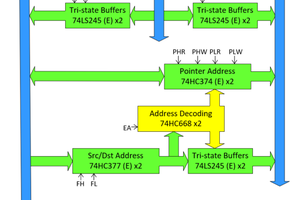
This project started as a way to understand how the 6502 processor works. Building an entire system with memory mapping and peripherals seemed daunting. There also didn't seem to be any good way to know what was going on inside the processor if something went wrong. So instead I decided to leave the ROM, RAM, and all of the peripherals out and use the PC for those functions so I would have more control over everything.
The first version used an MSP430 that communicated with the PC using a USB UART cable. Fetching or writing every byte every cycle over UART limited the speed to about 100 bytes per second due to the USB latency. Later I added a 128k SPI SRAM to hold a copy of the memory stored on the PC that would sync 10-20 times per second. This raised the speed to almost 20,000 cycles per second, which is only 0.02MHz. Next, I ported the code to an STM32F429 board. This is much faster and can hold all of the memory internally, which raised the speed to about 0.8MHz, which works well for testing code.
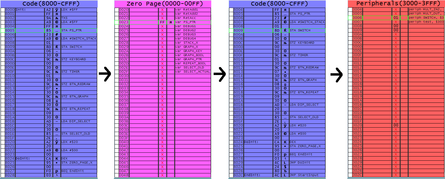
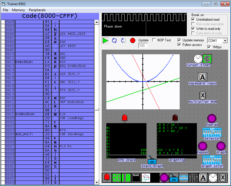
The software on the PC shows the entire 64k of the memory map and can be set to jump to the address the processor is accessing. Different sections of memory can be color coded. This really helps show exactly what the processor is doing every cycle and what values are modified every cycle. Also, when the processor is paused, individual bytes can be modified directly to test. Here are four consecutive views of the memory viewer that show how it jumps to show what the processor is doing:
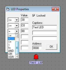
The peripherals can easily be dragged and dropped in the program. It is much easier to drag and drop a bunch of LEDs into the program than it would be to hook those up on a breadboard.
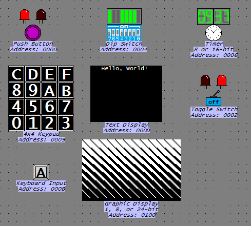
Once the outputs are pointed to a section of memory they automatically reflect any changes in that memory. To output something the program only has to write data in the section of memory mapped to that peripheral. Here is a list of outputs:
- LED
- 7 segment display
- LED bar
- Text output
- Graphic display (1, 8, or 24 bit)
This also allows outputs to be configured to do things that might be difficult to do in real hardware:
The inputs are also memory mapped and sync with the copy of memory the microcontroller has about 20 times per second. This is fast enough to type comfortably. Here are the inputs:
- Button
- Switch
- 8 position DIP switch
- 4x4 keypad
- Keyboard
- Timer
The timer can be set to regularly update and write its value anywhere in memory. It can work in 8 or 16 bit mode. This is useful for things like blinking a cursor that don't depend directly on execution speed.
To test my setup I started working on a four function RPN calculator with a 10 level stack. It can repeat keystrokes to implement functions like converting from Fahrenheit to Celsius, which you can see below. These functions can also be graphed which you can see on the graphical display in the program. The buttons and selectors are for selecting functions and graphing.
 Erik Piehl
 ErwinM