Close
0%
0%

Path Lighting for Walker

A lighting rig that attaches to walkers to assist users to see where they are going in the dark.

Similar projects worth following
A friend of mine uses a walker to get around his home. One time when I was visiting him I noticed that he would hold his iPhone up to use the screen illumination as a night light to see ahead of him in a dark hallway. That seemed less than ideal, as since he already needs a walker to get around, he's now also compromising his hold on one of the grips to hold the phone up.

I realized that I could make him something much better just using stuff I had left over from various movie projects and other things I had around my shop, so I got to work to build him a more useful solution to his problem.

I wanted to make this more than just a flashlight attached to a walker. When I searched to see what already existed to solve this problem, I found this:

http://www.parentgiving.com/shop/light-go-mobility-light-5368/p/

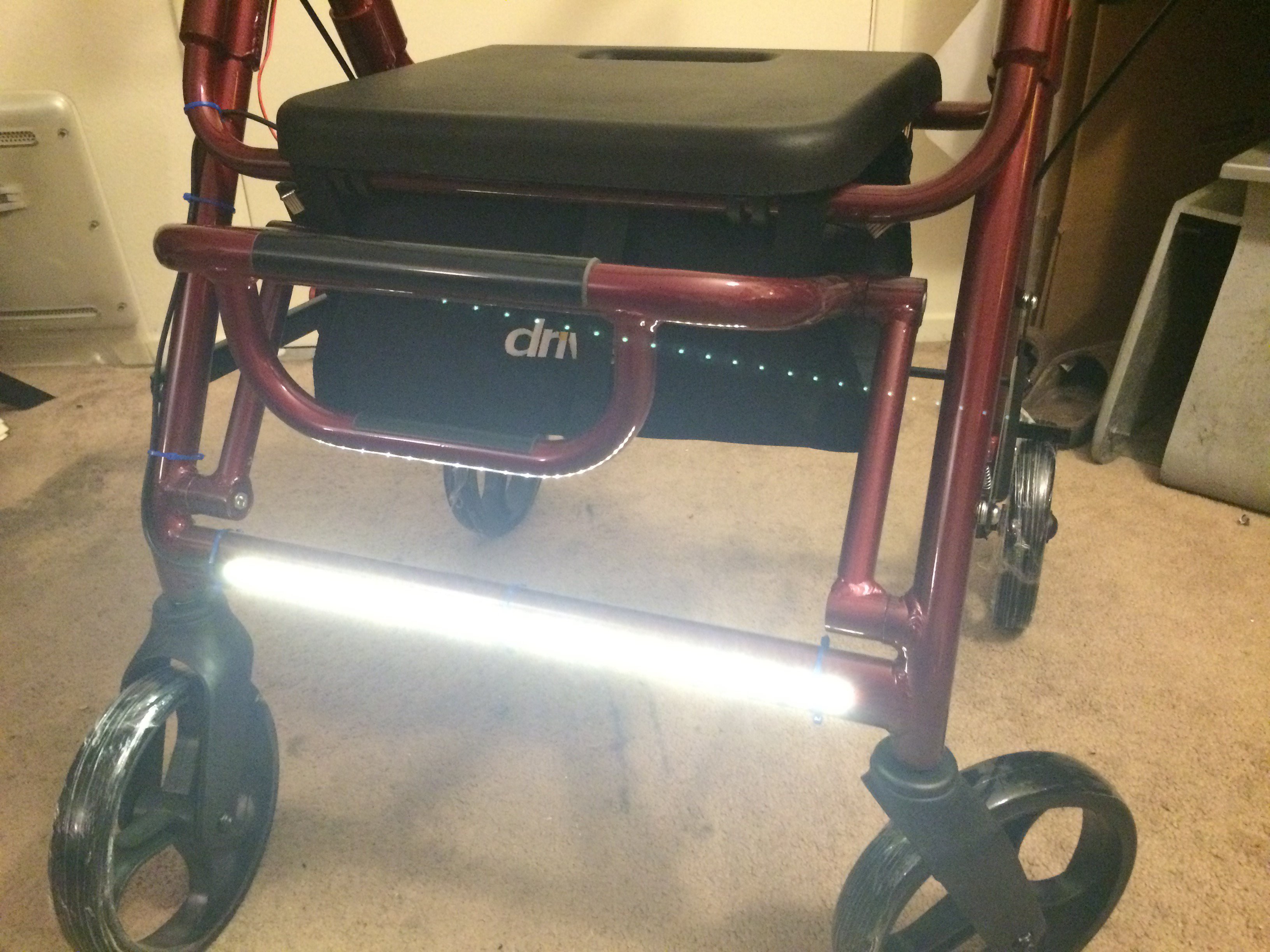
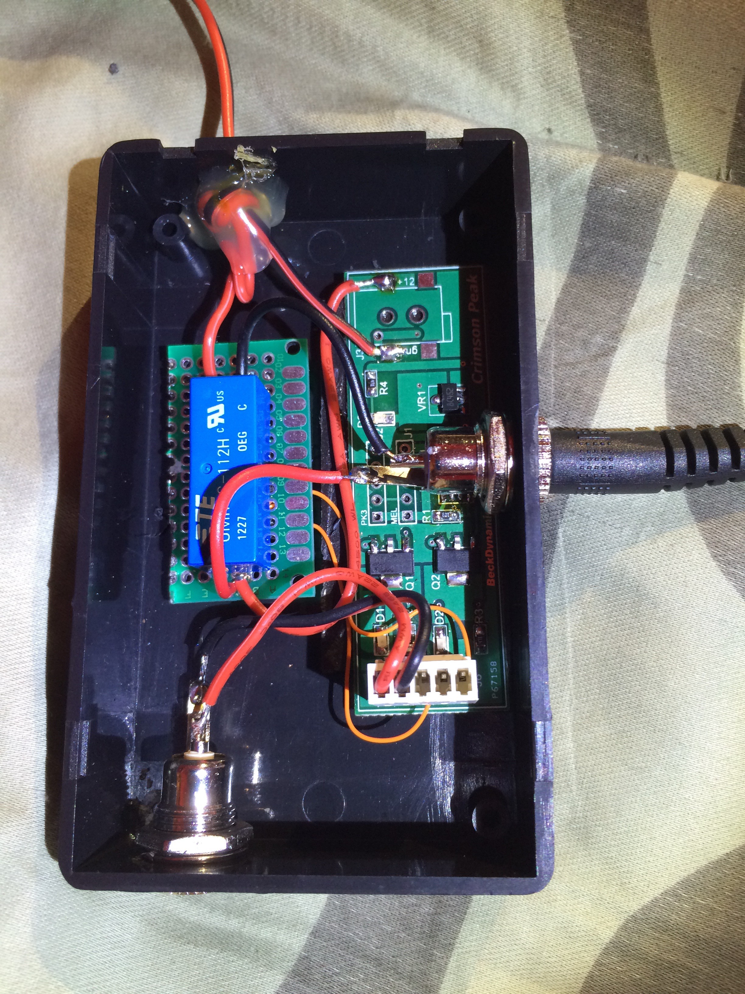
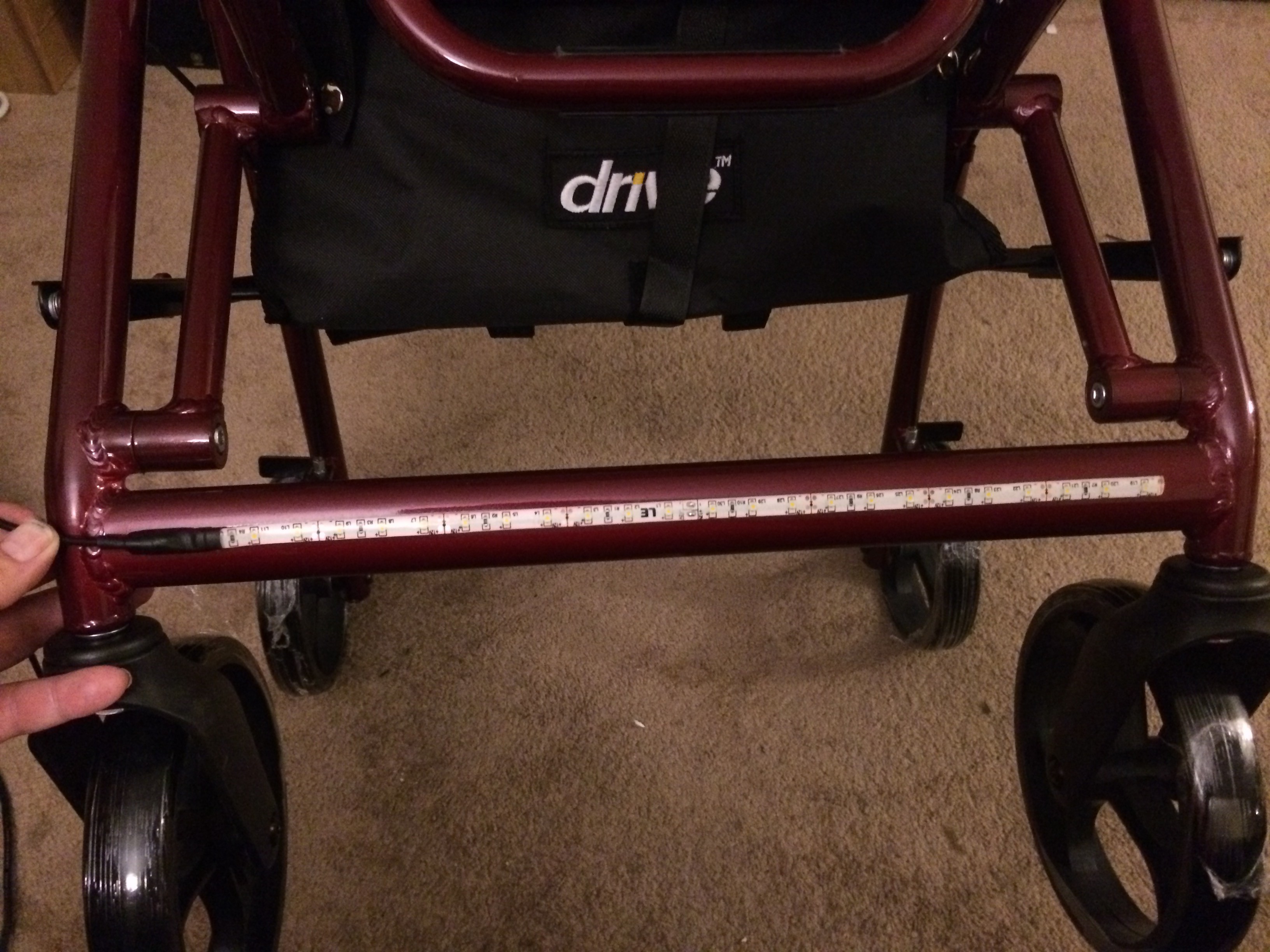
It is intended for walkers, but it is little more than a flashlight even though it features motion activation. What I wanted for this was more of an area light to illuminate the floor and hallway in front of him. Also I wanted it to be activated by a button press on the handle when he needed it, and also to go off on its own. By going off on its own it would allow him time to get seated on the sofa or back into bed before the light shut off. Additionally, I figured that if it faded down slowly over a few seconds, that would give him warning that the light was shutting off rather than just leave him suddenly in the dark again. And of course he could hit the button again to keep the light on if he needed more time to get somewhere.

  • 1 × PIC12F1501 Microprocessors, Microcontrollers, DSPs / ARM, RISC-Based Microcontrollers
  • 1 × pushbutton switch
  • 1 × Rechargeable LiIon Battery Pack
  • 1 × 12V LED tape, warm white, waterproof
  • 1 × 75L05 voltage regulator

View all 8 components

  • Part the Schematic

    scubabear08/17/2015 at 18:36 0 comments

    The electronics could hardly be an simpler; I used a board from a previous project and modded it slightly as described in the earlier logs. Here is the effective schematic:

    This board has two programming headers because this PCB needed to be able to be programmed from either the PICKIT3 or MELABs' own programmer. It complicates the visual of the schematic a bit, but it sure helped when initially programming the boards for the movie project that I made them for originally.

  • Part the Code

    scubabear08/17/2015 at 18:31 0 comments

    Way back on Star Trek: First Contact I started using Microengineering Labs PICBASIC PRO compiler. I used PICBASIC to write the code for the Borg suits and the spacesuit lighting in that film... That was 19 years ago, and I still use it for simple projects because it is very fast for me to develop in. Here is the very simple program to operate the lighting here:

    'written for PICBASICPRO V3
    'author Alan McFarland
    'August 16, 2015
    'simple program to operate lighting for Harlan's walker
    'uses PIC12F1501
    
    DEFINE OSC 16		'define the clock speed so PICBASIC knows
    OSCCON = $FF		'set speed to 16MHz
    
    '******************************************************************************
    '  SETUP 
    '******************************************************************************	
    	
    	ADCON1 = %00001111			'port a is all digital IO 
        tape    con 3				'output pin to LED tape
        relay	var porta.2			'output port to control relay 
        pwmrate con 20000			'pwm freq
        faderate con 10				'delay in PWM loop to control duration of rate change
        level   var byte     
    	count0          var word  
        
    begin:
    high relay				'as soon as the µC wakes up, turn on the relay to latch the power
    hpwm tape,0, pwmrate
    pause 250				'let settle
        
    trigger:
    for count0 = 0 to 255
        gosub fetch					'read in the sine value from the lookup table   
        hpwm tape,level, pwmrate	'send to hardware PWM & fade up to full
        pause faderate
    next
    
    for count0 = 1 to 50			'with a 2.3 second nap, this keeps light on for 115 sec
        NAP 7      ;nap for 2.3 seconds
    next
    
    for count0 = 0 to 255
        gosub fetch					'read in the sine value from the lookup table
        hpwm tape, 255 - level, pwmrate	'reverse the value since we are fading down
        pause faderate + 20				'make it longer to provide notice that its shutting off
    next
    
    low relay	'this will turn off power to the board
    
    END 
           
    fetch:
        lookup count0,[0,0,0,0,0,0,0,1,1,1,1,1,2,2,2,2,3,_
        3,3,4,4,4,5,5,6,6,7,7,8,8,9,9,10,11,11,12,13,13,14,15,16,16,_
        17,18,19,20,20,21,22,23,24,25,26,27,28,29,30,31,32,33,34,35,36,37,38,39,40,_
        42,43,44,45,46,48,49,50,51,53,54,55,56,58,59,60,62,63,64,66,67,69,70,71,73,_
        74,76,77,79,80,81,83,84,86,87,89,90,92,93,95,96,98,99,101,103,104,106,107,109,110,_
        112,113,115,117,118,120,121,123,124,126,128,_
        128,129,131,132,134,135,137,138,140,142,143,145,146,148,149,151,152,154,156,157,159,160,162,163,165,_
        166,168,169,171,172,174,175,176,178,179,181,182,184,185,186,188,189,191,192,193,195,196,197,199,200,_
        201,202,204,205,206,207,209,210,211,212,213,215,216,217,218,219,220,221,222,223,224,225,226,227,228,_
        229,230,231,232,233,234,235,235,236,237,238,239,239,240,241,242,242,243,244,244,245,246,246,247,247,_
        248,248,249,249,250,250,251,251,251,252,252,252,253,253,253,253,254,254,254,254,254,255,255,255,255,_
        255,255,255], level
        return
    

  • Part the Fifth

    scubabear08/17/2015 at 11:02 0 comments

    And here's the finished piece:

    And lastly, my curious pussycat looks on to see what I've been up to this past weekend...

  • Part the Fourth

    scubabear08/17/2015 at 10:56 0 comments

    I also wanted to use jacks everywhere so it could be easily removed and serviced if necessary. I hard-wired the power plug (red/black wire with hot glue strain relief) that would connect to the battery pack, and used two jacks for the LED tape feed and the switch connection:

    Although both of the jacks appear to be the same, the LED tape one is 2.5mm center and the switch is 2.1mm center, so they cannot be mistakenly interchanged.

    The power pack and the project box I used were exactly the same size. Some thin Velcro holds the two boxes together.

    And all the works conveniently fit inside the walker's utility pouch: battery pack, lighting controller, and battery charger:

    All that was left was to make the button. Again I used some heat shrink to protect the wire & connection, and attached it up by the right side handgrip:

  • Part the Third

    scubabear08/17/2015 at 10:45 0 comments

    Amazon has a 12V lithium ion battery pack I'd used on other projects before; it comes with a charger and the price ($24) is pretty decent to get it next day. (Aliexpress has better pricing, but it can take weeks to get stuff from China).

    For this application though, the battery pack required a bit of hacking. First off, there's a switch on the battery pack that must be on for the unit to operate, and that switch must also be in the on position to charge it. Not intuitive, in my opinion. It also has a battery gauge that reads out the charge level.

    That LED level indicator is handy, but it is on all the time the battery pack is on. That would drain the battery pretty quick. So I opened up the pack, wired the rocker switch out of the circuit, and put the charge indicator on a momentary switch so it could be used to gauge the charge only when someone is actually looking to check the level.

    Switch bypassed and momentary switch installed:

    Reassembled:

  • Part the Second

    scubabear08/17/2015 at 10:31 0 comments

    Next up was the LED tape selection. I wanted to use waterproof tape, because I learned from building the LED lightsuit for Dr Manhattan on the Watchmen movie that unprotected LED strip is easily damaged. Waterproof LED tape wasn't available back in 2007 when we did that movie (back then blue LED tape was over $100 a roll!), but silicone-sealed LED tape is easily available from Amazon, and I had a partial reel of it left over from something I did for The Magic Castle a few years ago:

    I cut a piece to the proper length to fit the front bar of the walker, and then stripped away the silicone an inch in so I could solder the wires onto it (a rosin flux pen is invaluable for this!) and then heat shrink the whole thing to protect the junction.

    Tape with silicone cut away:

    Wires soldered:

    Heat shrinked:

    And installed on the walker's front bar:

  • Part the First

    scubabear08/17/2015 at 10:19 0 comments

    I've made hundreds of circuit boards over the past 27 years for electronics special effects movies over the years, so I figured I probably had something that would work. I wanted essentially a timer with a MOSFET to switch 12V through PWM. I had recently finished something for a movie coming out later in 2015 and I had a bunch of PCBs left over form it, and I realized I could use one of these little boards with almost no modification.

    This board has two MOSFET outputs for two different LED control channels. One of my design goals for this was to have the battery last as long as possible without recharging, but since I was using 12V LED strip and a 5V PIC processor, sleeping the processor wouldn't be good enough as the 5V regulator would always draw some current.

    The solution I came up with was to use one output for the LED tape, and use the other output to switch a relay to open the circuit from the battery pack completely. Then all the pushbutton switch would have to do is close the circuit across the relay contact--the µC would activate, turn on the relay coil, and then the pushbutton switch could be released. The µC would fade up the LEDs, time their on duration, fade the LEDs off, and then turn off the relay coil to save the battery. This approach worked really well, and the reed relay coil only draws a mere 11mA.

View all 7 project logs

Enjoy this project?

Share

Discussions

Similar Projects

Does this project spark your interest?

Become a member to follow this project and never miss any updates