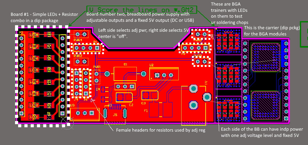
Tthere are 6 boards here that are V-scored to break away. Left side is simple dip package module with some LEDs to get your feet wet soldering. the center board is a power supply for the breadboard and the right-most two columns incl. 3x BGA-PCBs (a pcb with BGA pads on the bottom) and a PCB that carries two of these 3 smaller modules.


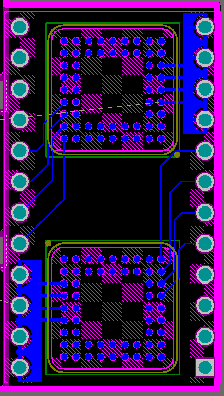
Lastly is the carrier for the BGA parts. This is just landing areas for the BGA-PCBs and a breakout to a standard DIP package for the breadboard. It's a useful way to connect boards together when the boards are small enough (so warping doesn't kill it) and there is enough room on the child-board to be able to encapsulate some capability.
 technolomaniac


 danjovic
 The Big One
 Charlie
 Anool Mahidharia
ooh, for sure! I have a stickvise here so I think I just need the jaws, no?