 Lentin Joseph
Here is the book promo video which describe the Chefbot Project and the each chapters in the book
0%
0%
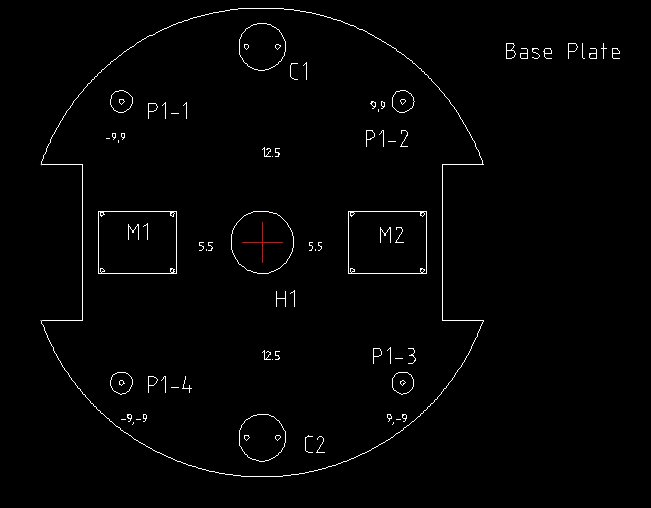
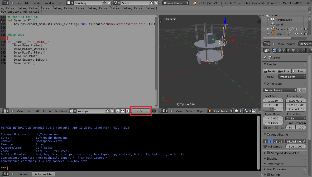
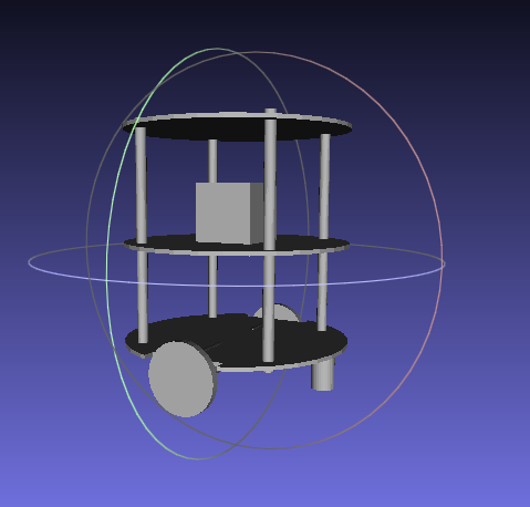
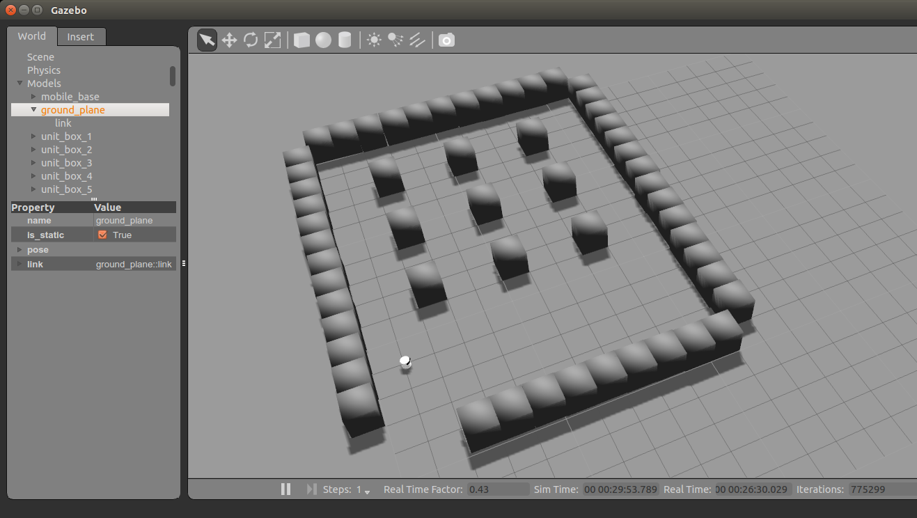
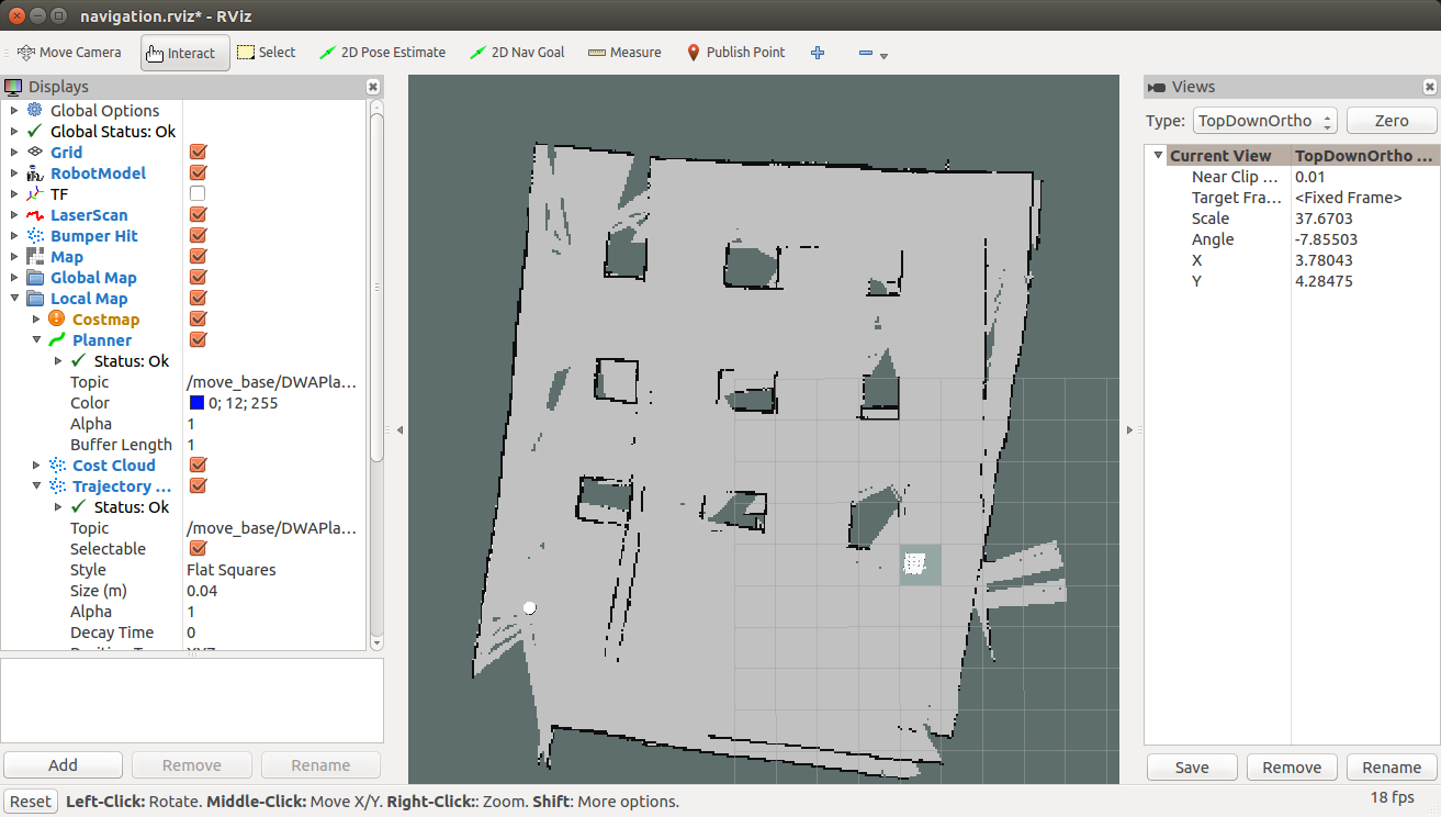
DIY Autonomous Mobile Robot
This project is about building an autonomous mobile robot with the help of Robot Operating System(R.O.S) and Python.
Become a Hackaday.io member
Already have an account? Log in.
Just one more thing
To make the experience fit your profile, pick a username and tell us what interests you.
Pick an awesome username
hackaday.io/
Your profile's URL: hackaday.io/username. Max 25 alphanumeric characters.
Pick a few interests
Projects that share your interests
People that share your interests


 Nikhil M Jeby

 Thomas Messerschmidt
 igorfonseca83