 Alex Rich
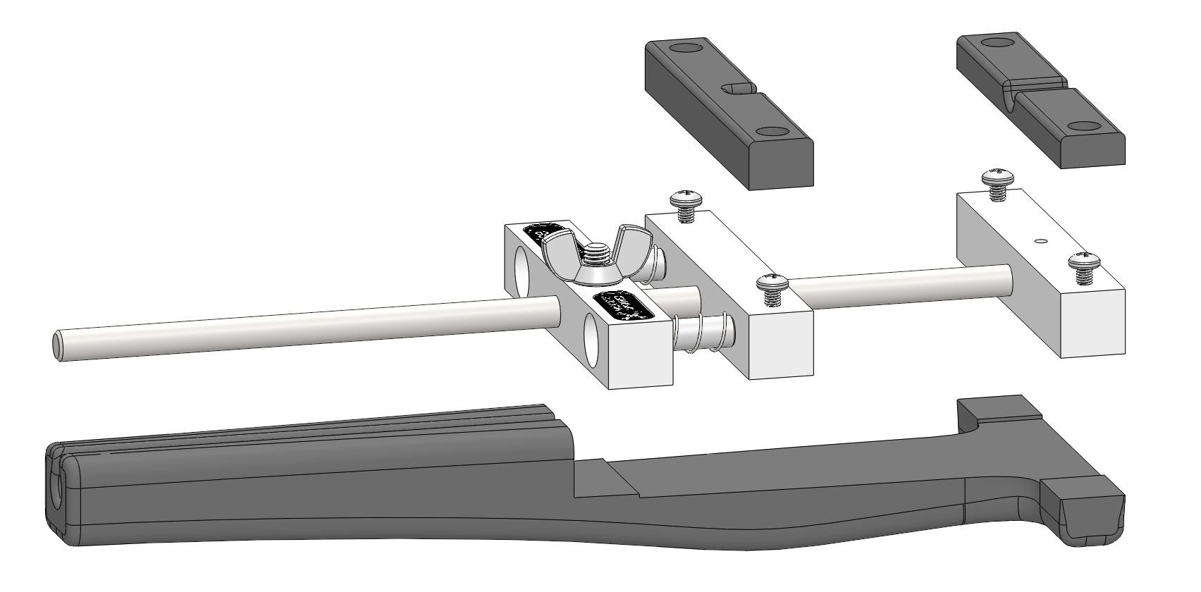
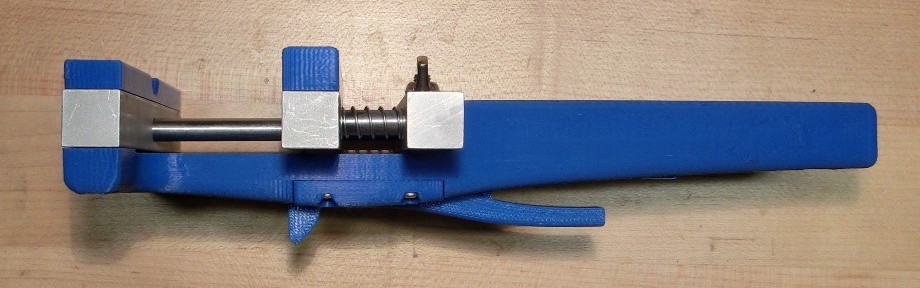
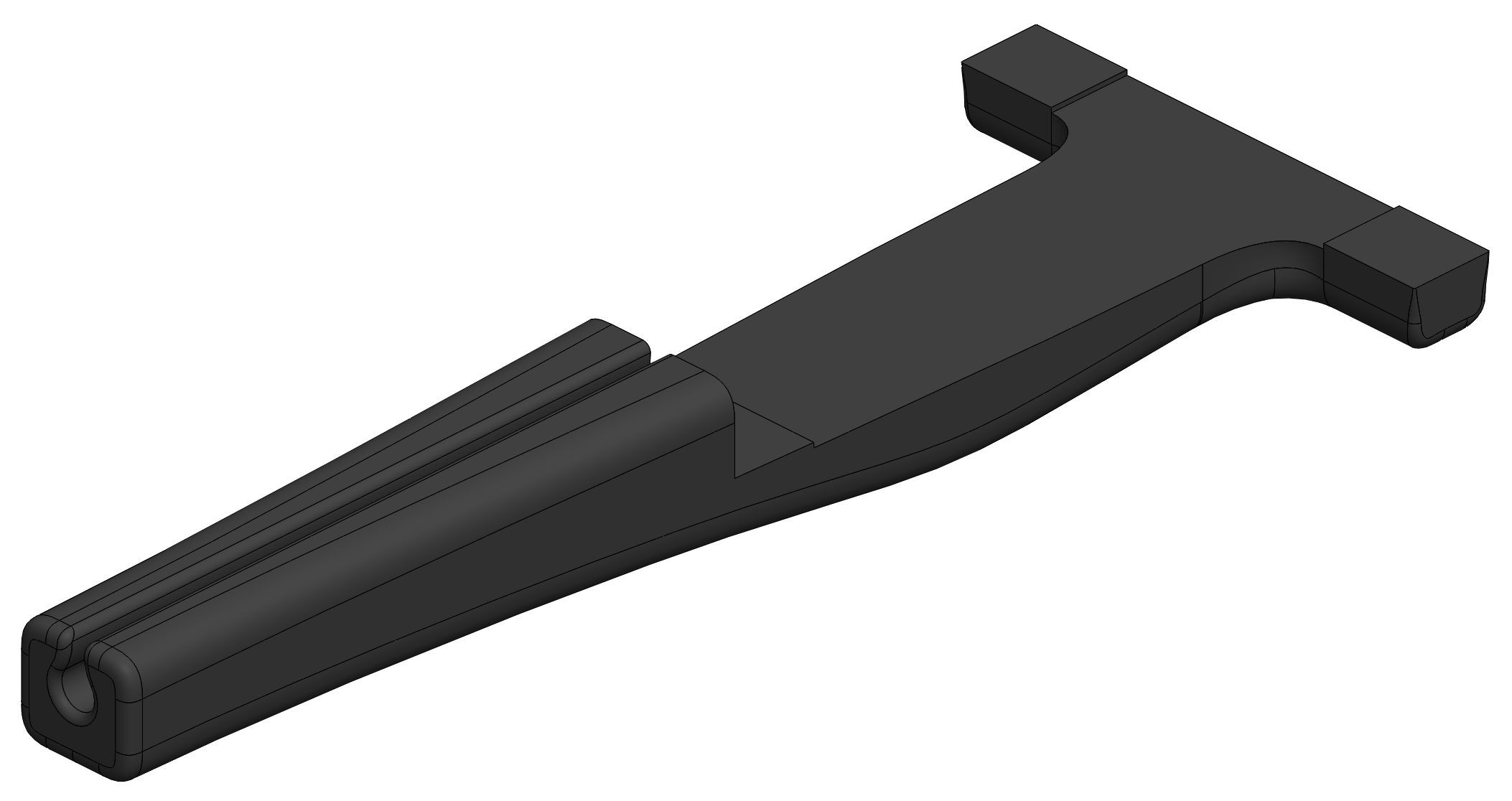
Current design includes handle as well as the jaw plates that will push / guide the projectile. All I need to do now is design the trigger parts.
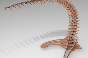
Every electronics bench should have a crossbow. First crossbow project on hackaday.io
Already have an account? Log in.
To make the experience fit your profile, pick a username and tell us what interests you.
Current design includes handle as well as the jaw plates that will push / guide the projectile. All I need to do now is design the trigger parts.
Stickvise_Crossbow_v1.zipV1 - this design doesn't shoot very far but it looks cool and the trigger works really well. Stay tuned for v2 which will take into account some of the things I learned in the physics analysis.application/x-zip-compressed - 2.49 MB - 12/20/2015 at 16:34 |
|
I was close to submitting this project to the tip line for fails of the week, but then I decided I had to try a bit harder to make it work. Here are the things I am fighting right now:
here are some ways to improve the situation:
This sounds self explanatory, just reduce the mass of the moving parts right? Wrong! The Stickvise movable jaw is not something I can easily change so I am going in the other direction -- I am going to try reducing the acceleration of the heavy parts. In other words, I want the movable jaw to gradually move forward never reaching a very high speed.
You might be wondering how this will increase projectile speed...
Well in my previous log, I showed that we are moving 58 grams of mass: 55 grams is in the movable jaw parts and only 3g is in the pencil! What happens if the jaw top speed approaches zero and I dump closer to 100% of the spring energy into the pencil?
This is easy to calculate using the conservation of energy equation again, but this time just use 3g (.003 kg) for the mass of the pencil (recall k = 2700 N/m and spring travel is 0.00948 m).
The previous velocity was 2 m/s so we have an increase of 350% if we use all the spring energy on the projectile rather than on the movable jaw parts. To do this I need to implement a clever mechanism to keep the heavy stuff moving slow and the projectile moving fast. Imagine stepping on a garden rake and having the long handle swing up and hit you in the face. That's what I want the movable jaw to do to the projectile.
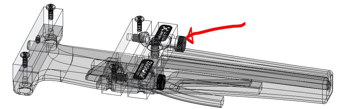
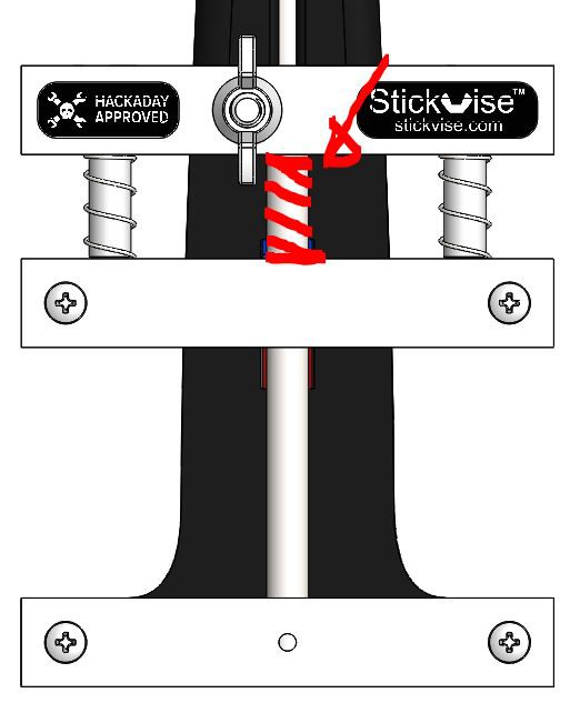
Spring travel is limited by the shoulder screws shown below, the current ones are 20mm long, McMaster sells longer ones so I am going to buy some 45mm shoulder screws for a couple bucks and see what that does. Of course this does add mass, but theoretically this won't hurt me if I can keep that mass from accelerating too much.
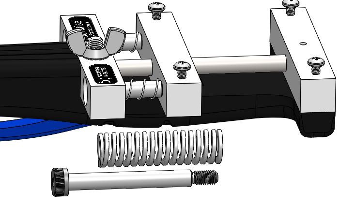
Stiffness goes at odds with spring travel, the longer a spring is the lower its spring constant is. To make sure this isn't a problem, I am going to order some ridiculous die springs with stiffness of 10,507 N/m (60 lbs/in) each for a total of 21,000 N/m in parallel. Of course these cut into my spring travel because they don't compress very far, but I think that tradeoff will work out ok. See below for a comparison of new springs with the standard Stickvise springs. They might break my trigger mechanism but that's ok, I'll cross that hurdle when I get there.
The final measure I am going to take if necessary is to add a third spring to the center shaft. This will bring the stiffness to 31,500 N/m which is 11.7 times the stiffness of the stock vise (2700 N/m)
Assume we have a clever mechanism that puts all energy into the projectile, and assume upgraded springs and spring travel, the velocity works out to:
This is 55.5 miles per hour, not bad! At this speed a projectile would travel over 29 meters horizontally before hitting the ground. Of course this is the upper limit, we'll see how it goes.
So the springs on Stickvise seem fairly strong, why does my velocity suck? I intentionally didn't do any analysis ahead of time because I just wanted to focus on the idea, not the results. Here I will do a quick grade school physics analysis to see why the pencil didn't go too fast or far.
First let's figure out what we will need to know to calculate projectile velocity:
1. How stiff is the spring (what is its spring constant, k)?
2. How much mass does the spring have to move (sum of moving vise parts mass + projectile mass)?
3. What is the travel (how far does the spring move the mass)?
To find a spring constant for my springs, I simply put a stickvise on a scale, tared it, then compressed the spring loaded jaw by a measurable amount and took a reading from the scale. Here's what I came up with:
1. Spring Constant Calc.
Spring compression: .214" (.00544 meters)
Scale reading: 1500 g (1.5 kg)
Note that the scale thinks it is weighing a mass in earth's gravitational field, so to get the actual spring force from the mass reading, I multiplied the mass (1.5 kg) by 9.81 m/s^2 to get a spring force of 14.715 N.
To get spring constant use Hooke's law for spring force (a good approximation I hope):
and solve for k:
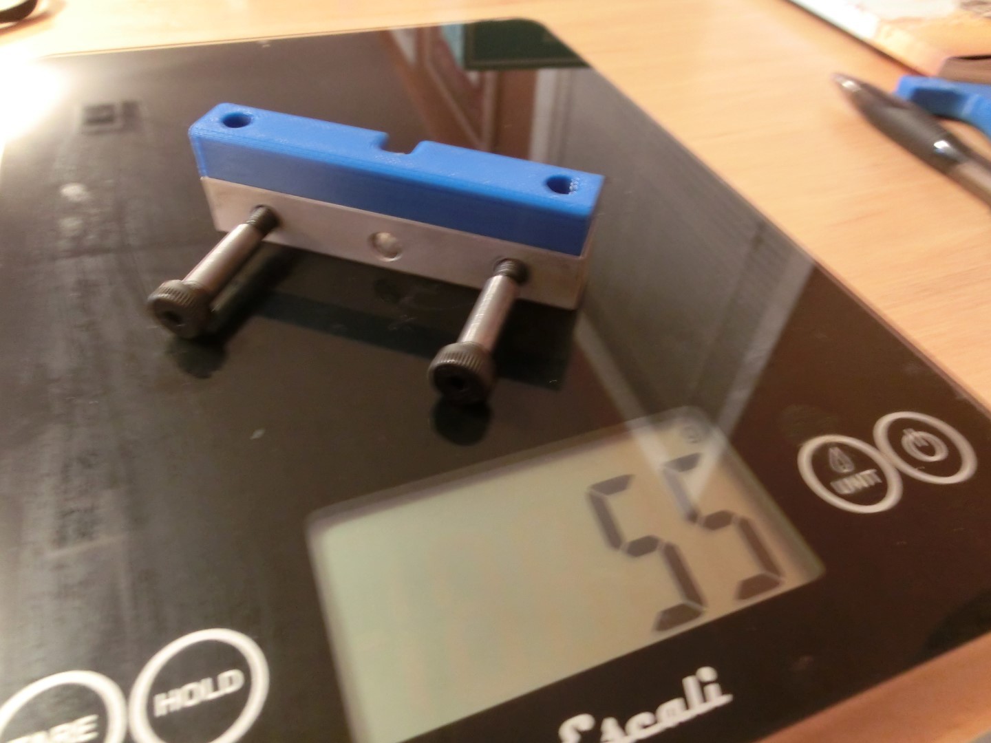
2. Mass the spring has to move
No calculation needed here, I just weighed the parts. It was 55 g for the vise parts, the pencil (not shown) was 3 g for a total of 58g (.058 kg)
3. Spring travel
For this I just measured the jaw spacing before and after cocking the trigger. The total travel is .373" or 0.00948 meters.
Calculating final velocity
Neglecting wind drag and friction, you can find the projectile velocity using conservation of energy equation shown below. The left side is the potential energy stored in the spring, the right side is the kinetic energy put into the moving parts.
solving for velocity you get
hmmm this is 4.57 miles per hour, not breaching the speed of sound any time soon.
When shot horizontally from a height of 1 m, the projectile will travel .926 meters before hitting the ground...
Well one interesting thing I got out of the calculations is that I am better off finding ways to increase the travel of the crossbow (x) rather than I am going to beefier springs or lighter weight on the moving parts. I guess I should probably do all three though because I am so far from an awesome crossbow right now.
Let me know if my calcs are off, the final results were close to what I saw in reality so I'm thinking they are probably correct.
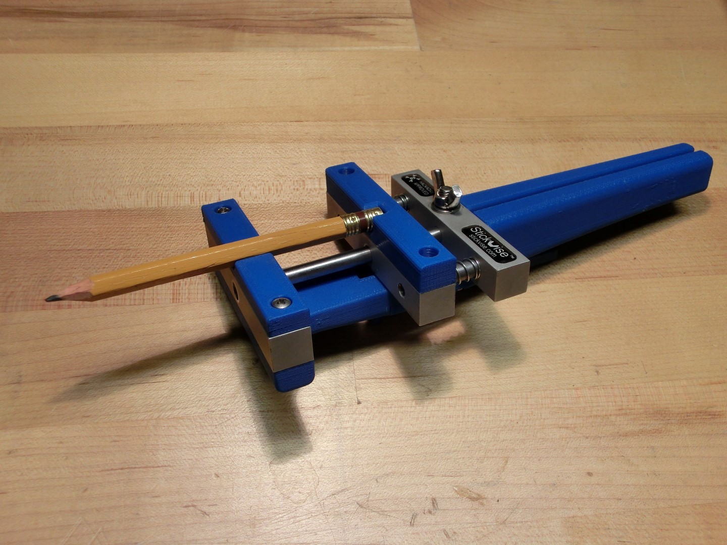
Ok we have a functioning prototype! Not exactly spectacular velocities, but it's a good start. Next step is to escalate this, any ideas appreciated.
Some photos of the finished prototype:
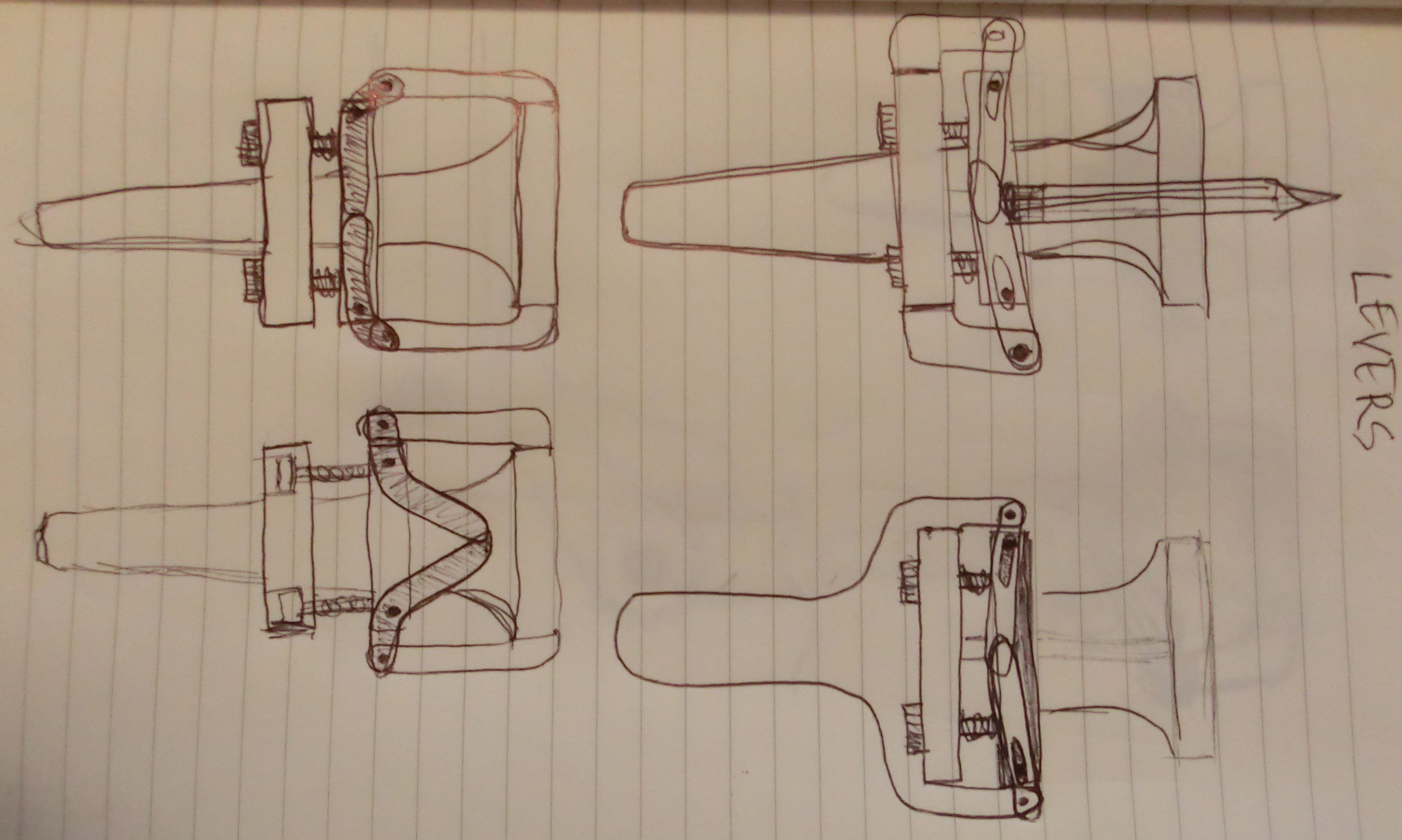
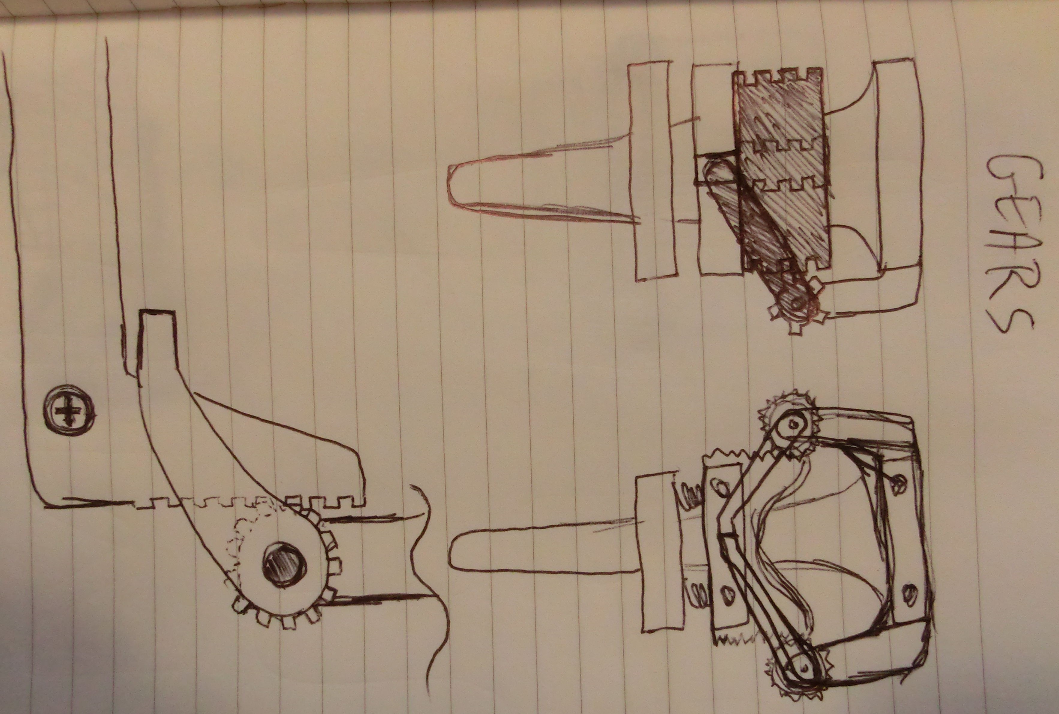
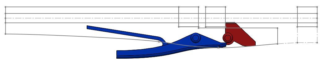
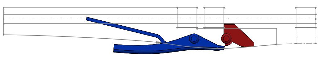
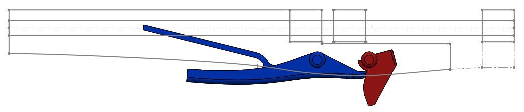
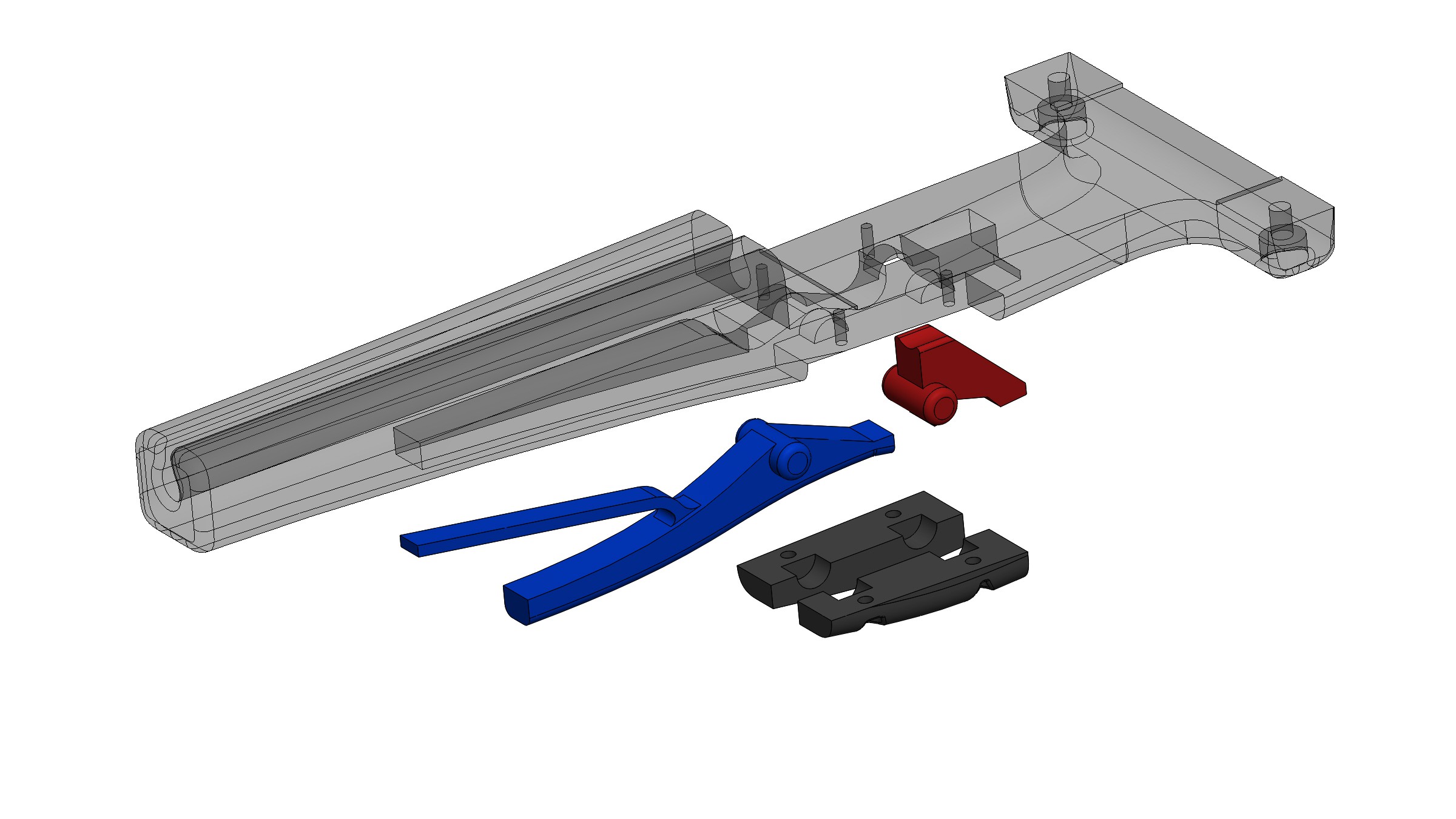
I tested the idea of a single trigger without a nut to keep things simple, but I realized the pivot of the trigger was below where the trigger latched, meaning it could slip off on its own potentially. To eliminate this I went back to the idea of using a nut. The nut has a built-in lever so that I can easily reset it after firing. Below is the CAD process.
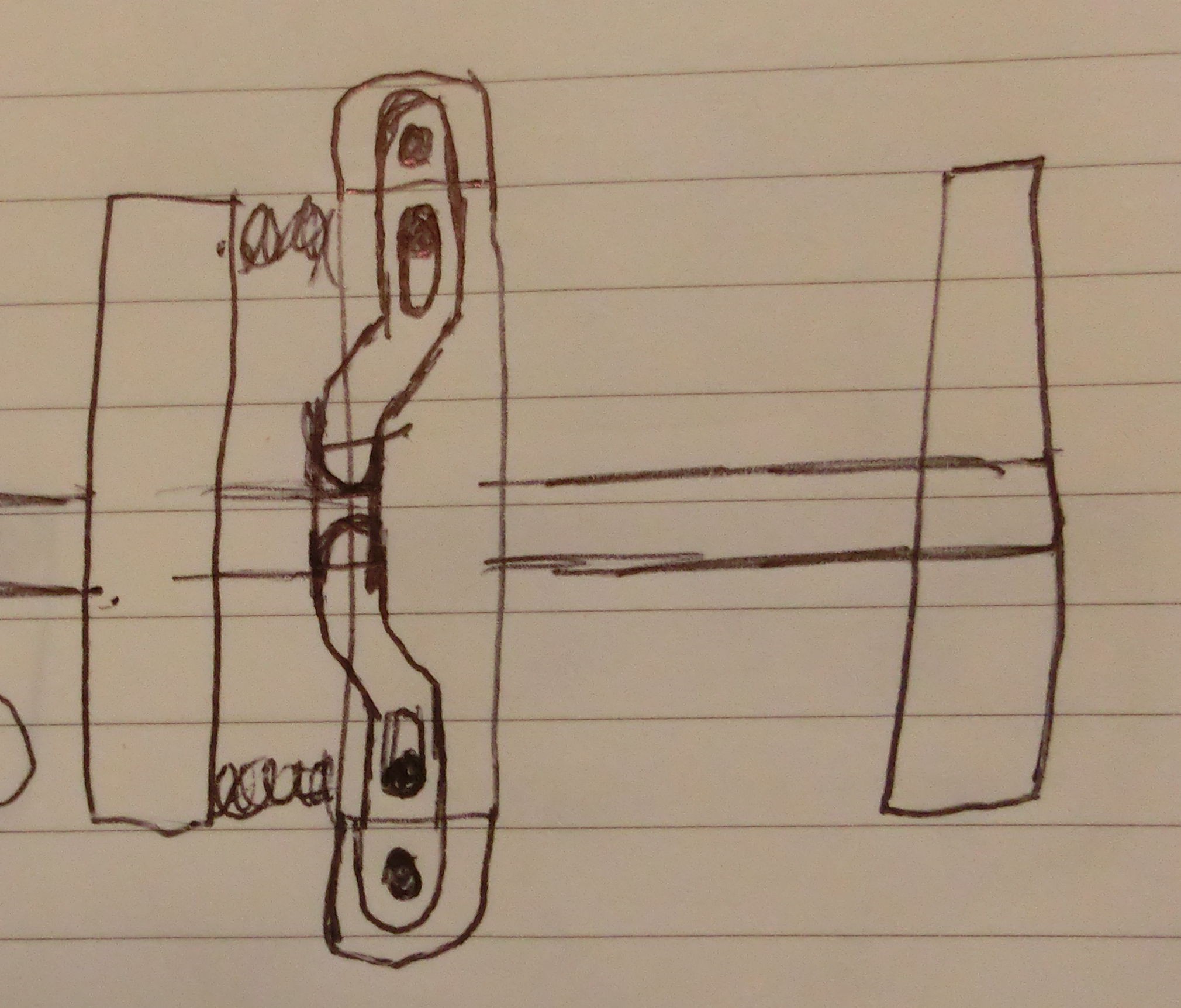
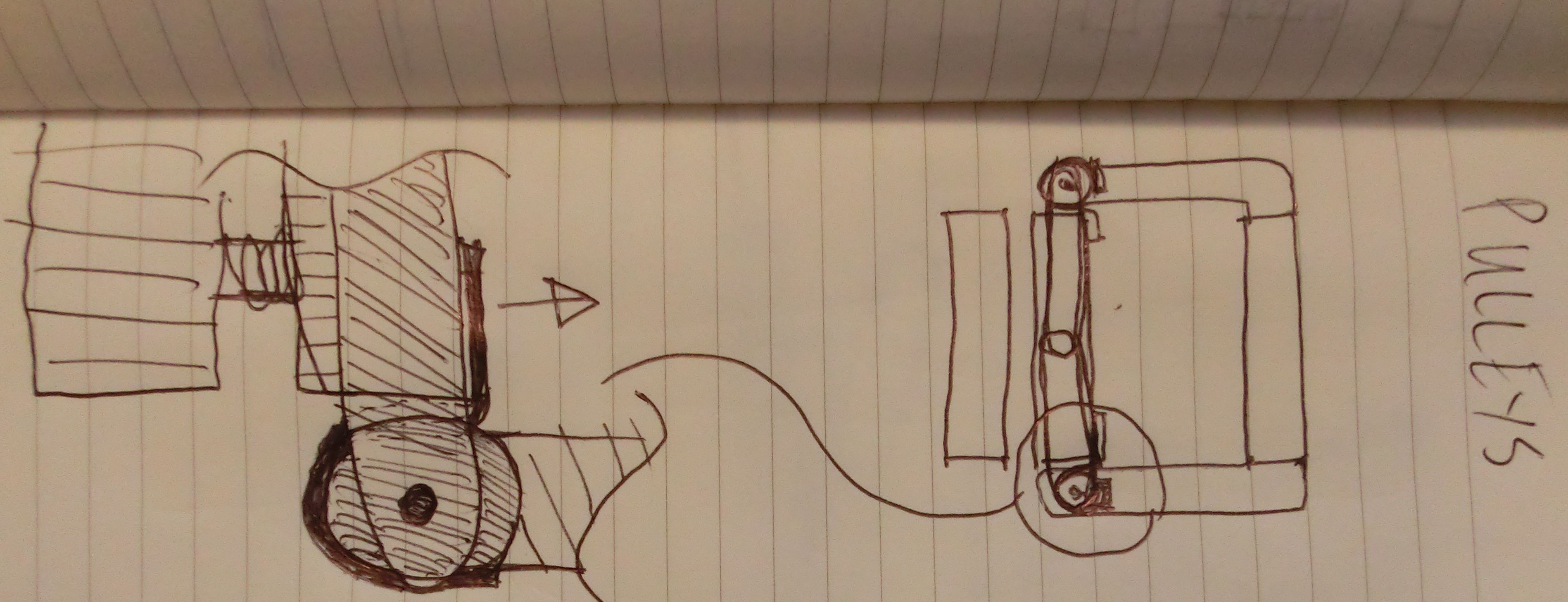
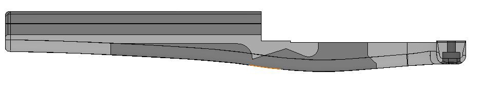
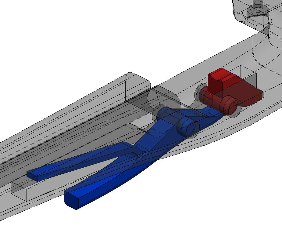
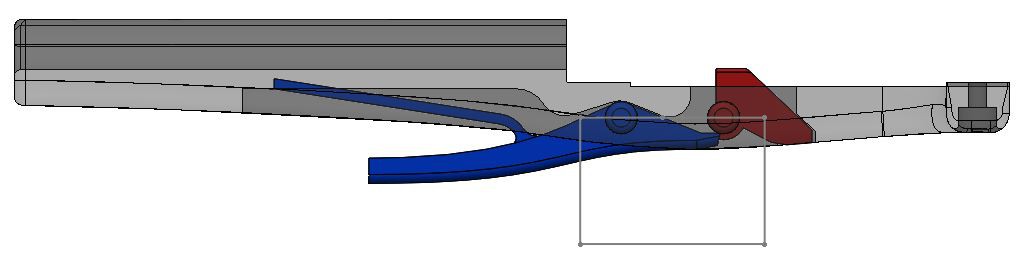
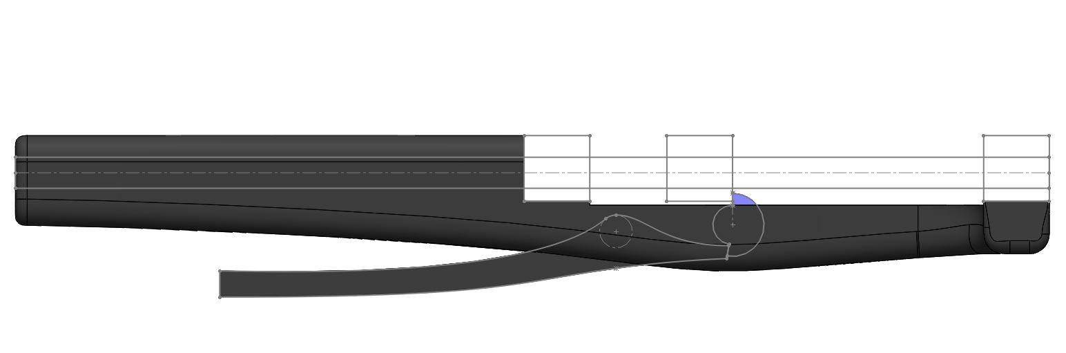
Step 1: Here is the side profile sketch I came up with after tinkering with it for a little bit.
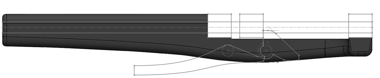
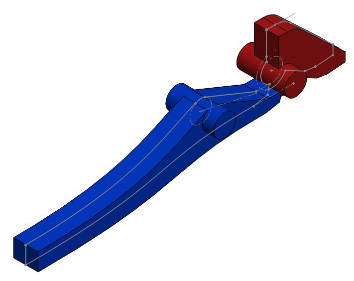
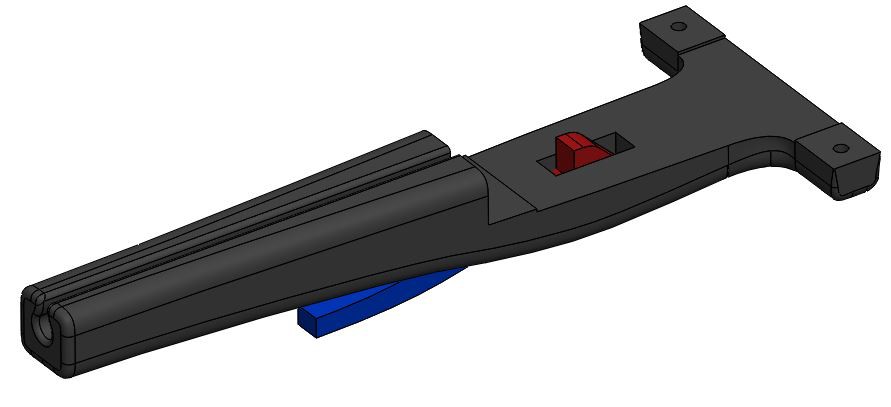
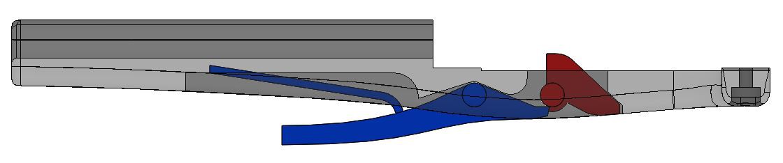
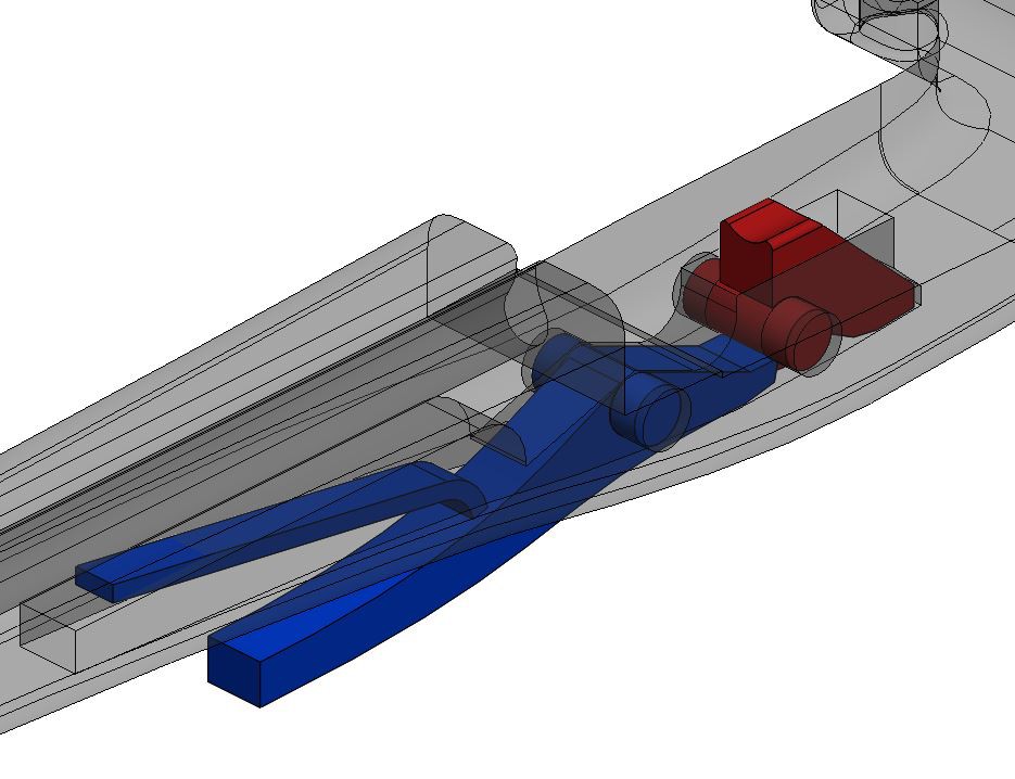
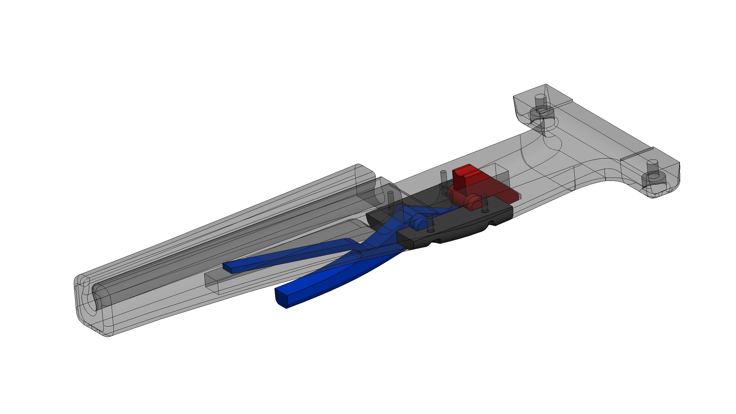
Step 2: Extrude the trigger (blue) and nut (red). Also extruded cylinders for the pivot points.
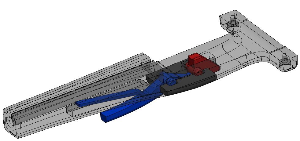
Step 4: Add a built-in return spring to the trigger, hopefully this won't just snap like a twig...
Step 5: Cut holes for the pins to rotate in
Step 6: Add fillets
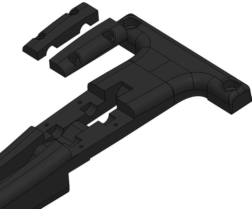
Step 7: In order to be able to assemble the trigger parts, I am going to split away two little pieces of the handle that will act as retaining plates. You can see the sketch and the finished split parts in the two pics below.
Research
The internet is the best. I found a nice write-up on crossbow trigger design that I'm going to try to follow:
http://crossbow.wikia.com/wiki/Designing_medieval_nut_and_trigger_crossbow_locks
The article details nut and trigger alignment, nut and stock alignment, etc. Amazing how minor differences in angles and pivot locations drastically change the function of the trigger.
Design
Here is my first stab at the trigger, side view. The main issue I see is how I will re-cock the trigger. On a normal crossbow, the string moves out of the way so you can reset the trigger, on Stickvise the trigger gets blocked by the movable jaw after firing. Hmm...
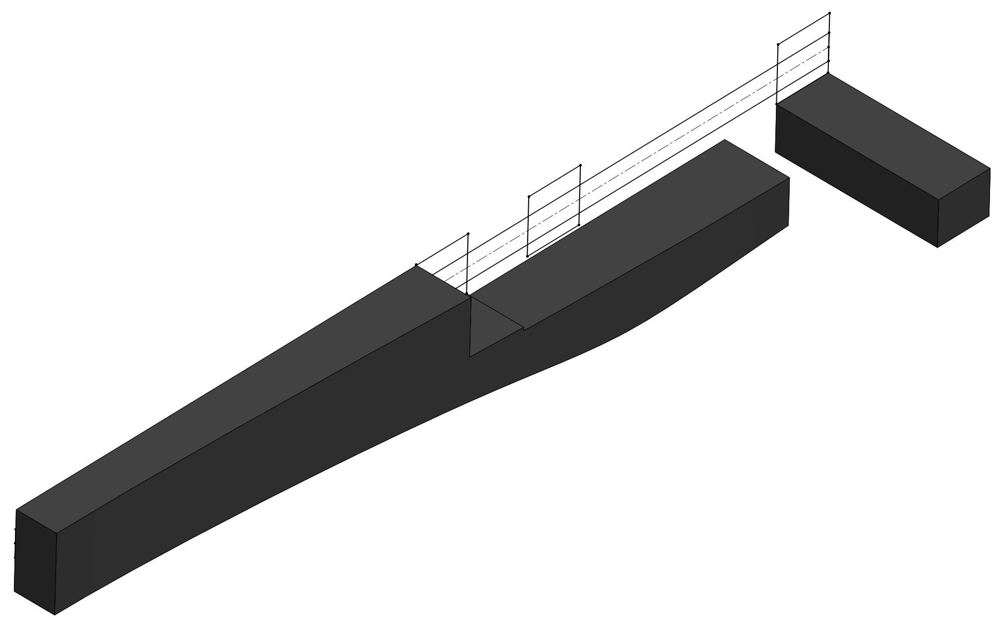
Here is a rundown of the steps I took in CAD to create the handle. You can get way fancier for sure, but sometimes I think using advanced features like lofts and sweeps ends up being uglier than simple clean linear extrudes.
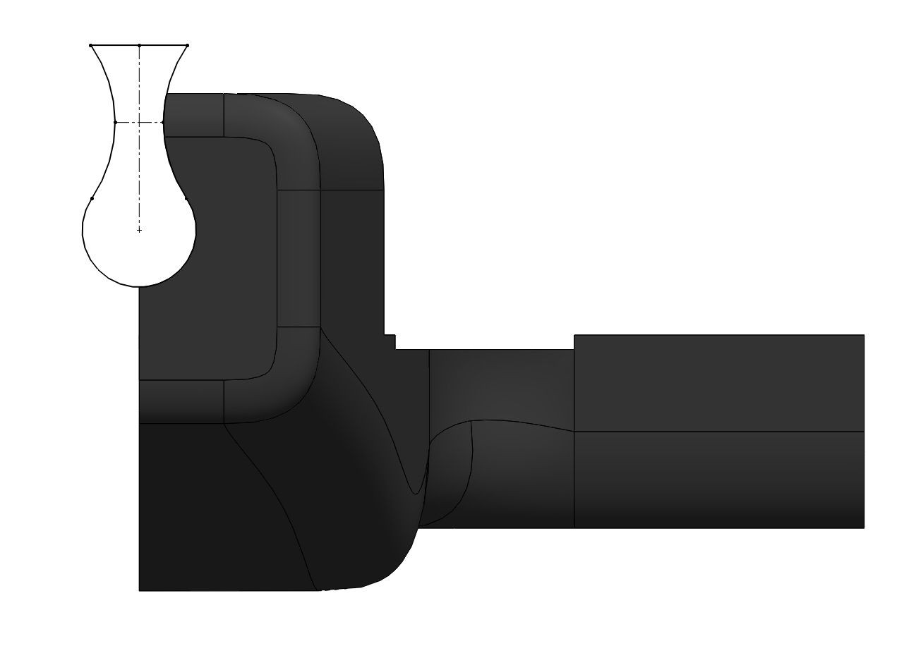
Step 1: Sketch side profile of stickvise in one sketch, then in a second sketch draw the handle shape. The handle shape is loosely based on my pen sketch, but really is just eyeballed.
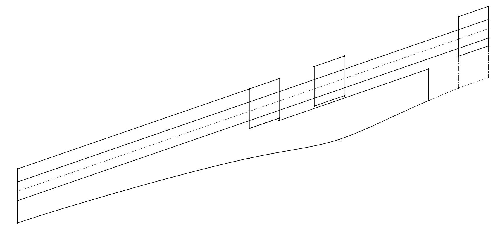
Step 2: extrude the handle shape in one direction. Since this will be a symmetrical handle, I will only create one side of it and then use a mirror feature at the very end to finish it.

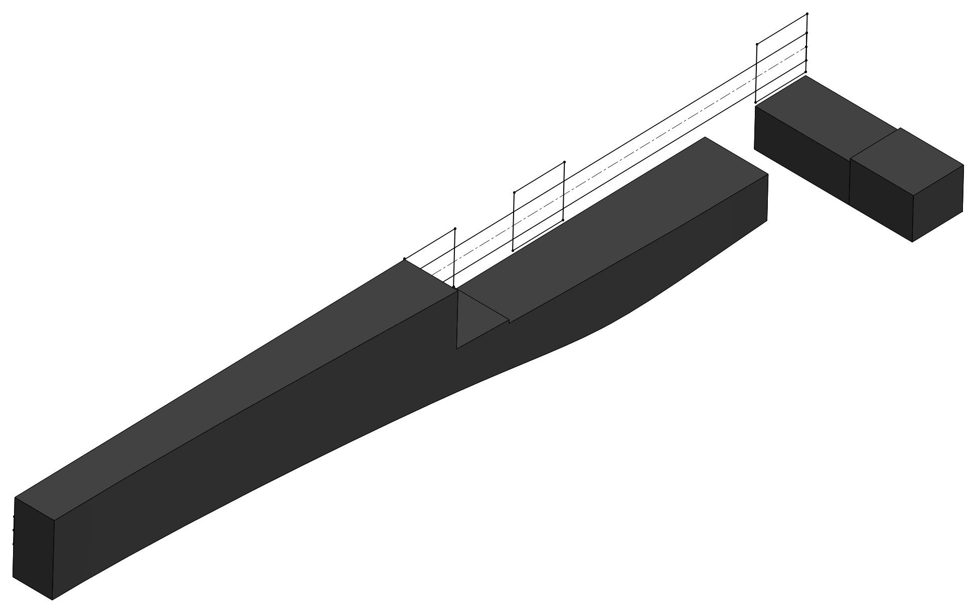
Step 3: Sketch the top profile of the handle and then cut extrude. This curve was also eyeballed, it is just a single spline that has a gentle curve to it.
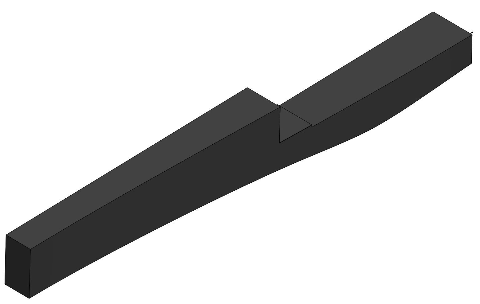
Step 4: Create the piece that will eventually attach to Stickvise's fixed jaw.
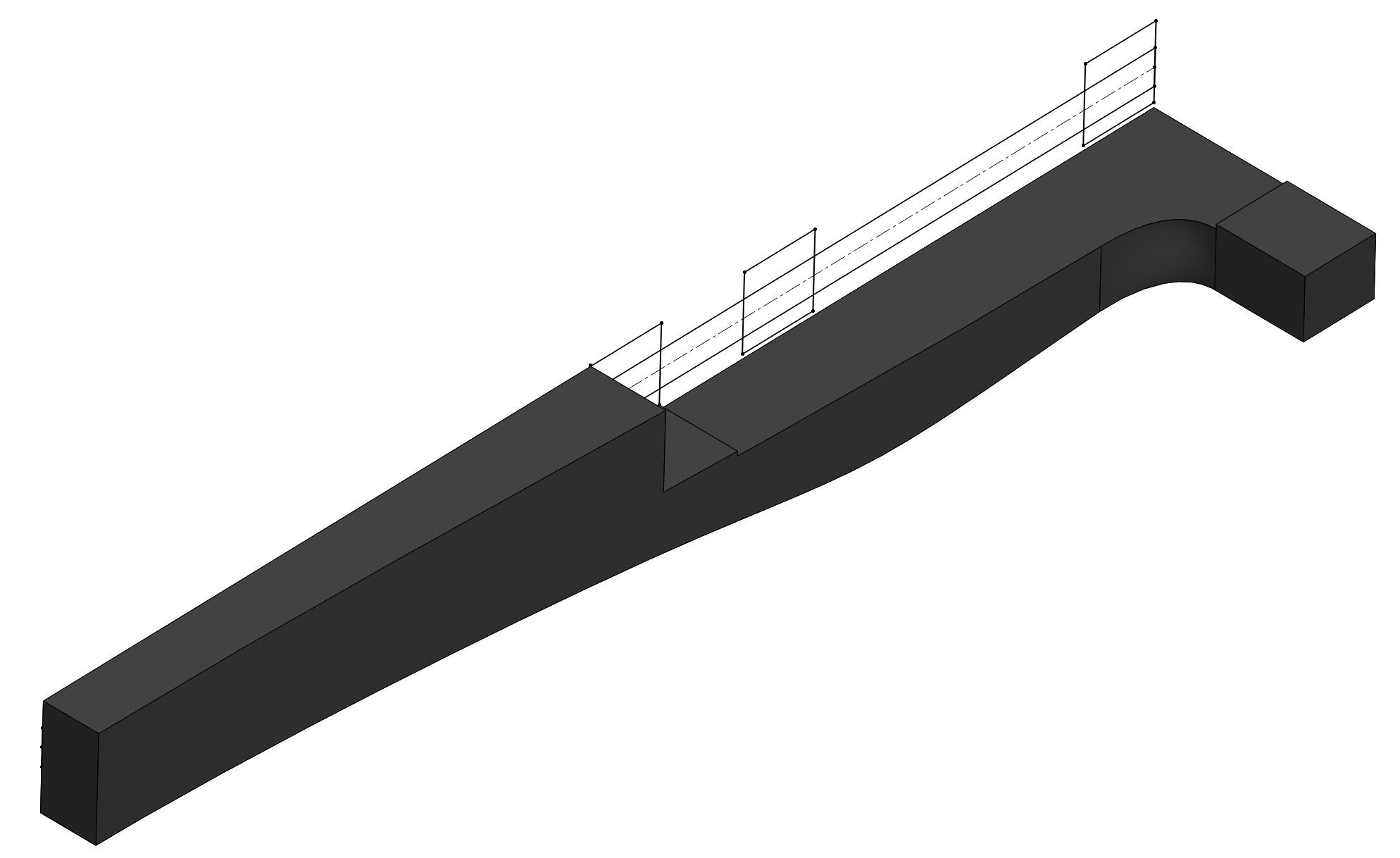
Step 5: This is a subtle thing, but I cut a section in the middle of the fixed jaw that is .03" deep. This will make more sense in the next step, I am basically creating an area to join the two pieces together using a loft. This is because the handle has .03" of clearance from the bottom of Stickvise so there is no rubbing when you fire the arrow.
Step 6: Loft the two pieces together. You can see the top surface is one continuous plane. If I had not made the cut in step 5 the top surface would have a small wave in it. No big deal either way, but I like keeping surfaces which are intended to be planar, planar (if that makes any sense).
Step 7: Fillet everything as desired. I used curvature continuous fillets, but for 3d printing you can't tell the difference anyway especially on small fillets like these. Circular fillets would look fine.
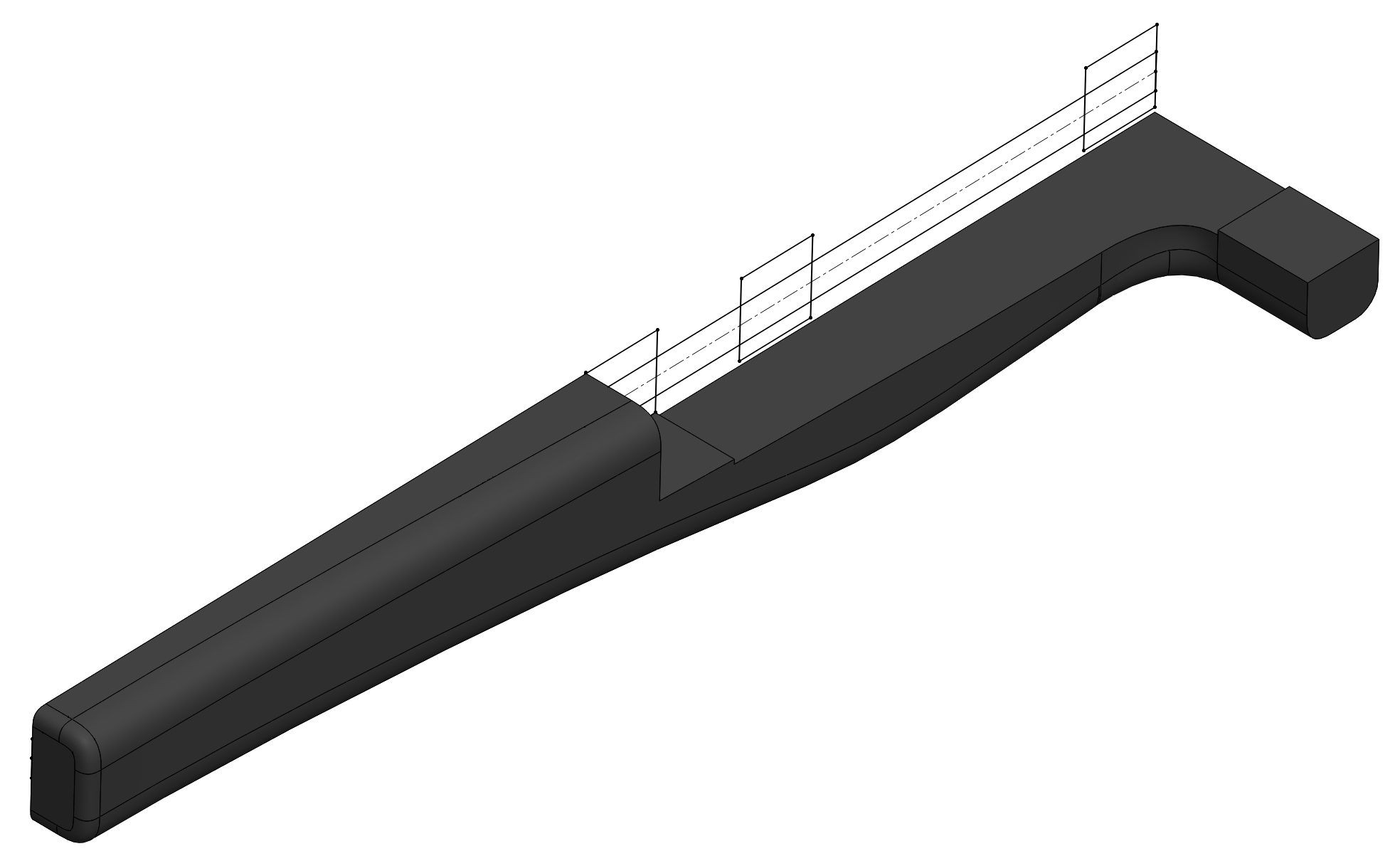
Step 8: Cut a hole for the shaft of Stickvise. The reason for the hourglass shape leading up is to prevent the need for support material in the 3d print while still capturing the shaft securely. I used a 1:1 fit which in my experience is fine for 3d prints because the plastic flexes a little bit. If necessary I can also ream this hole a bit with a drill bit to get the fit better in post processing.
Step 9: Mirror the body to form the final handle. This is the meat of the design, all that is left is adding mounting holes and a trigger. Will try to show the CAD process for that as well.
Thanks for providing us this great knowledge, I love the green space so visit https://totalsportektv.com/
i want to the complete file of this crossbow product. I'm working for the article of best compound bow that hosted on WordPress. <a href="https://techlarapoint.com/audible-mod-apk/">latest</a>
Sound good. I want to the complete file of this crossbow product. I'm working for the article of best compound bow that hosted on WordPress.

This project made me smile the moment I saw it i my feed :) I can't get my stickvise to shoot a pencil more than a meter or two, but I suspect with a nice trigger and fancy handle like yours to add whoosh this could be a fun little desk addition!

Hah thanks John! Yeah I don't expect too much velocity with the standard springs. This will escalate for sure, I think springs with longer travel would better simulate a real crossbow. I'm also not sure how much of an issue jamming will be, we'll see.
 Theoretical results:
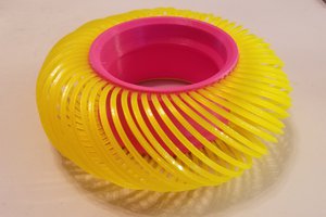
 Daren Schwenke
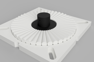

 David Troetschel
The Stickvise is a device used to hold electronic components or small circuit boards during soldering or other electronic work. It consists of two parallel, adjustable metal jaws that hold the component in place while leaving the operator's hands free to work on the component. <a href="https://gbwhatsapp.net/gb-whatsapp-pro-apk/">GBWhatsapp pro</a>