Maciej Witkowiak
-
Source code is now on Github
01/02/2016 at 01:27 • 0 commentsI have uploaded my local repository to Github. The source code for Mini Pro and Micro Pro firmware as well as Python kRPC interface is available there: https://github.com/ytmytm/ksp-gegi
Last time I wrote:
The tests revealed some flaws in the software that need to be fixed:
- I wait for virtual USB serial port to be ready and because of this the joystick simulation won't work until some software opens COM port on PC side. After that the port can be closed and it works fine
- during mounting process I exchanged RCS/SAS switches and LEDs, it's easier to fix this is software
- I didn't read the docs with full attention and I pass values -127 to 127 as X/Y/Z axis rotation instead of 0-359 degrees
- I need to have a "status report" command so that modules report status of all potentiometers and switches on request, not only when they change
All these issues have been fixed.
I did some extensive testing of joysticks today using MAME. All works well.
-
Prototype Mark Two
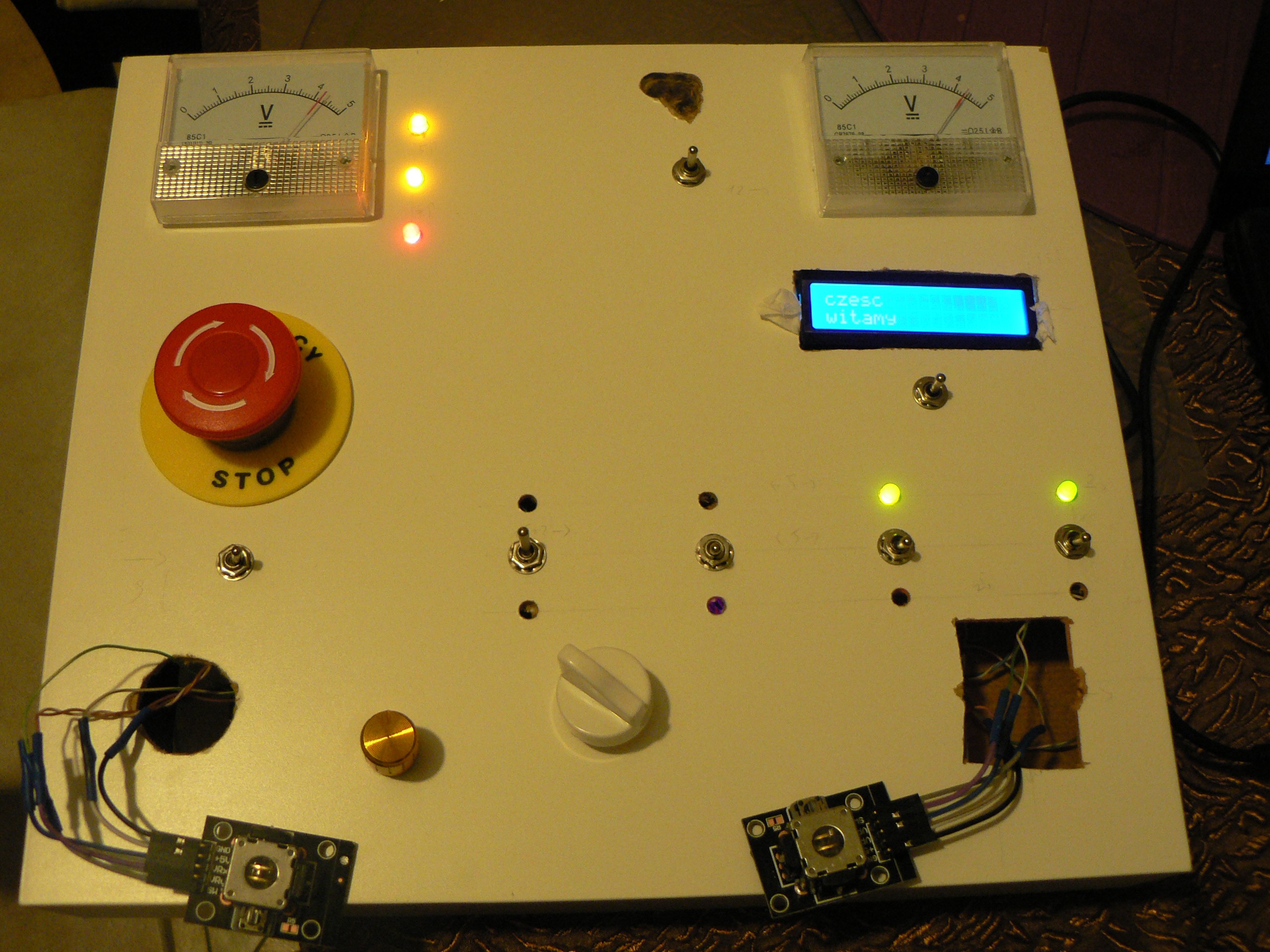
12/31/2015 at 13:25 • 0 commentsThe second prototype is ready. I still have only a vague idea how to mount OLED display and joysticks. At the moment they are fastened with brass M3 screws.
![]()
I have also made small notches on the back side so that potentiometers and switches won't rotate.
I decided not to use thumb knobs that came with the joysticks. I drilled 2mm holes in wooden pegs and I put them on the joysticks' shafts. This way I have better control and precision over the joystick movement.
The tests revealed some flaws in the software that need to be fixed:
- I wait for virtual USB serial port to be ready and because of this the joystick simulation won't work until some software opens COM port on PC side. After that the port can be closed and it works fine
- during mounting process I exchanged RCS/SAS switches and LEDs, it's easier to fix this is software
- I didn't read the docs with full attention and I pass values -127 to 127 as X/Y/Z axis rotation instead of 0-359 degrees
- I need to have a "status report" command so that modules report status of all potentiometers and switches on request, not only when they change
The hardware needs some further work too:
- I need to change the scale of analog voltmeters from 0-5V into 0-100% power and 0-5G force
- I have to add remaining 4 red and 2 green LEDs
- someone on Kerbal forums had a nice idea to add flicker whenever power level is low, this doubles the function of LOW POWER indicator, but may be a nice touch
- how to nicely mount joysticks?
- how to nicely mount OLED display?
- how to make labels?
- should I keep the panel white and just print them on paper?
- should I spray-paint the panel silver or gray? But then - how to make labels? I can't just print them on paper anymore
- maybe I should order a whole 20x30cm panel printed on adhesive foil
Of course I also have to rewrite Python interface between serial commands coming out of the panel and kRPC.
-
Soldering is complete
12/31/2015 at 12:08 • 0 commentsThis is also a backlog entry. I did soldering over two evenings: 28th and 29th December. I have no experience with preparing boards for manufacturing so I went with a plain perforated board with 18x24 holes. What's worse, I didn't have proper connectors and I decided to solder all the wires directly to the board.
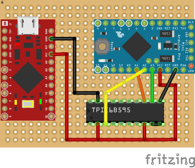
I used Fritzing to have a general idea how to layout components, which connections must be done close to be board and how to make enough room for external wires.
![]()
I tried to be smart and wanted to hack precision sockets to mount both Arduino boards for easy replacement. However I didn't test if the pins fit. They don't, so I wasted about one hour on soldering and desoldering the socket. Oh well, both microcontrollers can be reflashed on the board anyway, but now I have to be extra careful not to brick them.
That was only the first mistake.
The second mistake was that on the first evening I connected power and ground wires coming from the components together, but I didn't attach them to the board anywhere. On the next day I went with connecting all the remaining components and I forgot about this fact. So obviously when I tried to test the whole thing it didn't work.
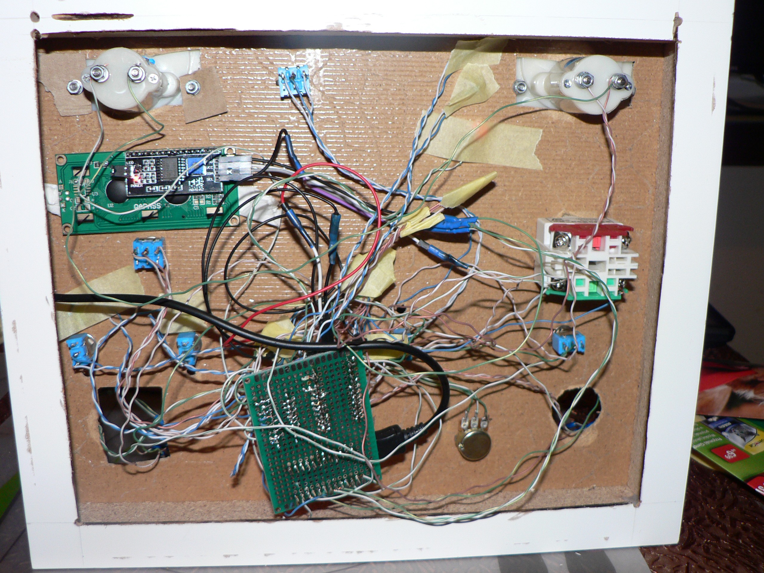
At that time I had a rat's nest of wires and finding the cause took me about two more hours. Surprisingly this was the only problem. I didn't have any issues with shorts or disconnected wires.
![]()
The last mistake was to keep the wires to each component as a twisted pair. After soldering all the signal wires it became too difficult to untwist the ground and power wires. Next time I would try to solder only the signal wire, keep the wires separate and make a kind of bus out of ground and power rails after everything is mounted into position.
Or maybe I will buy proper connectors.
The back:
![]()
The yellow paper protects signal cables for six indicator LEDs that I will add later.
This is the front. Joysticks and OLED display still not mounted and LCD is mounted press-fit using some soft paper compressed between the module and edge of the hole.
![]()
-
LACK of enclosure
12/31/2015 at 10:54 • 0 commentsOn December 28th I did drilling and cuting into LACK shelf to make an enclosure for the panel.
First I cut into bottom of the shelf making a rectangle with about 2cm margin on each side excapt the back side with hinges. There is a thicker board there and you need at least 3cm margin. I left these margin parts on the back to make sure that the whole box will remain more or less rigid.
I tried to use Dremel rotary tool with a fiberglass cutting wheel to make a precise cut, but it wasn't a good idea. With slow rotation it can't cut the board and with high speed it burns it. It is much easier and faster to use an oscillating tool with proper wood saw blade.
Inside of the shelf there is some cardboard in a honeycomb pattern. It's easy to remove it by hand.
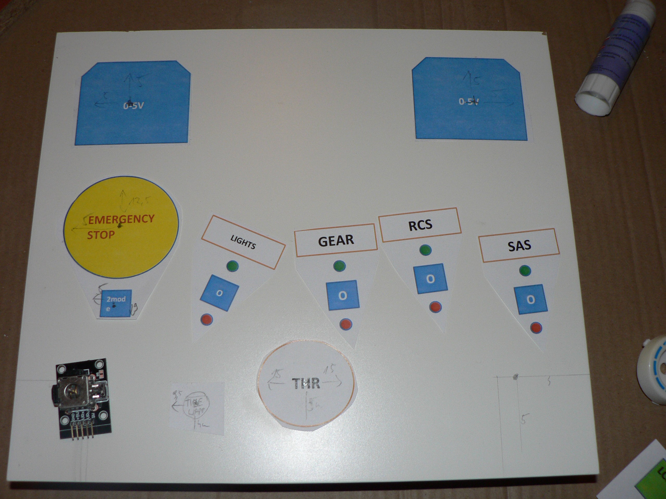
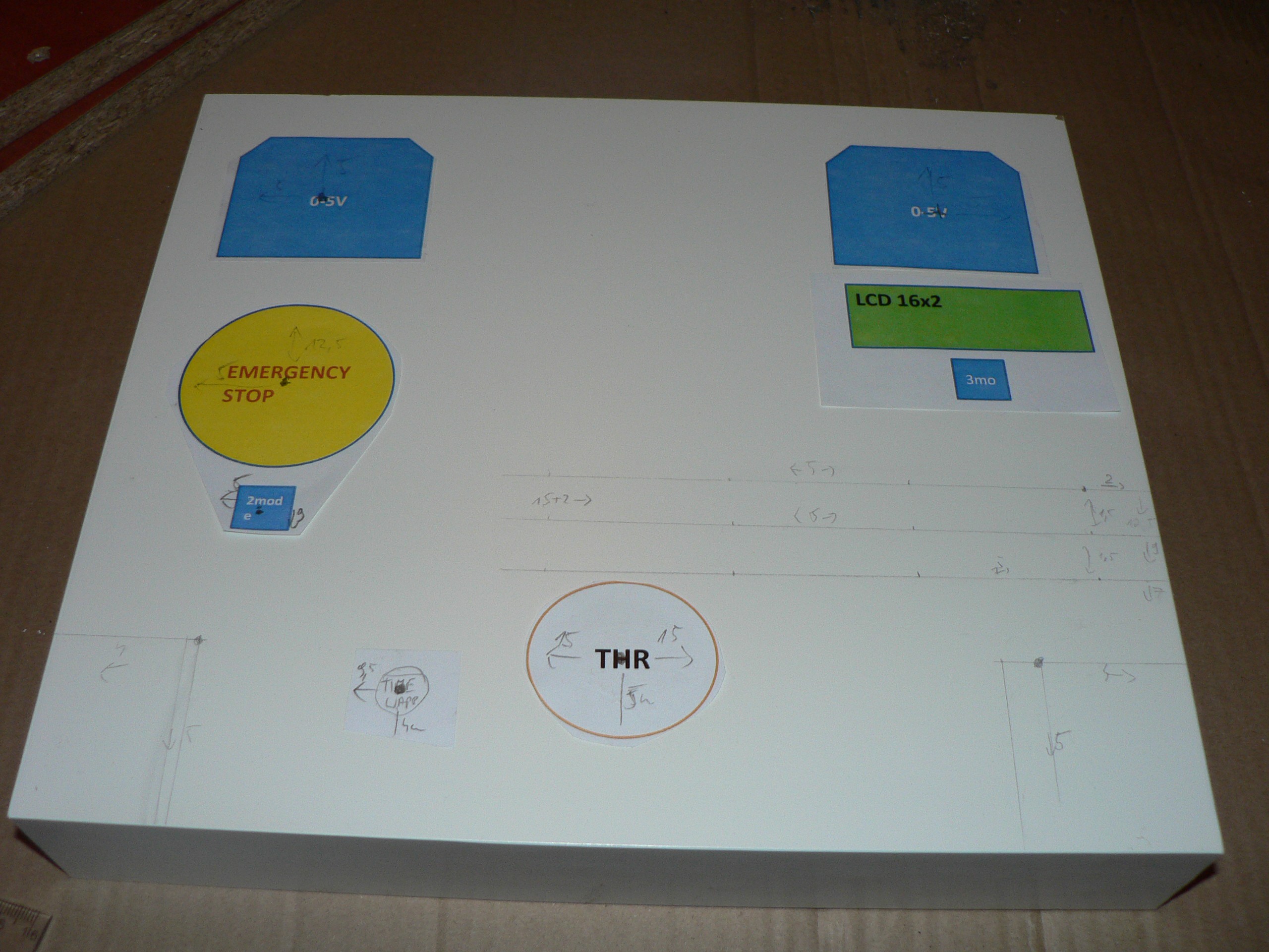
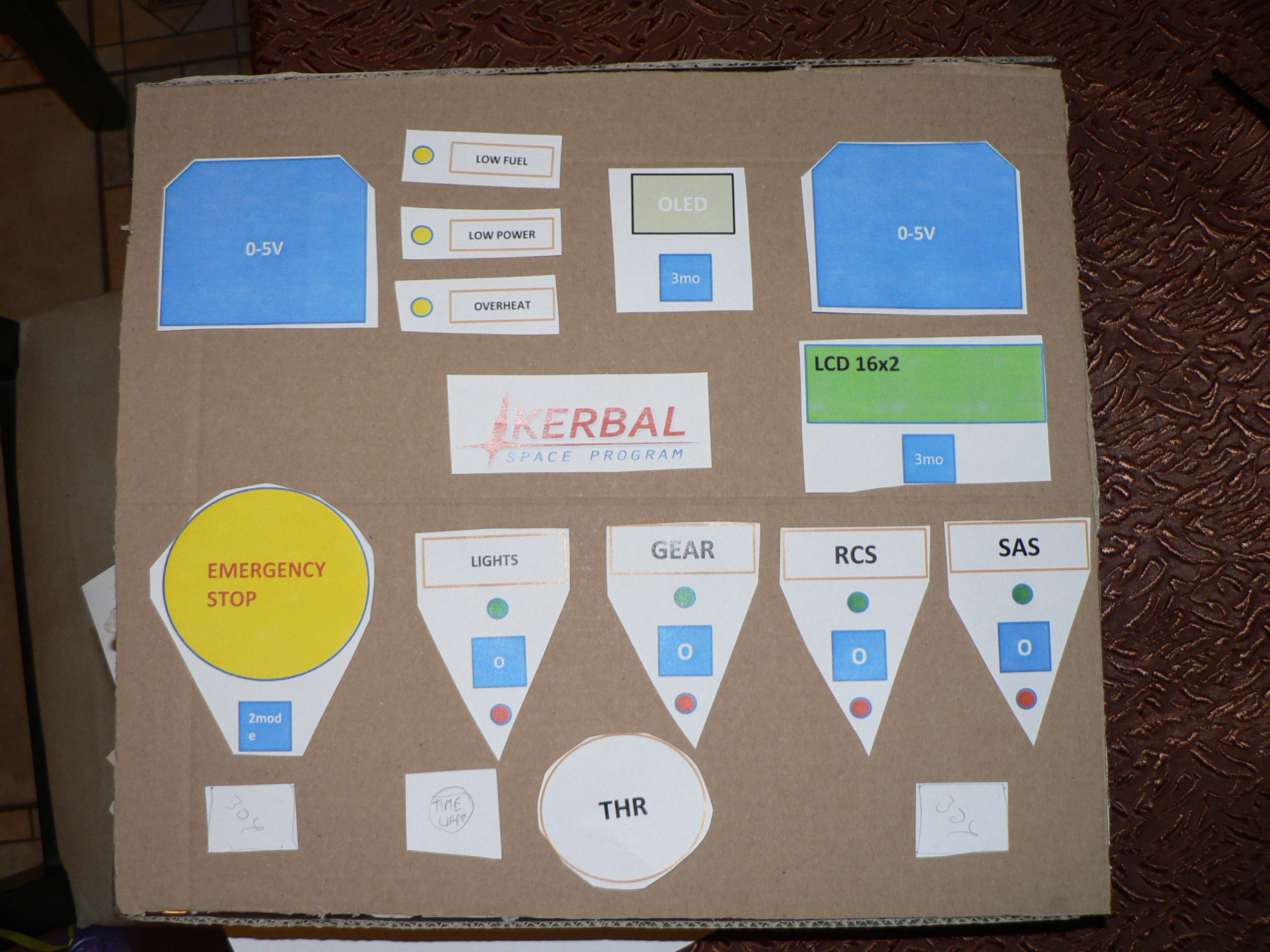
I had a general idea how the panel is supposed to look like, but I was to lazy to prepare a proper design with dimensions before starting this work. I decided about dimensions and made the holes at the same time.
Here is the early stage prepared with paper templates.
![]()
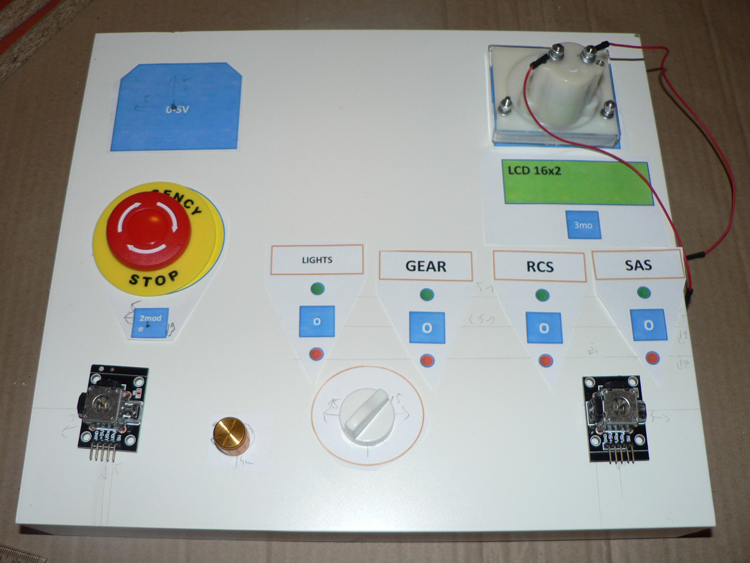
Now wIth more careful layout and actual knobs.
![]()
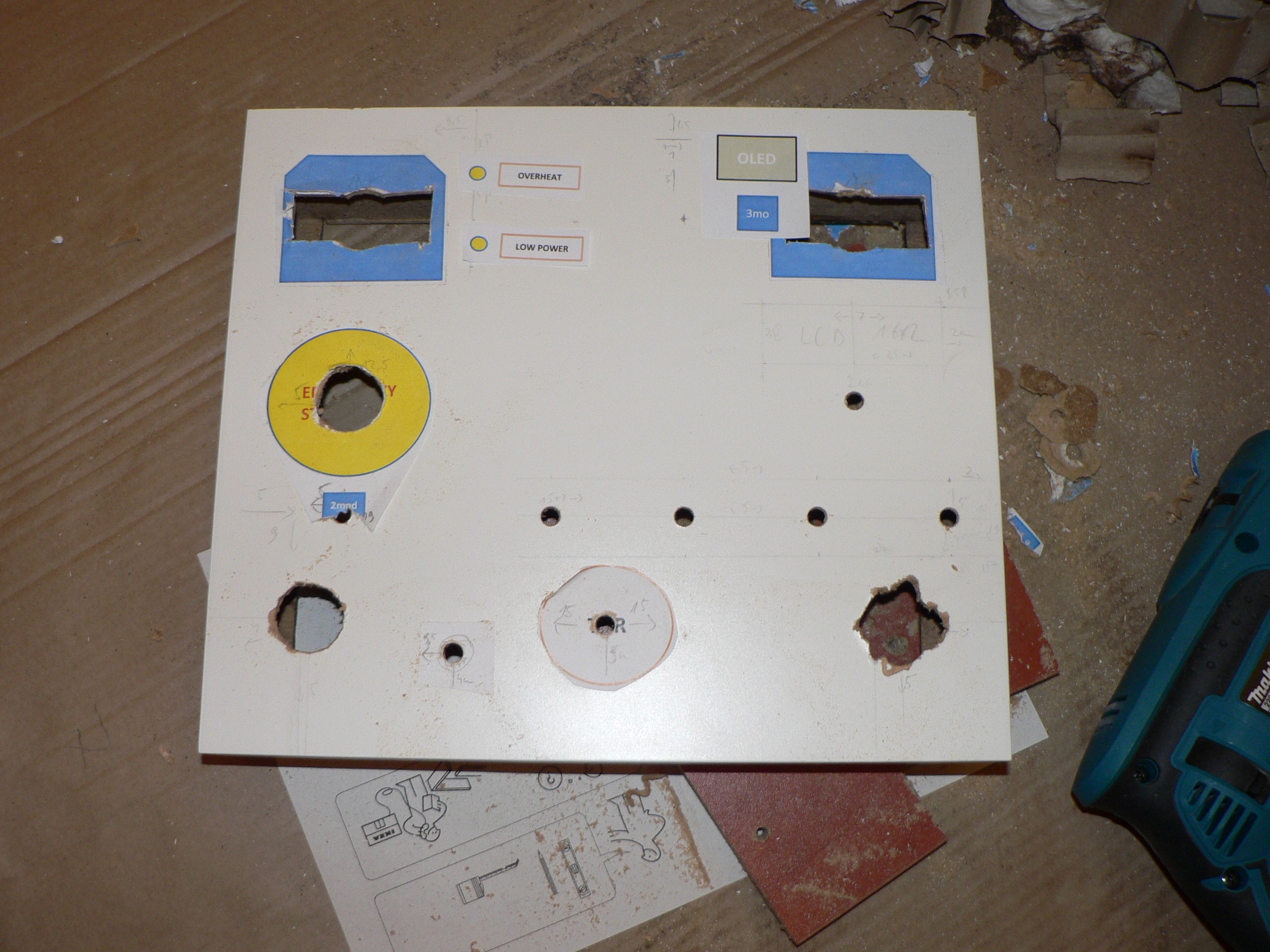
I used ruler and pencil to mark the dimensions of each component's place.
![]()
Then I started drilling and cutting. It was easy, just remember to make the holes on slow speed. I was too happy on the drill trigger. That's why joystick hole on the right looks like this:
![]()
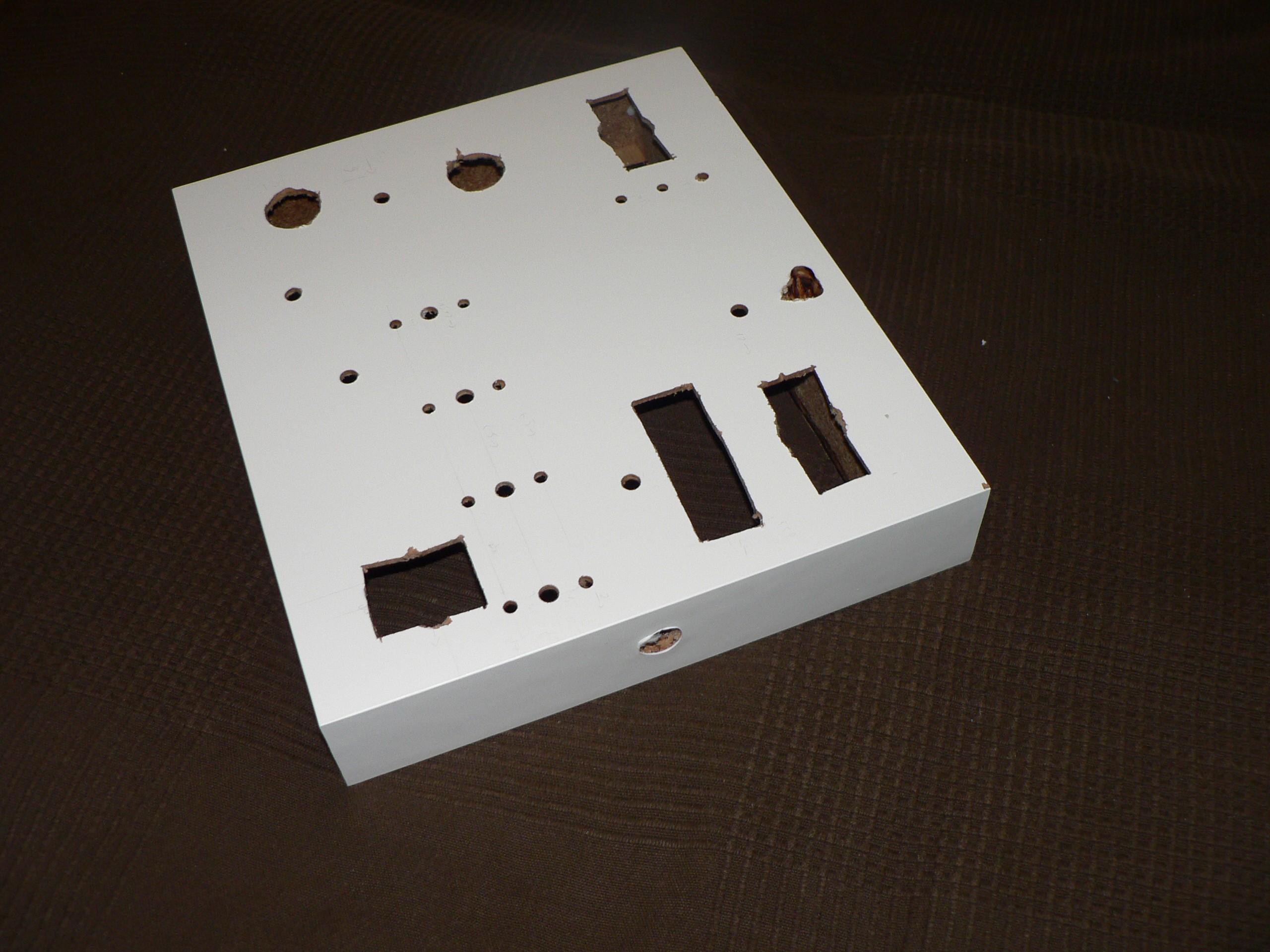
No big deal. I still didn't have clear idea how to mount joysticks.
Here is the final result. The big holes were done with 25mm diameter drill, the switch and potentiometer holes had 7mm drill bit and LEDs have 5mm holes. The hole on the side for cable has 16mm.
![]()
I made the ugly joystick hole recangular to try different ways of mounting them. The uneven thing on the top was supposed to be the hole for OLED screen, but I forgot about 3cm clearance so I hit the back board that made the drilling much more difficult. It will be covered somehow.
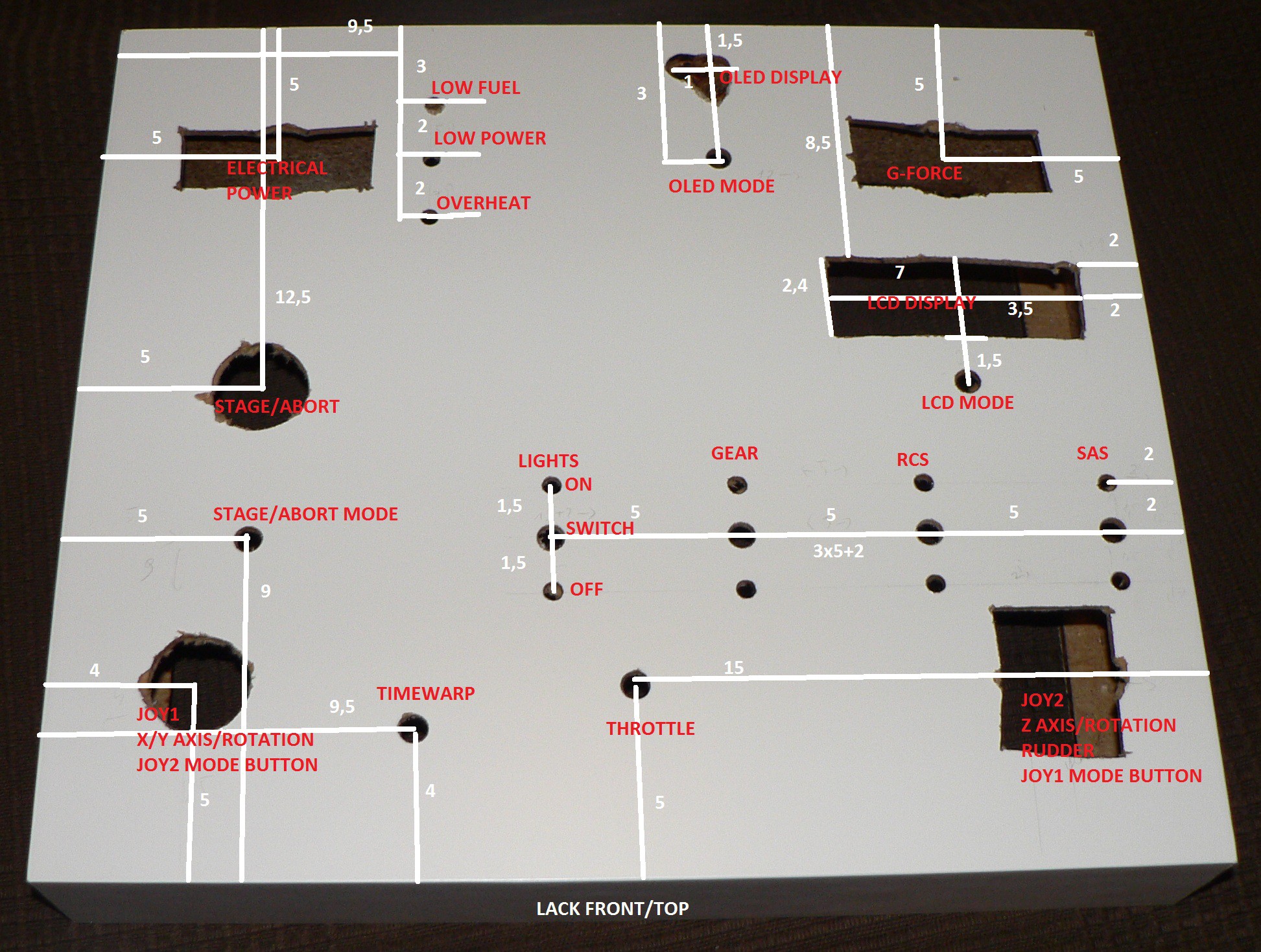
Finally, here is the picture with all the actual dimensions, all numbers are in centimeters. This as if looking on the LACK shelf from front and on top. If you try to hang it, the wall would be in the back of this picture.
![]()
Note: the 9,5 distance should point to the middle of LOW FUEL/LOW POWER/OVERHEAT LED holes.
-
Code is complete
12/24/2015 at 00:52 • 0 commentsThe software part is ready. It may need some tweaking and I still don't know what LCD should display in 3rd mode or what should go to OLED screen (even if there should be OLED screen), but the control and display parts on the Arduino Micro/Mini side are ready.
What works:
- digital input (switches) - either to change mode of operation (LCD display mode, joystick axis/rotation switch) or operate as a button
- analog input (potentiometers) - two X/Y joysticks and a potentiometer mapped to X/Y/Z/throttle/rudder joystick axes and one additional potentiometer for timewarp control
- analog output (voltage display) - works nicely, but there is power issue (see below) to be solved
- translation of switch+potentiometer actions to a emulated joystick with 8 buttons and 6 axes (X/Y/Z axis+rotation), throttle and rudder
- LED display - off, on, blink
- LCD display - connected through i2c to save time and space
- OLED display - will work, I have no use for it right now but there should be enough flash left for u8glib library and some display code; in the worst case it will have very low refresh rate and most of the processing will be done on the PC host side
There is a problem with providing enough power to the circuit. I don't know which part is at fault right now. Either Arduino Micro Pro doesn't negotiate enough current, or its voltage regulator limits available power. With only two uC running the analog voltage display shows me 4,1V on the scale. Earlier tests showed me that with blinking LEDs both analog display and potentiometer readings will swing.
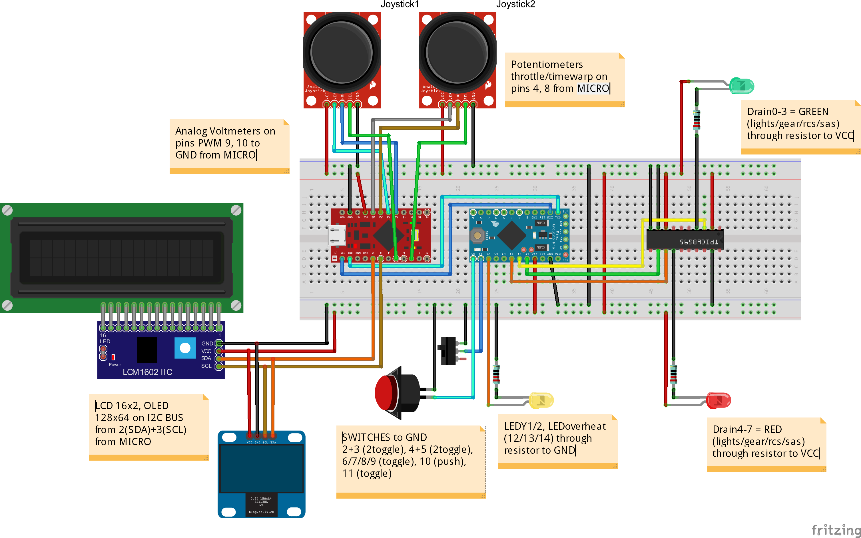
This is the schematic with main components done with Fritzing:
![]()
-
Joystick emulation
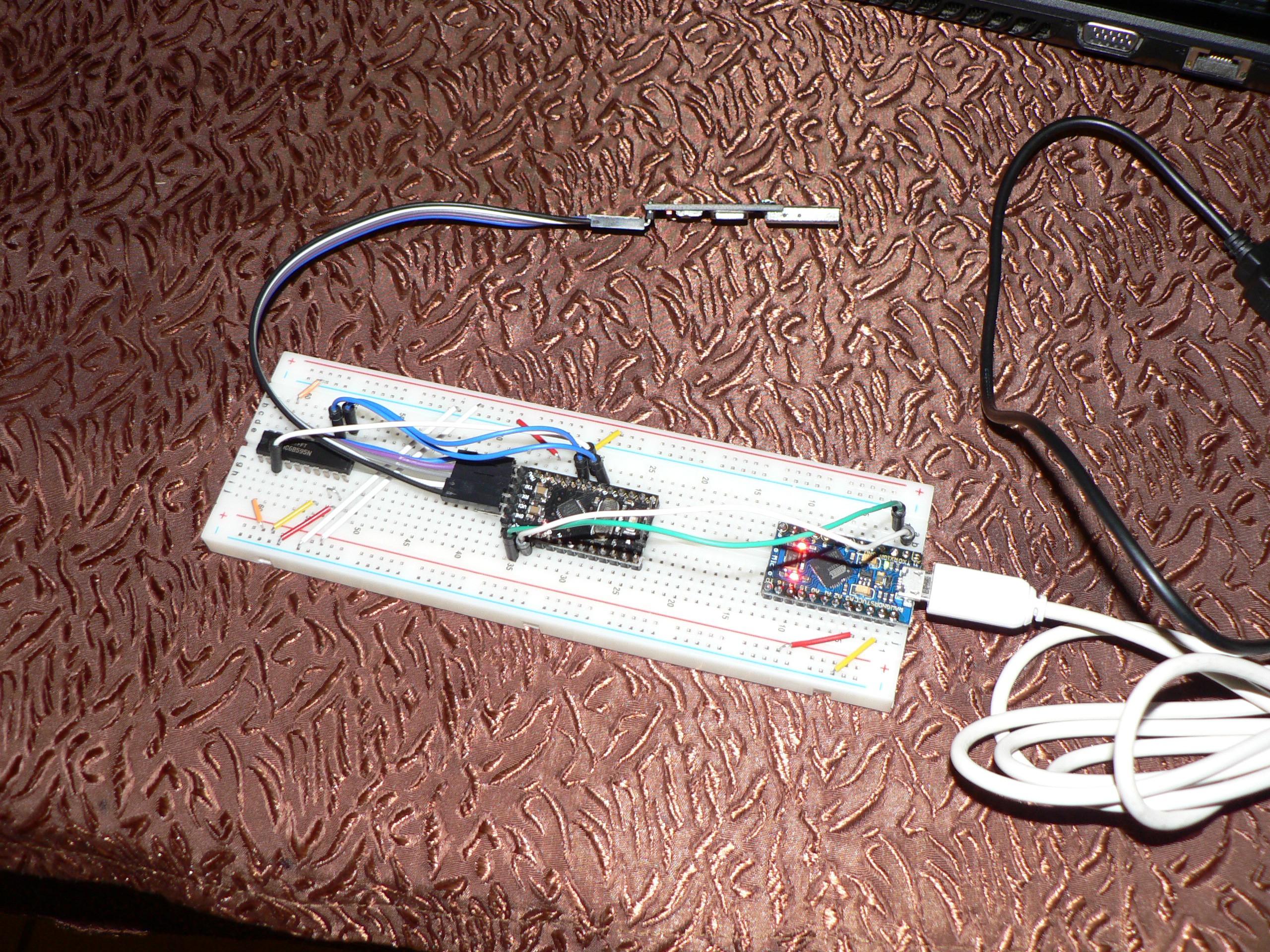
12/21/2015 at 23:55 • 0 commentsHere is the main circuit on a breadboard
![]()
The shift register on the left, driven by Arduino Mini Pro. This part has been tested and proven yesterday. The USB-UART converter is still attached to Mini Pro in case I would have to reflash it.
Mini Pro UART is connected to Micro Pro. Yesterday the only function of Micro was to pass the messages through USB (so no different than USB-UART) back and forth between PC host and Mini.
Today I have added the first part of joystick emulation using Arduino Joystick Library. Some of the button press/release messages from Mini are intercepted and converted into joystick button events.
-
The first log entry
12/21/2015 at 22:33 • 0 commentsThis is where I start to write descriptions about this project.
It has been going on and off since autumn 2015. I noticed that my 3-years old son likes to watch how rockes go and explode and I thought it would be fun to have some physical control board for the game. Something more "real" than a USB gamepad or flight controller that you can buy.
The project somewhat grew since this time because I bought more nad more items through Aliexpress and I found them useful to be included.
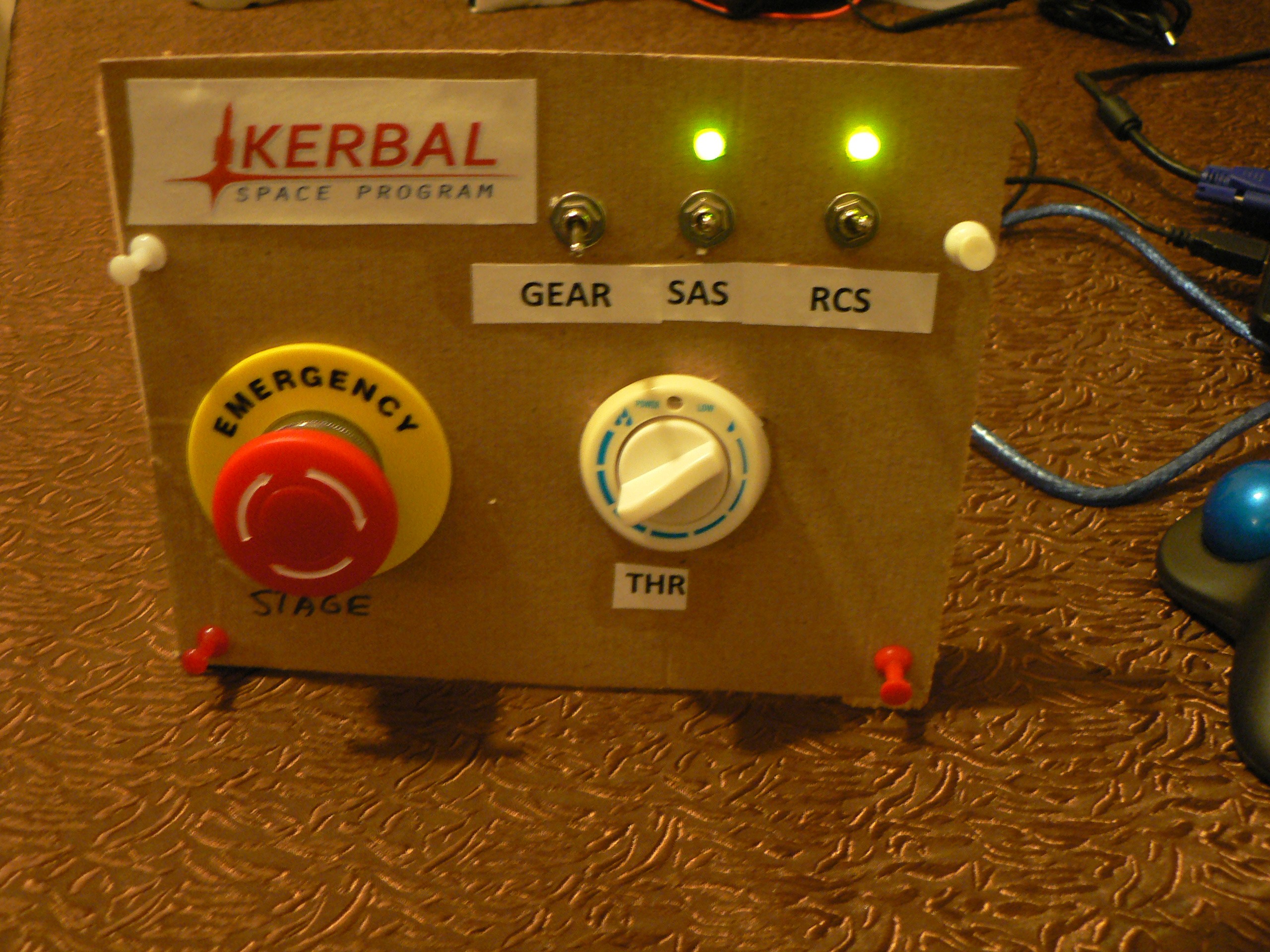
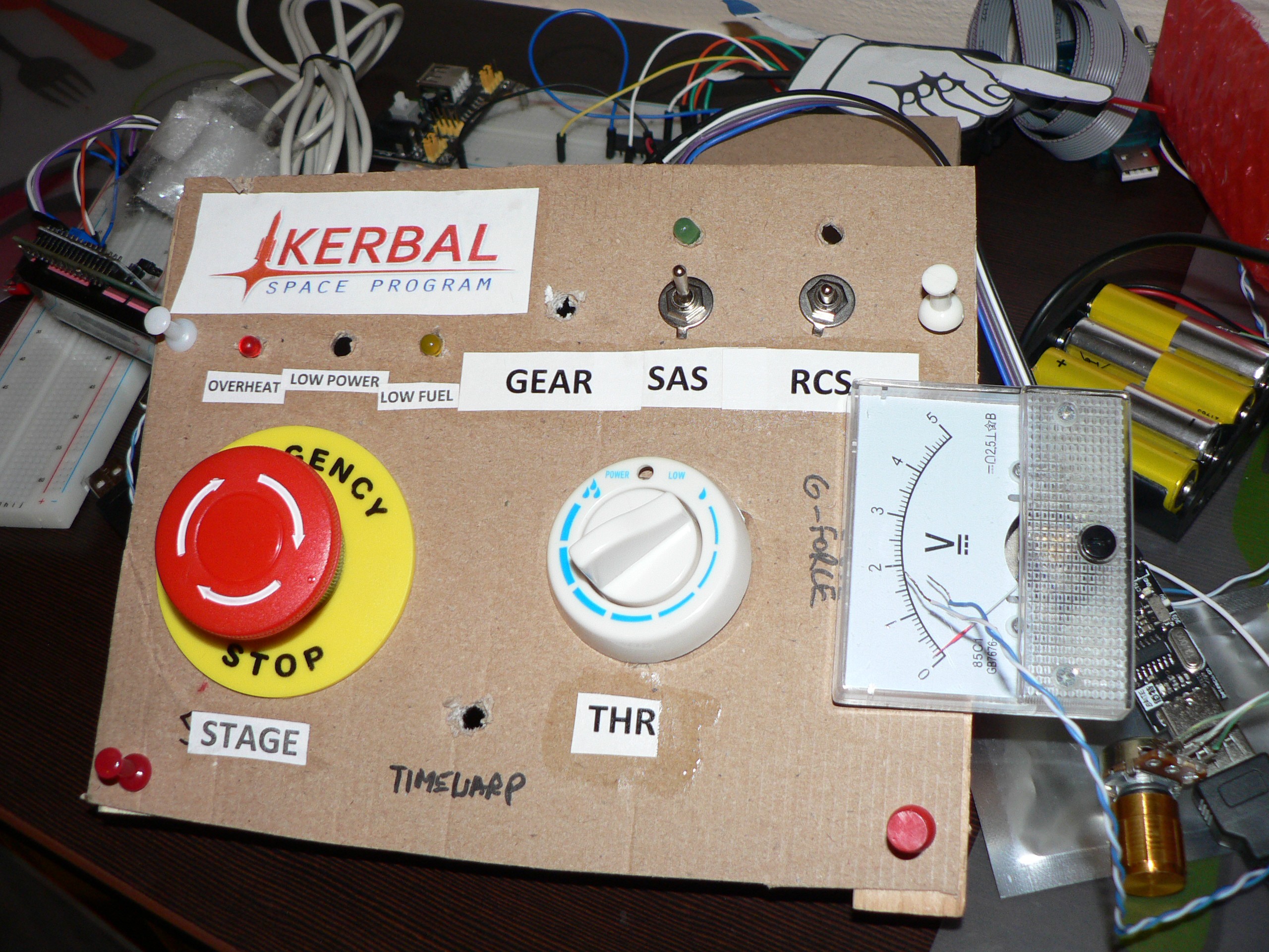
Right now the first prototype on a cardboard was proven.
![]()
It was done with Arduino Mini Pro only with USB-serial interface. It was too fragile to give a 3-yo to play with, but it proved for me that it makes sense to continue this project and gave me new ideas how to improve ergonomy.
![]()
As of today I continue work on the second prototype.
I'm going to write the code first and drill the holes in wood later.
![]()