Yann Guidon / YGDES
-
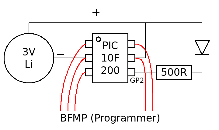
Circuit
03/31/2018 at 04:11 • 0 commentsYou can't make it simpler...
![]()
The PIC is directly powered from a primary Lithium battery.
The LED is connected to a free pin of the PIC through a resistor (the value depends on the colour and the brightness). The more resistance, the less current, the longer the coin cell lasts...
I have chosen to use a low-side switching on GP2 but this is software-configurable.
5 wires are soldered on the pins for programming purposes. Once the chip is programmed and tested, the wires can be cut.
That's all.
-
Encoding
03/26/2018 at 10:58 • 0 commentsThe PIC10F has a very, very small addressing space. The PIC10F200 has only 256 instructions in Flash memory and virtually no SRAM space. The message must be stored in the program space as a RETLW array.
The program space must also store the decoding code so the simpler, the better. For example, it's not possible to store a ASCII->Morse translation table. So the message must be stored in a pre-encoded format that is both compact and straight-forward to interpret.
I have chosen to limit the Morse "characters" to 5 tics, and the number 5 fits in 3 bits. Hence 5+3=8 and a character fits in a byte.
- 3 LSB give the "tic count" (how many dit/dahs) (the case of 0 means "space")
- 5 bits give the lengths of the respective tics (0 for dit, 1 for dah)
The translation is performed during assembly with a list of #define so the software is very simple and no storage is lost. The whole program is less than 60 instructions...
Morse blinking jewelry
A proof that the PIC10F200 can be useful after all.