 Alexander
-
KICAD Raytracing
03/14/2019 at 18:48 • 0 commentsKICAD has been growing on me lately. Now that I use Linux full-time, starting a VM or rebooting into Windows just to use Diptrace was getting annoying. It doesn't run well under WINE (despite what the official website seems to imply), and so I've been spending more and more time in KICAD.
The latest version from the Ubuntu PPA is 5.0.2, though 5.1.0 has been released and is making its way down the pipeline. One of the features in the huge overhaul for version 5 was raytracing. Raytracing has been all over the gamer news because of the technology being hardware accelerated by the latest nVidia graphics cards (the RTX2000 series). So when I saw the option for the 3D render to be rendered with raytracing, I tried it out. Of course, without hardware acceleration, the render takes an order of magnitude or more compared to OpenGL, but the results are pretty awesome!
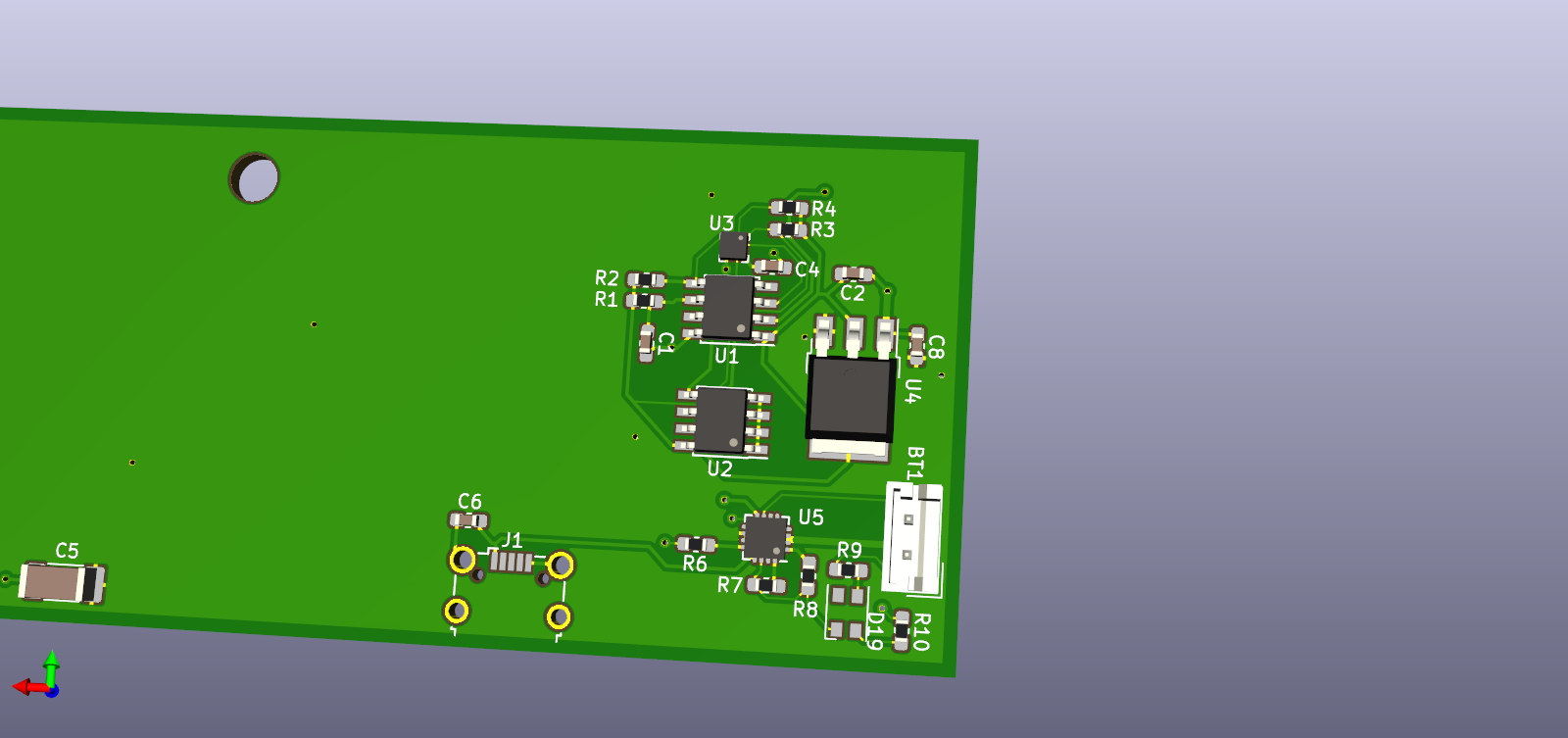
Take a look at a recent board, the same shot rendered in both OpenGL and with Raytracing:
![]()
Rendered with OpenGL ![]()
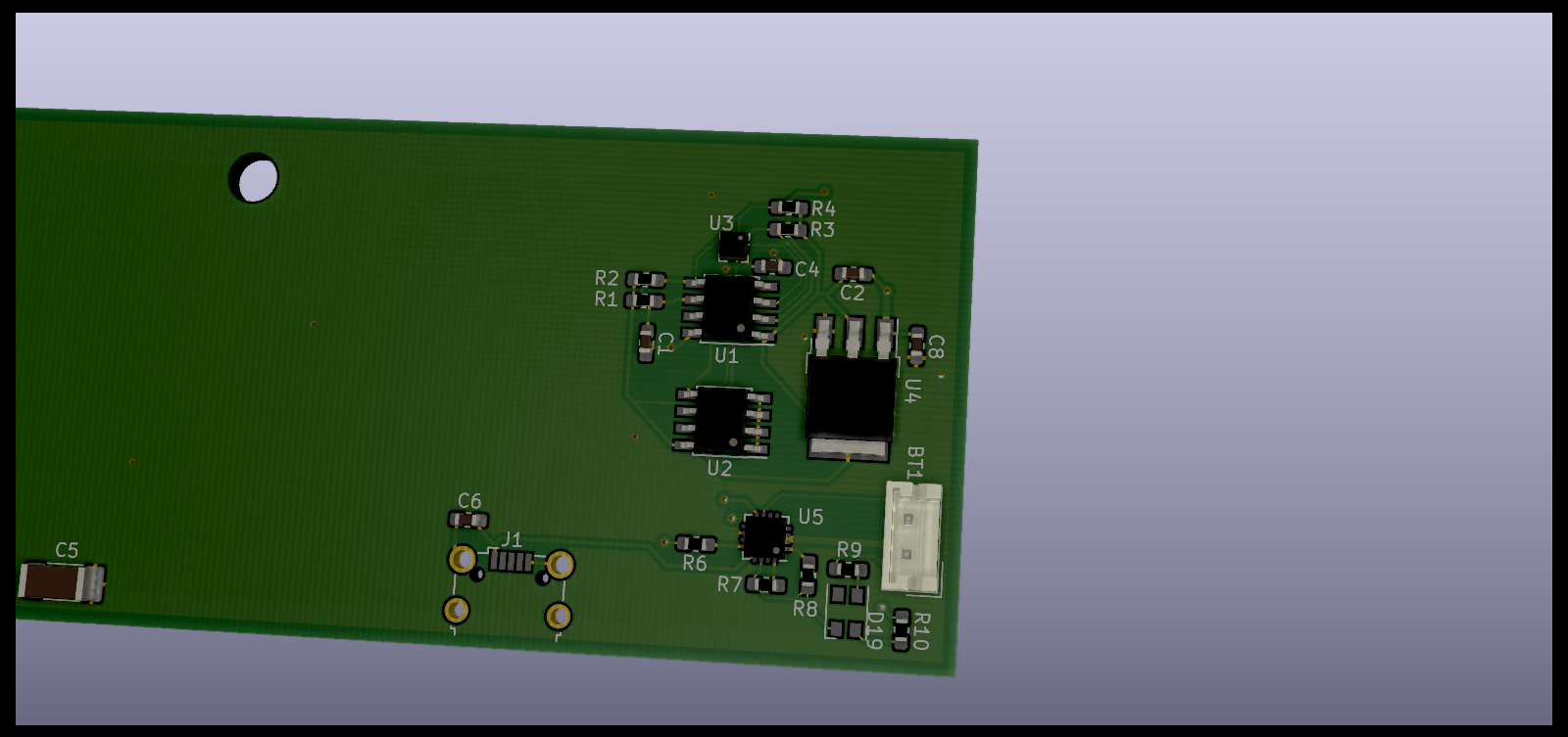
Rendered with Raytracing The board almost looks real! There are still a few kinks to work out (I should maybe try enabling antialiasing) but boy, what an awesome little feature in a free, open-source piece of software!
Give it a try and see what you think!
-
Sigmoid function
07/03/2018 at 05:04 • 0 commentsI recently rediscovered the sigmoid function. It is incredibly useful in many areas of programming, but most recently has seen intense use in the neural network and machine learning software development communities. It takes any number as input, and scales it to between 0 and 1. This allows you to easily get a "true" or "false" out of a floating point number.
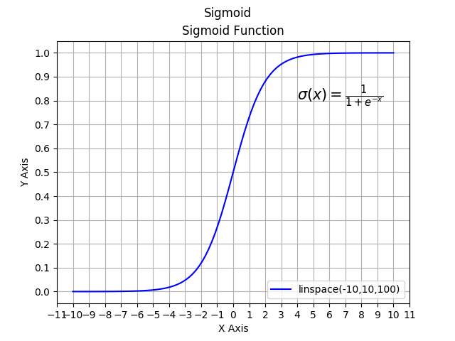
The equation itself is very simple:
For those of you not as familiar with mathematics, here is the article on e. It's equivalent to about 2.71828 (50 digits in the above figure). For most use cases a shorter approximation is fine, but sometimes you may need many more significant digits. The function has a very characteristic S-shaped curve (hence the name sigmoid), which looks like this:
![]()
Implementing this equation is quite easy in many languages. Let's take a look at an implementation in C:
#include <math.h>

double sigmoid(double x) {
     double result;
     result = 1 / (1 + exp(-x));
     return result;
}
This is very easy as the C standard math library includes the exp() function, which returns e raised to the number given. We could create our own exp() function if we didn't want to use the math library, although we would also have to create our own pow() function as well.
Why don't we take a look at sigmoid in Python? It's just as simple as the C example.
import numpy as np
def sigmoid(x):
    return (1 / (1 + np.exp(-x)))
Like the C example, this Python depends on the function exp from the numpy library. You can install numpy using pip. Pretty awesome, right? Try using the function in some code! There are other variations on sigmoid in case you want the 'linear' region to be steeper or shallower, as well as many other tweaks. These are all listed in the Wikipedia article I linked earlier.
Let me know if you've ever used sigmoid in the comments!
-
KiCAD trial
07/03/2018 at 04:16 • 1 commentI really love DipTrace. I’ve used it for a few years now, and I am so familiar with its inner workings that I can be very efficient while using it. The prices for the full version are reasonable, but I use the free non-profit version. While this doesn’t limit layers, it does limit the number of pins to 500. It’s fairly rare that I come even anywhere close to that, but with some projects I start to get worried that I’ll run out.
DipTrace, while professionally made and with a decent user base, is not one of the top CAD programs used in the EE industry. The most common ones you’ll find are Altium Designer (super $$$), Eagle (reasonably cheap), Mentor Graphics PADS, Cadence Allegro/OrCAD (also $$$), and now, to a degree, KiCAD. While there have been a few attempts at open-source EDA software over the years, KiCAD is the first to have some widespread adoption. Helped by a team at CERN who not only started using it, but also assigned staff members to actively develop it, it has grown out of being a difficult to use, obtuse and frustrating tool into something that more and more designers are switching to. The fact that it is OSS means there are no restrictions on board size, number of layers (they go to 16), or pin count. The downside to every OSS project, of course, is that with so many developers all over the world working on a project, it can move more slowly and take longer to become a polished product. This was the #1 concern of many designers. Dave Jones of the EEVBlog mentioned on the Amp Hour many times that he had played with it and didn’t like it. He struggled with the installation process, the fast updates and constant version changes, and, naturally, the unfamiliarity.
![]()
Main window of Kicad Many of these problems have been fixed over the last year or so. They now use a stable version, which is good for everyday use, while maintaining a nightly version which updates more frequently. They’ve also polished some of the rough edges, and made the UI a bit easier to use. The main window now has a more logical flow, and shows you all the tools available with a description of each. All your saved project appear on the left-hand side, using a traditional folder hierarchy format. This makes it easy to see all the things you’re working on. I find it interesting that KiCAD have chosen to go with very odd file extensions. For example, their PCB layout files had a .kicad_pcb file extension. This would prevent backwards compatibility with very old operating systems, though that’s not much of a concern these days. I guess it’s important to make sure you avoid extension collisions with other applications.
![]()
The Eeschema capture tool in KiCad I was also pleasantly surprised with the schematic capture. It’s fairly easy to figure out without reading any introduction or tutorials, though it still retains some of the obtuse heritage of its early versions. The biggest example of this, which seems a very odd quirk to me, is that it does not number the component designators as you add components. So when you add an IC, it is labelled as U?. Resistors, R?. Same for all components. You actually have to run a separate tool once you’re finished doing schematic capture to enumerate all the designators. I cannot figure out why you would want to separate that process out. Most EDA software does allow you to do a renumbering if you don’t like the way things have been numbered, but they always have numbers by default. This makes it easier to manage netlists, especially if you have multiples of the same chip. I haven’t gotten into any advanced schematics yet, so I’m not sure how this will turn out in the long run, but besides that quirk the toolbars and UI is laid out quite nicely. Everything has a fairly logical flow.
One of the constant annoyances that I put up with for quite a while before somebody suggested how to fix it is the way KiCAD zooms and pans. In DipTrace, when you scroll the mouse wheel, it uses the position...
Read more »
My Projects
My Pages


Things I've Built
PIC32 Dev Board
Back when I first started working with the PIC32MX series of chips, I whipped up a dev board which ended up going through a few iterations. Here is the final design I went with!
Projects I Like & Follow
 bobricius
 Capt. Flatus O'Flaherty ☠
 ptrav
ptrav Luca
Luca foamyguy
 Ali
Ali Hpsaturn
 Futience
 Maya Posch
 t3chflicks
 Mike Rigsby
 Aleksandar Bradic
 Stefan
 typematrix
Share this profile
ShareBits


Patrick Van Oosterwijck
wrote 09/11/2019 at 20:50
•
point
Hi, thank you for your interest in my wESP32 project!
Thanks for the like and follow on my #Fruit Cake :)