-
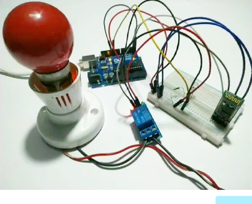
HOME AUTOMATION ARDUINO AND BLUETOOTH
12/04/2020 at 13:15 • 0 comments![]()
INTRODUCTION:-
We all have various automatic houses and places and are very fascinating and attractive so today I am going to tell you how you can make your own home automation with the use of Arduino and Bluetooth module. It is very easy to make and program for person who are in Arduino and robotics. Along this we will be using some other basic stuff to make it working.
We may make our custom app or used which are available on the google play store for free. These apps sends and receives data over Bluetooth connection. Rate of sending data is relatively high and it also depends upon the type of module used like HC-05,HC-06. 5v relays will be used to control 220v/110v AC devices.
DESCRIPTION:-
Arduino are most common microcontroller which can be used in various ways and also can be hooked to any module and sensor very easily. It is used widely among hobbyist to make different and interesting projects. Today we are using the most common Arduino available (uno) and HC-05 Bluetooth module to make some interning prioject5.
Bluetooth apps are available for free on google paly store or any other app store or you can make your own custom app in MIT app inventor or any other platform
*NOTE:- SPEED OF DATA TRANSFERRED DEPENDS UPON THE MODLE OF MODULE YOU ARE USING AND OPEN AREA OR OBSTACLES IN BETWEEN THE RECEIVER AND TRANSMITTER DEVICES.
FEATURES AND APPLICATIONS: -
- Accessible from any Bluetooth device.
- Easy to use
- Signals can be weak due to obstacles
- Low price
- High speed data transfer
- Can be used in small projects and home automation.
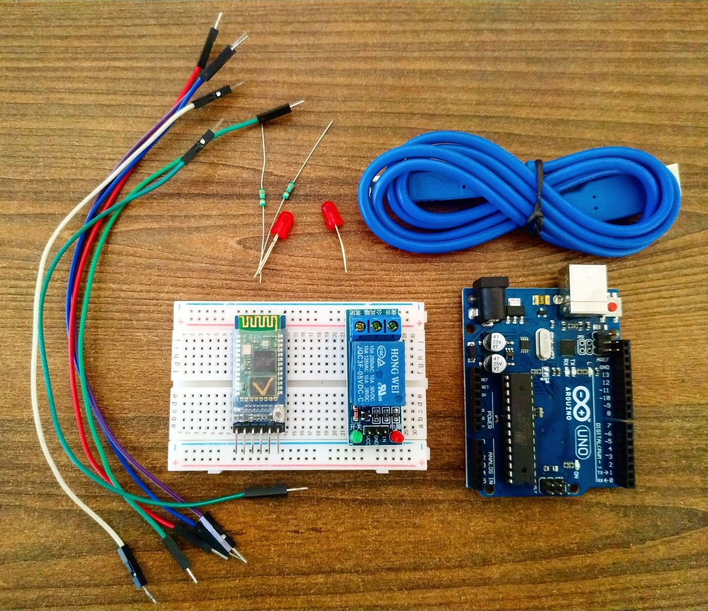
COMPONENTS NEEDED: -
![]()
- Arduino Uno and its cable
- Relay module
- Bluetooth module
- Bread board
- A LED
- Resistor(220ohm)
- Jumper wire
- AC Bulb and holder
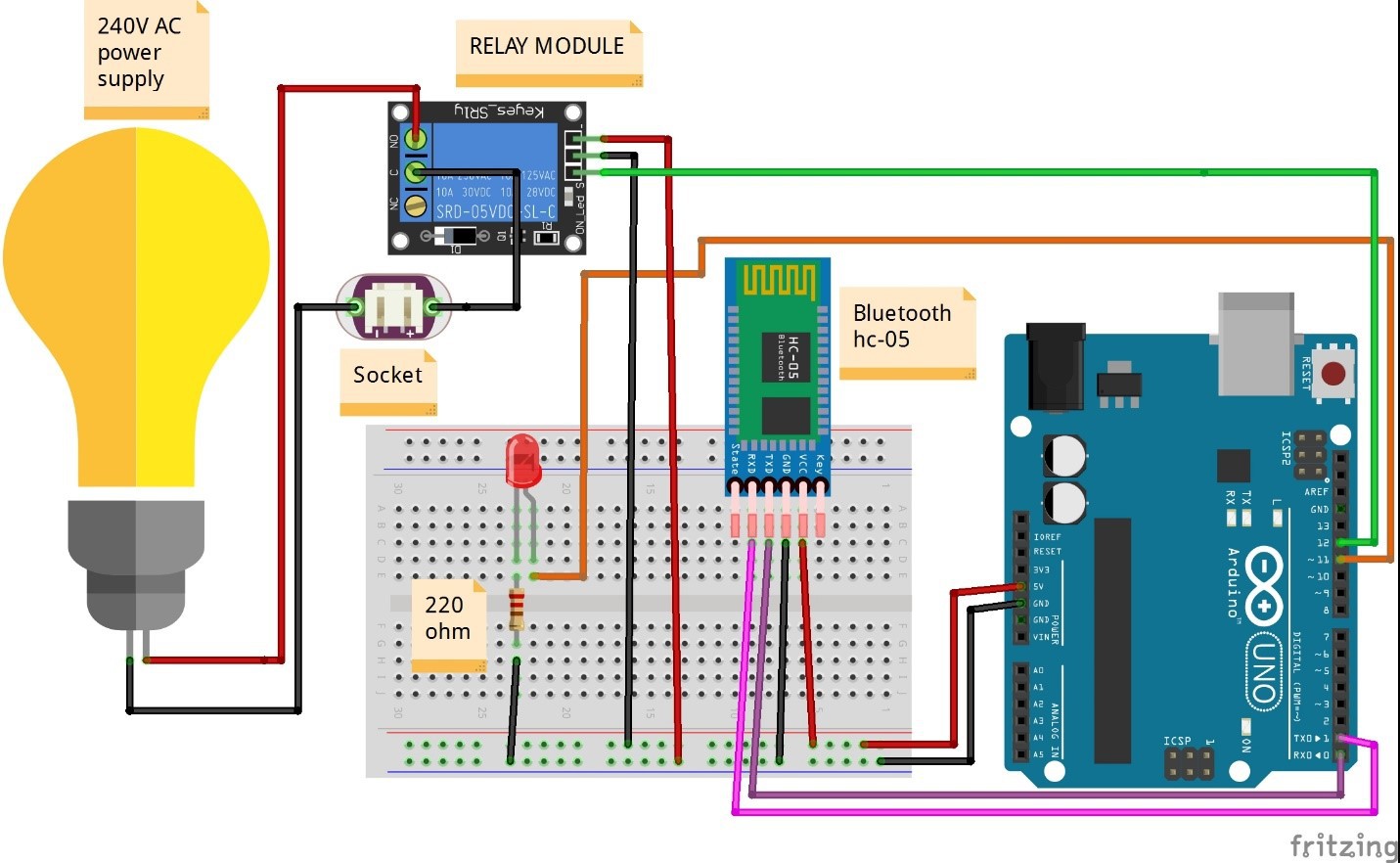
CIRCUIT DIAGRAM:
![]()
First take the power lines onto the bread board from microcontroller
VCC/5v-->+ line and GND--> - line.
Then connect Bluetooth module on to the bread board and connect power to the module from powerlines using jumper wires.
Now connect Rx AND Tx PINS OF BLUETOOTH MODULE TO ARDUINO Tx and Rx PINS RESPECTIVELY OR AS SHOWN IN FIGURE ABOVE.
Now connect leds to the breadboard +to PIN 11 and - wire to GND in series with a resistor.
Now connect relay module to power lines on bread board and AC power lines in series with an AC bulb as shown. Also connect signal pin of relay module to PIN 12 of ARDUINO
CODE AND APP: -
LINK FOR APP IS ………………………..
//put this code in the ide of Arduino from this line
void setup()
{
Serial.begin(9600); // buart rate
pinMode(12,OUTPUT); // RELAY MODULE
pinMode(11,OUTPUT); // LED
digitalWrite(12,HIGH); // relay module high
}
void loop()
{
if(Serial.available()>0)
{
char data= Serial.read();
Serial.println(data);
if(data=='a')
{
digitalWrite(12,LOW); // RELAY ON
digitalWrite(13,HIGH); // LED ON
Serial.println("RELAY AND LED ON");
}
if(data=='b')
{
digitalWrite(12,HIGH); // RELAY OFF
digitalWrite(13,LOW); // LED OFF
Serial.println("RELAY AND LED OFF");
}
}
}
WORKING:-
As the code starts it initializes the pin to which relay module is connected and to which led is connected. After initializing it waits for the serial data to be received as soon as the data is received it check th condition for the received string.
Then according to the condition, it switches on or off AC bulb and simultaneously a led for indicating that data is successfully received.
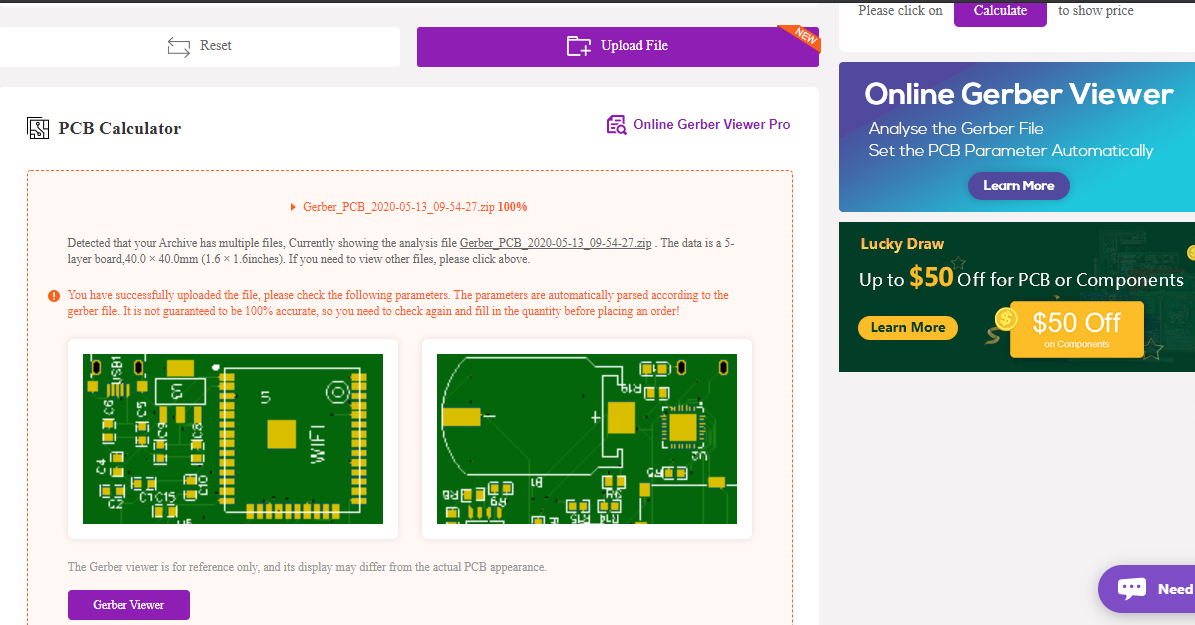
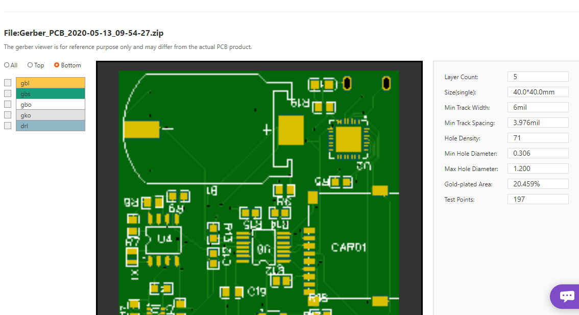
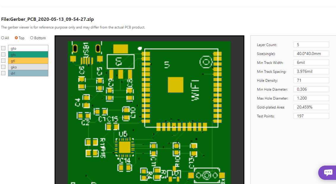
PCB DESIGNING:-
![]()
![]()
![]()
Now as we have developed our circuit and ordering it. For ordering PCB, I would prefer you NextPCB which is a great website for ordering custom PCB with high quality and...
Read more -
HOME AUTOMATION USING BLYNK APP AND ESP8266
12/04/2020 at 13:13 • 0 comments![]()
INTRODUCTION:-
We all have various automatic houses and places and are very fascinating and attractive so today I am going to tell you how you can make your own home automation with the use of ESP8266 and Blynk app. It is very easy to make and program for person who are in Arduino and robotics. Along this we will be using some other basic stuff to make it working.
Blynk app sends and receives data over a secured and encrypted protocol for which it needs access to internet and same for the ESP8266, it also needs constant wifi connection so as to control devices attached to it. 5v relays will be used to control 220v/110v AC devices.
DESCRIPTION:-
ESP8266 is another most common IOT platform microcontroller which is used widely among hobbyist to make different and interesting projects. It comes in various models like Wi-Fi, Wi-Fi + Bluetooth and Bluetooth. Today we are using the most commonly one available in the market that is Wi-Fi one.
Blynk app is available for free on google paly store or any other app store. It is free to use and comes with various functions to perform but it comes with limited amount of energy which is required to perform operations. So if you want more actions to be performed than you have to create your own home server for which link is given (https://github.com/blynkkk/blynk-server)
*NOTE:- SPEED OF DATA TRANSFERRED DEPENDS UPON THE SPEED OF YOUR CONNECTION AND CORRECT INITIALS OF THE ENCRYPTED KEY YOUE RECEIVED ON YOUR E-MAIL ID.
FEATURES AND APPLICATIONS:-
- Accessible from any part of world
- Easy to use
- No limit of devices but restricted to pins on microcontroller
- Low price
- Can be used in small projects and home automation.
COMPONENTS NEEDED:-
- NodeMCU ESP8266 and its cable
- Relay module
- Bread board
- Jumper wire
- AC Bulb and holder
CIRCUIT DIAGRAM:
![]()
First take the power lines onto the bread board from microcontroller
VCC/5v-->+ line and GND--> - line.
Then connect the relay module to the power lines on bread and also to 220/110V AC supply as shown in above diagram.
Now connect SIGNAL PIN OF RELAY MODULE TO ESP8266 PIN
Now connect Ac bulb in series with relay module AC supply as shown above.
CODE:-
//put this code in the ide of arduino from this line
//blynk library link
//https://github.com/blynkkk/blynk-library
#define BLYNK_PRINT Serial
#include <ESP8266WiFi.h>
#include <BlynkSimpleEsp8266_SSL.h>
// You should get Auth Token in the Blynk App.
// Go to the Project Settings (nut icon).
char auth[] = "authentication token received on email id";
// Your WiFi credentials.
// Set password to "" for open networks.
char ssid[] = "wifi id";
char pass[] = "password";
void setup()
{
// Debug console
Serial.begin(9600);
Blynk.begin(auth, ssid, pass);
}
void loop()
{
Blynk.run();
}
WORKING:-
As the code starts it initializes the pin to which the relay module is connected and then waits for the data received through Wi-Fi.
After it receives the value it then turn on or off the bulb according to the value received through blynk app.
PCB DESIGNING:-
![]()
![]()
![]()
Now as we have developed our circuit and ordering it. For ordering PCB, I would prefer you NextPCB which is a great website for ordering custom PCB with high quality and precision on time delivery. Ordering PCB online in various sites are a step towards developing our own circuit. NextPCB provides very easy and fast delivery of PCB in different masks and paste with professional look. Also, they send you the picture of your PCB before shipping it to you, Now that very exciting….The Gerber File for the PCB is given below. You can simply download the Gerber File and order the PCB from :Gerber Viewer of NextPCB
Go to get your discount: NextPCB
#arduino #arduinouno #arduinoproject #arduinomega #arduinonano #arduino duo
-
MUSIC REACTIVE LED
12/02/2020 at 16:40 • 0 comments![]()
INTRODUCTION:-
We all have seen vu meters in every music system and various other recording devices but never wondered to create such a thing ,so today I am going to tell you a simple and easy way by which you can create a simple vu meter by your own which will react to music and other small sounds but it all depends on the quality of mic used.
Simple vu meter kits are available on every e commerce sites at a cheap price but if you have an Arduino uno do could do more with it just making a vu meter. So here we are going to make a simple vu meter which you can make use in something more attractive and bigger task like changing color of RGB light.
DESCRIPTION:-
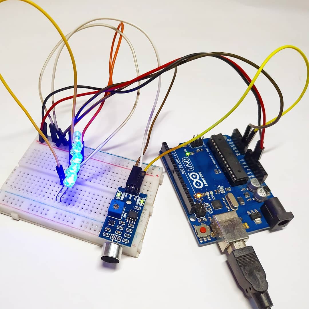
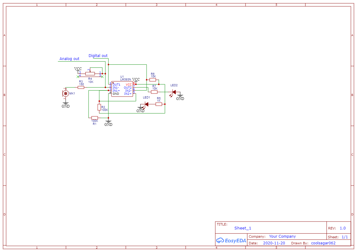
Here we are going to use some of the common components that every robotics hobbyist will have. In this we are going to use sound sensor which is built out of LM358 ic a condenser microphone a variable resistor to trim the values of range of the value given by the sensor to the microcontroller.
Sensor also has an onboard power led and also an onboard Status led which will blink whenever the sensor detects some sound
The sensor gives analog output which varies according to the sound input in the microphone also on the variable resistor as LM393 amplifies the sound acc to the variable resistor value.
*NOTE:- THIS SENSOR IS BASED ON CONDENSER MIC WHICH NOT A GOOD QUALITY ONE I RECOMMECD YOU TO USE THIS MIC FOR SOMR COMMON PROJECT BUT IF YOU WANT FOR AN PROFESSIONAL ONE I RECOMMEND YOU A GOOD QUALITY MICROPHONE AND AN BETTER AMPLIFIER IC.
SCHEMATIC DIAGRAM:-
![]()
FEATURES AND APPLICATIONS:-
- Sensitivity of sound is good
- Easy to use
- Adjustable value
- Low price
- Can be used in small projects and vu meter devices
SENSOR SPECIFICATIONS:-
![]()
COMPONENTS NEEDED:-
- Any microcontroller preferably Arduino Uno for beginners.
- A bunch of different led but of same voltage
- A sound sensor
- A breadboard
- Jumper wires
- 220ohm resistor
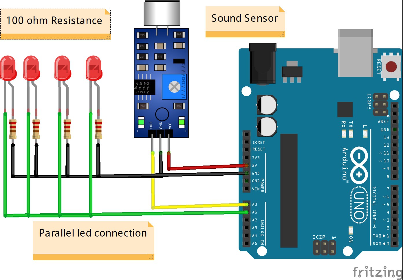
CIRCUIT DIAGRAM:
![]()
First take the power lines onto the bread board from microcontroller
VCC/5v-->+ line and GND--> - line.
Then connect the sensor on to the bread board and connect power to the sensor from powerlines using jumper wires.
Now connect OUT PIN OF SENSOR TO MICROCONTROLLER ANALOG
PIN A0.
Now connect leds to the breadboard – to gnd and + wire to analog pin A1 in series with a resistor to the microcontroller.
CODE:-
//put this code in the ide of arduino from this line
int val;
void setup()
{
Serial.begin(9600);
}
void loop()
{
val=analogRead(A0); // Sound Sensor connect A0 pin
Serial.println(val);
delay(50);
val=map(val, 0, 1023 , 0, 225);
analogWrite(A1, val); // led connect A1 pin
}
WORKING:-
As the code starts it initializes the pin to which the sensor sends its data then the microcontroller waits for the data to be received as soon as the data is received it then maps its value from 0-1023 to 0-255 which is analog output limit.
After it maps the value in val it then sends this value in the form of output range to the anlog pin A1 for the leds to react.
PCB DESIGNING:-
![]()
![]()
![]()
Now as we have developed our circuit and ordering it. For ordering PCB, I would prefer you NextPCB which is a great website for ordering custom PCB with high quality and precision on time delivery. Ordering PCB online in various sites are a step towards developing our own circuit. NextPCB provides very easy and fast delivery of PCB in different masks and paste with professional look. Also, they send you the picture of your PCB before shipping it to you, Now that very exciting….The Gerber File for the PCB is given below. You can simply download the Gerber File and order the PCB from :Gerber Viewer of NextPCB
Go to get your discount: NextPCB
#arduino #arduinouno...
Read more -
AUTOMATIC HAND SANITIZER: -
08/25/2020 at 17:30 • 0 commentsAUTOMATIC HAND SANITIZER: -
![]()
INTRODUCTION: -
In this time of coronavirus (COVID-19) spread hand sanitizing is must and for this people also touches the bottle of hand sanitizers so to prevent it here is another great Arduino based project, which is automatic hand sanitizer dispenser. Pumping of the head of bottle means making contact with its surface, so to ensure safe distance it is a great solution in these time in which contamination is very fast Nowadays the need of hand sanitizer has increased to a great extent that every shop local place has availability to it but no protection so this cab used as a great solution to the uncontaminated and no-contact hand sanitizer mechanism.
DESCRIPTION: -
It consists of various small and easy to available components like ARDUINO UNO, ULTRASONIC SENSOR, RGB LED, RELAY MODULE,12v WATER PUMP, 12v ADAPTER, and few other passive components.
This type of circuit can be fixed in any type of bottle or container so as to make it an automatic hand sanitizer one. The RGB led provide visual indicator of the stratus of the system which we will came to know in further working.
Here we have used ultrasonic sensor because if we use IR sensor than it won’t work properly in brighter or in sunlight areas, so as to define a specific distance and to make the system work flawlessly, we have used ultrasonic sensor.
12v pump is used for this project which is also first cleaned with some type of cleaning agent also wires are covered with heatsink to as to protect it from reaction with sanitizer. The system is powered with a 12v Adapter.
Relay module is used to turn on or off the pump with time and to provide complete 12v power supply to the pump as Arduino work on 5v.
FEATURES AND APPLICATIONS: -
- Easy to make
- Easy to use
- Adjustable distance
- Low price
- Can be in all places
- Visual indicator
COMPONENTS NEEDED: -
![]()
- Any microcontroller preferably Arduino Uno for beginners.
- An RGB led
- An ultrasonic sensor
- A breadboard
- Jumper wires
- 220ohm resistor
- 12v Water pump
- 12v Adapter
- Pipe or tube for pump
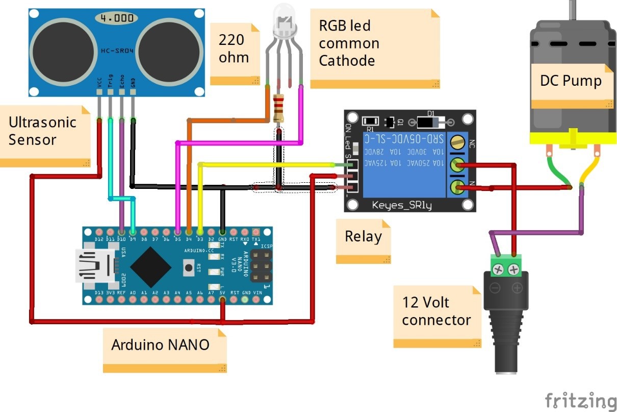
CIRCUIT DIAGRAM: -
![]()
First take the power lines onto the bread board from microcontroller
VCC/5v-->+ line and GND--> - line.
Connect all vcc and gnd of sensor to Arduino 5v taken on Breadboard. Connect 12 v positive supply to relay IN port and from out port to 12v Water pump positive. And make gnd common with Arduino
And then make following connections: -
ARDUINO COMPONENT
D3 ============> RELAY Signal pin
D4 ============> RED LED positive pin
D5 ============> GREEN LED positive pin
D9 ============> TRIG PIN (ultrasonic sensor)
D10 ============> ECHO PIN
CODE: -
int RELAY = 3;
int RED_LED = 4;
int GREEN_LED = 5;
const int trigPin = 9;
const int echoPin = 10;
long duration;
int distanceCm, distanceInch;
void setup()
{
Serial.begin(9600);
pinMode(trigPin, OUTPUT);
pinMode(echoPin, INPUT);
pinMode(RELAY ,OUTPUT);
pinMode(RED_LED ,OUTPUT);
pinMode(GREEN_LED ,OUTPUT);
}
void loop() {
digitalWrite(trigPin, LOW);
delayMicroseconds(2);
digitalWrite(trigPin, HIGH);
delayMicroseconds(10);
digitalWrite(trigPin, LOW);
duration = pulseIn(echoPin, HIGH);
distanceCm= duration*0.034/2;
distanceInch = duration*0.0133/2;
Serial.println("Distance: ");
Serial.println(distanceCm);
if(distanceCm < 10)
{
digitalWrite(RELAY , HIGH);
digitalWrite(RED_LED , LOW);
digitalWrite(GREEN_LED , HIGH);
}
else
{
digitalWrite(RELAY , LOW);
digitalWrite(RED_LED , HIGH);
digitalWrite(GREEN_LED , LOW);
}
}
WORKING: -
As the code starts it initializes the pin to which various components are connected and Green LED starts to glow which indicates that the system is ready to use for. Then ultrasonic sensor checks...
Read more -
HUMIDITY MONITORING SYSTEM
07/12/2020 at 14:42 • 0 comments![]()
Hi Readers, today I am discussing another project that is a Wi-Fi based transmitter using NodeMCU. Some of you must be familiar with NodeMCU that is ESP8266MOD and comes with an onboard Wi-Fi chip for IOT projects. In this one I have used a BME280 Humidity sensor and a NodeMCU to take data from Sensor via I2C and Upload it my server. But continuous use of power can lead to much loss of power and if I use battery if we be dead in several hours of use so I have decided to think for something else and got the solar panel which can be used to charge up the battery every day. In this I have taken an TP4056 battery charging board along with 3.7V to 5V boost converter and an 18650 Li-Ion cell. This cell can easily withstand 2 or three days of continuous power delivery without getting discharged. I used this circuit and was happy form the results. Now I am thinking of designing a specific PCB for the task which will not only reduce the power consumption also provide a smaller space. If you also want your custom PCB to be manufactured, then I will recommend you NextPCB it is so good. Ordering PCB online in various sites are a step towards developing our own circuit. NextPCB provides very easy😎 and fast delivery🚚 of PCB in different masks and paste with professional look. Also, they send you the picture of your PCB before shipping it to you, Now that very exciting…😃😃👍. #arduino #arduinouno #arduinoproject #arduinomega #arduinonano #arduino duo #ESP8266 #BME280
-
ATMEGA328P-AU TQF32 TO DIP
07/12/2020 at 14:38 • 0 comments![]()
Hey Guys, another solution to soldering of smd chips like TQF 32. ATMEGA328P-AU is a TQF base package IC which is commonly found on Arduino nano. If you want to use this IC separately it would be not easy so to ease it there is a solution of designing a SMD, TQF32 TO dip converter which can be used to use the ATMEGA328P-AU IC externally. It is not something hard but only a simple designing technique to design for TQF32 to TQF64 base converter. Advantage of these type of converters it that, you don’t need to design different PCB for different pin IC rather you could use the same one ranging from 32 to 64 pins. Pins for the converter are provided on each side of the PCB so that it can be an easy thing to connect it through jumper wires. This technique can be used for any IC which is in SMD package. Designing an PCB is not great task but choosing the right manufacturer is must. For all these types of work I choose NextPCB which provide great quality PCB in short time. Ordering PCB online in various sites are a step towards developing our own circuit. NextPCB provides very easy😎 and fast delivery🚚 of PCB in different masks and paste with professional look. Also, they send you the picture of your PCB before shipping it to you, Now that very exciting…😃😃👍. #arduino #arduinouno #arduinoproject #arduinomega #arduinonano #arduino duo
-
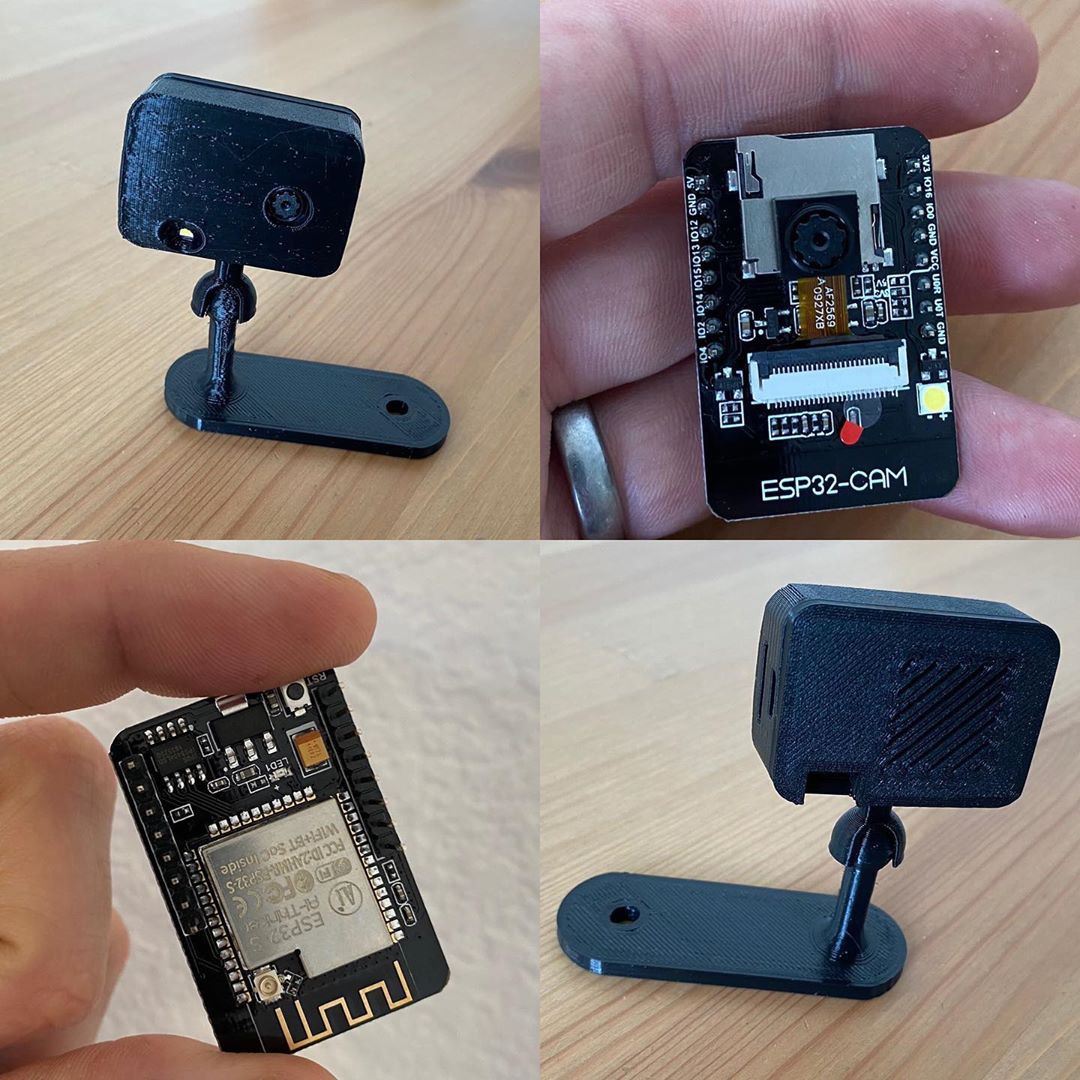
Wireless Camera
07/10/2020 at 12:14 • 0 comments![]()
Hi there, I am back with another great and interesting project that is a Wireless Camera out of ESP32. Like ESP8266, Esp32 is also a development board with on board Wi-Fi but it has a greater number of pins and some more features additional to the ESP8266 or NODEMCU. In this project we are using an ESP32 chip or metal casing one PCB which is present on development board a Camera Model and some 3-D printed parts. Along this we have also used a SD card module to save the recording on the SD card and also transmit live surveillance on the server which is coded on the ESP32. We have custom designed the PCB for the ESP32 camera along with SD card module. the circuits can be found on the internet and can be designed easily. We have also used a led to provide light in the dark conditions. This circuit on battery and hence it is very important to make it power saving. We have tried to make PCB as small as possible with all the necessary components. No USB to serial IC is given on the PCB as ESP32 can be programmed via its Rx and Tx pins provided. And then when the all the components are soldered, we closed the circuit in the 3-D Model. The PCB was ordered on NextPCB and they provided me the best quality in short time, which is satisfactory. Ordering PCB online in various sites are a step towards developing our own circuit. NextPCB provides very easy😎 and fast delivery🚚 of PCB in different masks and paste with professional look. Also, they send you the picture of your PCB before shipping it to you, Now that very exciting…😃😃👍. #arduino #arduinouno #arduinoproject #arduinomega #arduinonano #arduino duo #ESP32 #Camera Module
-
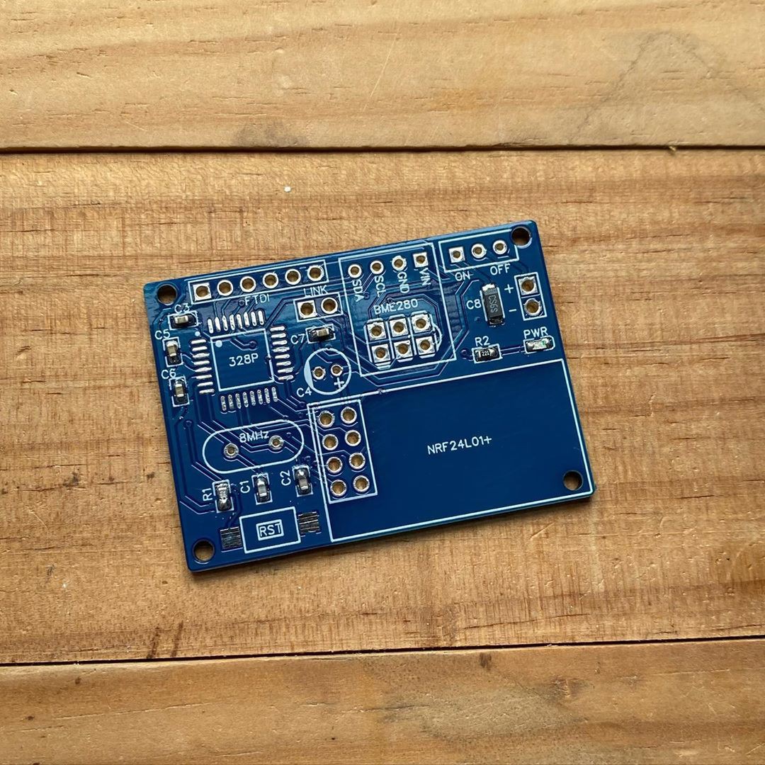
Wireless Humidity Tracker
07/10/2020 at 12:13 • 0 comments![]()
Hi friends, I am sharing another interesting topic in developing your circuits. The one which I am sharing with you is an NFR24L01 based circuit. The components used in this are an ATMEGA328P-AU, NFR24L01, Touch sensor and BME280 humidity sensor. For testing the circuits, the modules are best but for making a prototype these are very bulky so in this case we build a PCB especially for the task in this case this is the one. Mainly most of the modules are tried to be adjusted in it as the single piece but ATMEGA328P-AU circuit is made. No USB to Serial IC is designed in the PCB as a breakout for the FTDI connection is provide via which we can program ATMEGA328P-AU. NRF24L01 is a 1km range RF transmitter with the data rate of about 2Mbps, which is very good and useful solution for sending data via RF technology. BME280 is a Humidity sensor which provide accurate data of the water content in the air. Touch sensor provides a trigger for the circuit to send the data as it runs on battery and continuously running of circuit can drain the battery so it is good to trig the circuit on for the short amount of time and send the data. This would not be possible without the help of NextPCB and their extreme good and fast service of provide custom PCB on time. Ordering PCB online in various sites are a step towards developing our own circuit. NextPCB provides very easy😎 and fast delivery🚚 of PCB in different masks and paste with professional look. Also, they send you the picture of your PCB before shipping it to you, Now that very exciting…😃😃👍. #arduino #arduinouno #arduinoproject #arduinomega #arduinonano #arduino duo #NRF24L01 #BME280
-
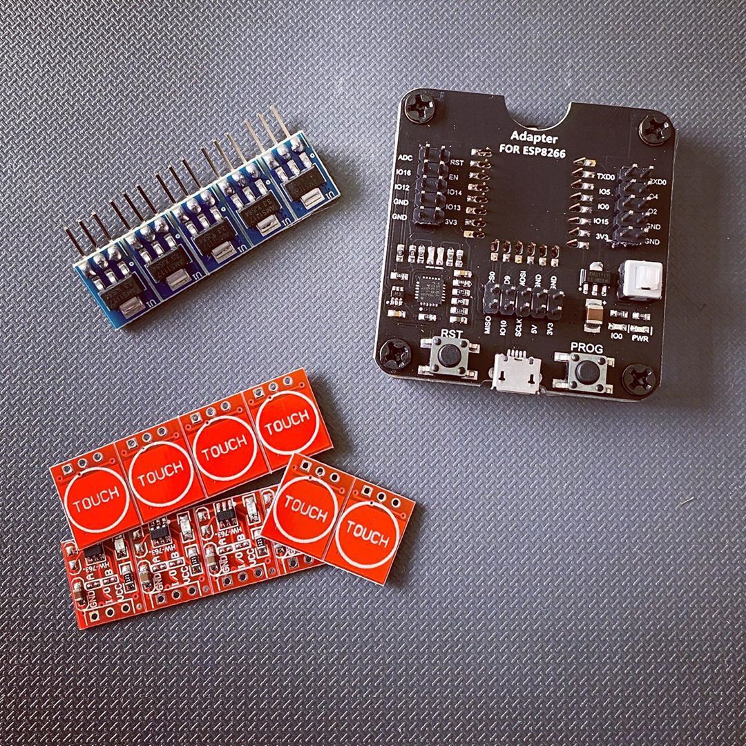
ESP8266 Touch Sensor
07/10/2020 at 12:12 • 0 comments![]() Hey guys, today I am going to discuss about some of the most useful IC, Development Boards and Sensor. One from each of them are AMS1117 3.3V regulator IC, ESP8266 Board (full complete with adapter) and Touch Sensor. So, let’s talk about each of them, as I have told earlier in my previous post about different type of IC packages this is of SOT-223. So, it is vit difficult to solder on a piece of perfbord as it is a SMD type, so dip converter is the best solution of this problem which I have discussed in my post. Next moving onto Touch sensor is built out of several smd components mainly consisting of TTP223 IC which is a Capacitive touch sensitive IC, it actually detects the voltage on the touch pad and monitors it. when we touch the capacitive touch pad a small amount of voltage drop is developed on the pin of the IC which is detected, and IC makes the output pin HIGH or active. Now it’s time for ESP8266, I am sure that many of us have done work on ESP8266 or NODEMCU but the whole development Board is not the ESP8266 but only the metal casing PCB is the ESP8266 Board. It consists of a WI-FI chip and an 4MB memory in very small smd package and left-over pc is the programming adapter which consist of USB to Serial converter IC like CH340G or some other like it. It also consists an additional button other than reset because as it is a Wi-Fi chip you can flash a custom Firmware onto it by pressing down the flash button and loading firmware onto it. So, this was the some of the important things which are used in most of the IOT projects. I hope you like it and NextPCB helped me out to make my Projects and good looking by developing PCB’s for my projects. Ordering PCB online in various sites are a step towards developing our own circuit. NextPCB provides very easy😎 and fast delivery🚚 of PCB in different masks and paste with professional look. Also, they send you the picture of your PCB before shipping it to you, Now that very exciting…😃😃👍. #arduino #arduinouno #arduinoproject #arduinomega #arduinonano #arduino duo #ESP8266 #NODEMCU
Hey guys, today I am going to discuss about some of the most useful IC, Development Boards and Sensor. One from each of them are AMS1117 3.3V regulator IC, ESP8266 Board (full complete with adapter) and Touch Sensor. So, let’s talk about each of them, as I have told earlier in my previous post about different type of IC packages this is of SOT-223. So, it is vit difficult to solder on a piece of perfbord as it is a SMD type, so dip converter is the best solution of this problem which I have discussed in my post. Next moving onto Touch sensor is built out of several smd components mainly consisting of TTP223 IC which is a Capacitive touch sensitive IC, it actually detects the voltage on the touch pad and monitors it. when we touch the capacitive touch pad a small amount of voltage drop is developed on the pin of the IC which is detected, and IC makes the output pin HIGH or active. Now it’s time for ESP8266, I am sure that many of us have done work on ESP8266 or NODEMCU but the whole development Board is not the ESP8266 but only the metal casing PCB is the ESP8266 Board. It consists of a WI-FI chip and an 4MB memory in very small smd package and left-over pc is the programming adapter which consist of USB to Serial converter IC like CH340G or some other like it. It also consists an additional button other than reset because as it is a Wi-Fi chip you can flash a custom Firmware onto it by pressing down the flash button and loading firmware onto it. So, this was the some of the important things which are used in most of the IOT projects. I hope you like it and NextPCB helped me out to make my Projects and good looking by developing PCB’s for my projects. Ordering PCB online in various sites are a step towards developing our own circuit. NextPCB provides very easy😎 and fast delivery🚚 of PCB in different masks and paste with professional look. Also, they send you the picture of your PCB before shipping it to you, Now that very exciting…😃😃👍. #arduino #arduinouno #arduinoproject #arduinomega #arduinonano #arduino duo #ESP8266 #NODEMCU -
SMD - DIP CONVERTERS
06/24/2020 at 17:17 • 0 comments![]()
Hi friends,we all know that the most important thing in any circuit is controllers or Integrated Circuits (IC’s). There are two types of it, Microcontroller and Microprocessors which I hope all of you know. All IC’s are built up in certain specified and certified dimensions which are accepted world-wide. These certified and specific dimensions are called PACKAGES. The most common out of all packages is the DIP-package, which is available for very common IC’s like 555, LM365, LM398, L293D, LM298, ATMEGA328P, ATMEGA8, etc. and many more. But there are some IC’s which are available only in Surface Mount Packages or SMD packages like QFN, SOP, TSOP, LQFP, TQFP, SOIC, etc. and many more but today we are here to discuss about some IC’s which are only available in SMD packages and not DIP for these type of the IC’s NEXT PCB provides a SMD to DIP converter PCB which can be easily used for prototyping or for BREADBOARD testing which is most important thing while making a project and you don’t know complete idea about its circuit. Like we all have used and familiar with Arduino Boards, the IC’s used in it is ATMEGA328P-PU please read carefully the complete IC name but Arduino nano has ATMEGA328P-AU the difference between these two is not very big but no so small also because UNO(Atmega328p-pu) has 6 Analog Pins whereas NANO(Atmega328p-au) has 8 Analog Pins also IC’s like FT232RL,CH340G, ATMEGA16U2, ATMEGA32U2 are some of the useful IC but these are not available in DIP package hence we cannot test them on Breadboard. So NextPCB has given a solution to it by providing SMD to DIP Converter Packages PCB which are provided as open source. Here they have used an ATMEGA328P-AU IC and attached a reset button to it on the PCB rest all the pins are available of the dip outputs, along with XI, XO RESET(Pull-up) so that we can program them by using any USB to TTL programmer like FT232RL. Designing a PCB is fun but when after coming of them we see some error in our schematics we get frustrated so, according to me this is the best solution for these types of IC’s and we should really make use of it. Ordering PCB online in various sites are a step towards developing our own circuit. NextPCB provides very easy😎 and fast delivery🚚 of PCB in different masks and paste with professional look. Also, they send you the picture of your PCB before shipping it to you, Now that very exciting…😃😃👍. #arduino #arduinouno #arduinoproject #arduinomega #arduinonano #arduino duo
-
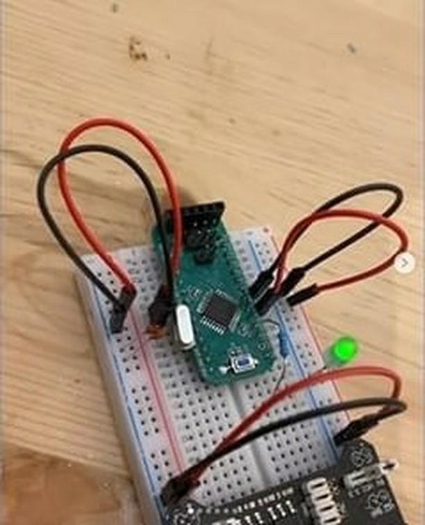
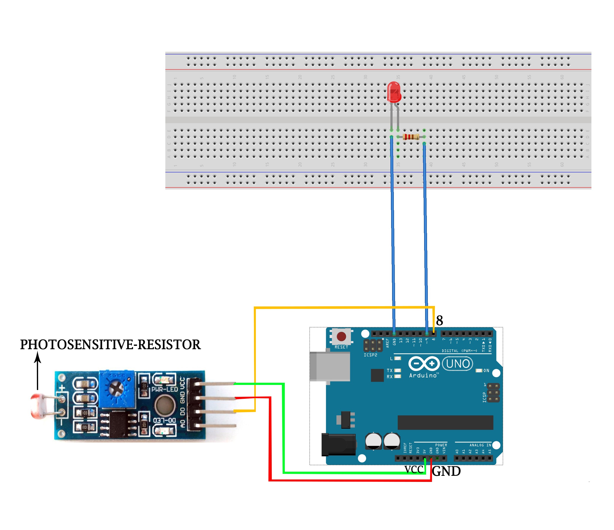
LDR SENSOR
02/29/2020 at 18:27 • 0 commentsLDR SENSOR:-
![]()
![]()
INTRODUCTION:-
LDR sensor is a type of resistor is variable and dependent on light of the surroundings. You can see these types of sensors in smart lights street lights and various other electronic gadgets which work in day time or in night or according to the light of the surrounding. These types of sensors are easy to operate and can easily be programmed to get output.
As this sensor is sensitive of small amount of light also it is used in various devices which are light sensitive. The sensor is very simple cheap and the basic one available in the market.
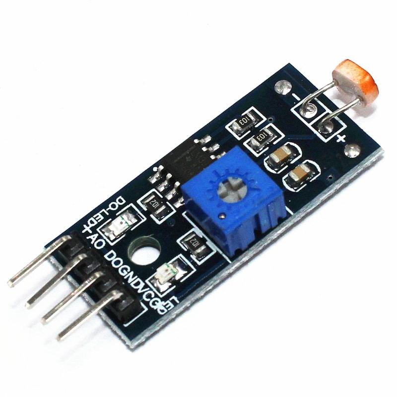
DESCRIPTION:-
LDR sensor is a sensor which is built out of LM393 ic a Light-Dependent-Resistor a variable resistor to trim the values of range of the value given by the sensor to the microcontroller.
Sensor also has an onboard Power led and an onboard Status led which will glow up whenever the sensor senses the light more than the threshold value.
Light-Dependent-Resistor is a type of Resistor which is dependent on the light coming from the surrounding to give the values. It senses the light around it and then sends the signal to the microcontroller.
*NOTE:- AS THIS SENSOR IS A TYPE OF RESISTOR THEN THERE IS A CHANCE OF CERTAIN VARITIONS IN THE VALUES.
This sensor gives the output of DIGITAL and ANALOG type. Difference b/w analog and digital signal is that in the digital signal only high state or low state is given but in the analog signal values b/w 0-1023 is given which is more suitable for condition in the code.
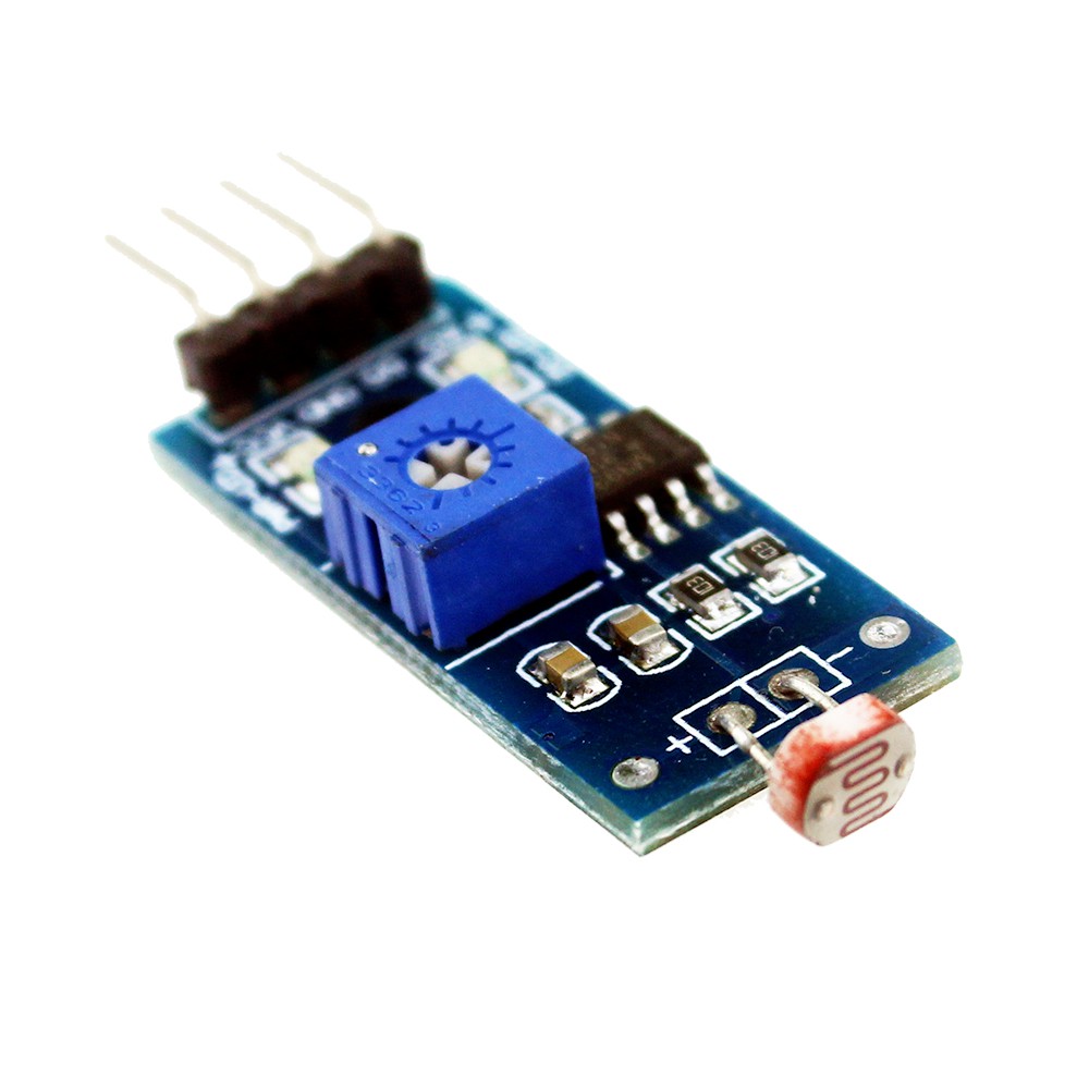
SENSOR SPECIFICATIONS:-
![]()
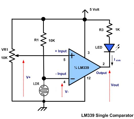
SCHEMATIC DIAGRAM:-
![]()
FEATURES AND APPLICATIONS:-
- Light sensitivity is high
- Easy to use
- Adjustable value
- Low price
NOTE:- AS SENSOR IS AMLL SO USE IT CAREFULLY
- Used in smart street lights
- Phones
COMPONENTS NEEDED:-
- Any microcontroller preferably Arduino Uno for beginners.
- A led
- A LDR sensor
- A breadboard
- Jumper wires
- 1kohm resistor
CIRCUIT DIAGRAM:-
![]()
First take the power lines onto the bread board from microcontroller
VCC/5v-->+ line and GND--> - line.
Then connect the sensor on to the bread board and connect power to the sensor from powerlines using jumper wires.
Now connect D0 PIN OF SENSOR TO DIGITAL(PIN 2) OF THE MICROCONTROLLER and AND A0 PIN TO THE A0 PIN OF THE MICROCONTROLLER.
Connect an led to the digital pin 3 of the microcontroller
CODE:-
//put this code in the ide of arduino from this line
//this for digital value
int ldrsensor=2; // initializing the digital pin
int led=3;
int value;
void setup(){
Serial.begin(9600);
pinMode(ldrsensor, INPUT);
pinMode(led, OUTPUT);
}
void loop(){
value=digitalRead(ldrsensor); // reading the digital dat from the sensor
digitalWrite(led, value); // switching buzzer on or off
}
//put this code in the ide of arduino from this line
//note:- this code is for analog value
int ldrsensor=A0; //initializing the analog pin
int led=3; // initializing buzzer pin
int value;
void setup(){
Serial.begin(9600);
pinMode(ldrsensor, INPUT); // assing the pin mode type of the pin as input or output
pinMode(led, OUTPUT);
}
void loop(){
value=analogRead(ldrsensor); //reading the valus from the sensor
value=map(value,0,1023,0,255); // mapping the value from 0 to 1023 b/w 0 to 255
digitalWrite(led, value); //
}
WORKING:-
As the code starts it initializes the pin to which the LDR sensor is connected. As soon as the light dependent changes its resistance from one value to another it send its data then the microcontroller. Then according to the condition in the code the microcontroller turn led on or off.
PCB DESIGNING:-
![]()
![]()
![]()
Now we have got the PCB design and it’s time to order the PCB’s. For that, you just have to go to JLCPCB.com, and click on “QUOTE NOW” button.
JLCPCB...
Read more -
TEMPERATURE SENSOR
02/29/2020 at 18:21 • 0 commentsTEMPREATURE SENSOR:-
![]()
![]()
INTRODUCTION:-
Thermistor Temperature sensor is a type of resistor is variable and dependent on temperature of the surroundings. You can see these types of sensors in power banks various electronic devices which is meant for certain temp range and to detect and work according to it. These are easy to use and can be hooked up to any microcontroller to get the desired output.
As these are small and easy to fit at any place so it is very common and used among the people .I am also using this one as it is easy to connect and the output is also simple.it is very basic one and easily available in market.
DESCRIPTION:-
Thermistor temperature sensor is a sensor which is built out of LM393 ic a Thermo-Resistor a variable resistor to trim the values of range of the value given by the sensor to the microcontroller.
Sensor also has an onboard Power led and an onboard Status led which will glow up whenever the sensor senses the temperature more than the threshold value.
Thermo-Resistor is a type of Resistor which is dependent on the temperature of the surrounding to give the values. It senses the environment temperature and then sends the signal to the microcontroller.
*NOTE:- AS THIS SENSOR IS A TYPE OF RESISTOR THEN THERE IS A CHANCE OF CERTAIN VARITIONS IN THE VALUES.
This sensor gives the output of DIGITAL and ANALOG type. Difference b/w analog and digital signal is that in the digital signal only high state or low state is given but in the analog signal values b/w 0-1023 is given which is more suitable for condition in the code.
SCHEMATIC DIAGRAM:-
![]()
FEATURES AND APPLICATIONS:-
- Temperature sensitivity is high
- Easy to use
- Adjustable value
- Low price
NOTE:- AS SENSOR IS AMLL SO USE IT CAREFULLY
- Used in powerbanks
- Laptops
- Induction stoves
COMPONENTS NEEDED:-
- Any microcontroller preferably Arduino Uno for beginners.
- A led
- A Thermistor Tempreature sensor
- A breadboard
- Jumper wires
- 1kohm resistor
CIRCUIT DIAGRAM:-
![]()
First take the power lines onto the bread board from microcontroller
VCC/5v-->+ line and GND--> - line.
Then connect the sensor on to the bread board and connect power to the sensor from powerlines using jumper wires.
Now connect D0 PIN OF SENSOR TO DIGITAL(PIN 2) OF THE MICROCONTROLLER and AND A0 PIN TO THE A0 PIN OF THE MICROCONTROLLER.
Connect an led to the digital pin 3 of the microcontroller
CODE:-
//put this code in the ide of arduino from this line
//this for digital value
int tempsensor=2; // initializing the digital pin
int led=3;
int value;
void setup(){
Serial.begin(9600);
pinMode(tempsensor, INPUT);
pinMode(led, OUTPUT);
}
void loop(){
value=digitalRead(tempsensor); // reading the digital dat from the sensor
digitalWrite(led, value); // switching buzzer on or off
}
//put this code in the ide of arduino from this line
//note:- this code is for analog value
int tempsensor=A0; //initializing the analog pin
int led=3; // initializing buzzer pin
int value;
void setup(){
Serial.begin(9600);
pinMode(tempsensor, INPUT); // assing the pin mode type of the pin as input or output
pinMode(led, OUTPUT);
}
void loop(){
value=analogRead(tempsensor); //reading the valus from the sensor
value=map(value,0,1023,0,255); // mapping the value from 0 to 1023 b/w 0 to 255
digitalWrite(led, value); //
}
WORKING:-
As the code starts it initializes the pin to which the temperature sensor is connected. As soon as the termo-resistor changes its resistance from one value to another it send its data then the microcontroller. Then according to the condition in the code the microcontroller turn led on or off.
PCB DESIGNING:-
![]()
![]()
![]()
Now we have got the PCB design and it’s time to order the PCB’s. For that, you just have to go to JLCPCB.com, and click on “QUOTE NOW” button....
Read more -
JOYSTICK WITH ARDUINO
02/22/2020 at 15:22 • 0 commentsJOYSTICK:-
![]()
INTRODUCTION:-
Analog Joystick is not any type but it is a type of switch or simple components attached or joined together to form a Joystick. It is not as same as most of you might have an Xbox one or some gamepad controller, it is similar to that bot can’t say exactly that. These types of joystick are very basic one and easily available and are used in variety of projects for making moveable pointers like mouse.
We can combine few more components with this joystick to make our own gamepad controller, that will be discussed in the future post. There are better working and more advanced versions of it the one which I am using is easily available and easy to use as always.
DESCRIPTION:-
Analog Joystick is a combination of two 10 k potentiometer or variable resistor. It is not built out of any IC (integrated circuit’s) but only two pot for X & Y axis and a pus button for selection.
It has only 5 pin out of which two are analog output, 1 digital or analog output and two power inlets.
*NOTE:- THIS SENSOR IS NOT THE BEST ONE TO USE FOR PROFESSIONAL THINGS , IT CAN ONLY BE USED TO MAKE SOME SAMLL PROJECTS.
This sensor gives the output of both type ANALOG and DIGITAL. Difference b/w analog and digital signal is that in the digital signal only high state or low state is given but in the analog signal values b/w 0-1023 is given which is more suitable for condition in the code. The axis coordinates or the analog values are given in values between 0-1023 and pushbutton can be used to give output of both analog and digital type.
FEATURES AND APPLICATIONS:-
- Easy to use
- Adjustable value
- Both type of signal out is available
- Low price
- JOYSTICKS
- Motor control
- Mouse pointer using mouse library
SENSOR SPECIFICATIONS:-
![]()
COMPONENTS NEEDED:-
- Any microcontroller preferably Arduino Uno for beginners.
- A led
- A JOYSTICK
- A breadboard
- Jumper wires
- 1kohm resistor
CIRCUIT DIAGRAM:-
First take the power lines onto the bread board from microcontroller
VCC/5v-->+ line and GND--> - line.
Then connect the sensor on to the bread board and connect power to the JOYSTICK from powerlines using male to female jumper wires.
Now connect VRx PIN OF JOYSTICK TO MICROCONTROLLER ANALOG PIN A0 and VRy PIN OF THE JOYSTICK TO THE MICROCONTROLLER ANALOG PIN A1, SW PIN OF JOYSTICK TO DIGITAL (PIN 2) OF THE MICROCONTROLLER.
Now connect two leds to the breadboard – to gnd and + to digital pin 3 and 4 of the microcontroller.
CODE:-
//put this code in the ide of arduino from this line
int xaxis=A0; //initializing the analog pin for VRx
int yaxis=A1; //initializing the analog pin for VRy
int led1=A2; // initializing led pin for VRx
int led1=A3; // initializing led pin for VRy
int value1;
int value2;
void setup(){
Serial.begin(9600);
pinMode(xaxis, INPUT); // assign the pin mode type of the pin as input or output
pinMode(yaxis, INPUT); // assign the pin mode type of the pin as input or output
pinMode(led1, OUTPUT);
pinMode(led2, OUTPUT);
}
void loop(){
value1=analogRead(xaxis); //reading the values from the JOYSTICK
value2=analogRead(yaxis); //reading the values from the JOYSTICK
analogWrite(xaxis, value1);
analogWrite(yaxis, value2);
}
WORKING:-
As the code starts it initializes the pin to which the JOYSTICK send the coordinated to the microcontroller. On receiving the analog signal the microcontroller send these values to the analog pin 2 and 3 to glow the led according to the analog value
PCB DESIGNING:-
![]()
![]()
![]()
Now we have got the PCB design and it’s time to order the PCB’s. For that, you just have to go to JLCPCB.com, and click on “QUOTE NOW” button.
JLCPCB are also sponsor of this project. JLCPCB (ShenzhenJLC Electronics Co., Ltd.), is the largest PCB prototype enterprise in Chinaand a high-tech manufacturer...
Read more


 Hey guys, today I am going to discuss about some of the most useful IC, Development Boards and Sensor. One from each of them are AMS1117 3.3V regulator IC, ESP8266 Board (full complete with adapter) and Touch Sensor. So, let’s talk about each of them, as I have told earlier in my previous post about different type of IC packages this is of SOT-223. So, it is vit difficult to solder on a piece of perfbord as it is a SMD type, so dip converter is the best solution of this problem which I have discussed in my post. Next moving onto Touch sensor is built out of several smd components mainly consisting of TTP223 IC which is a Capacitive touch sensitive IC, it actually detects the voltage on the touch pad and monitors it. when we touch the capacitive touch pad a small amount of voltage drop is developed on the pin of the IC which is detected, and IC makes the output pin HIGH or active. Now it’s time for ESP8266, I am sure that many of us have done work on ESP8266 or NODEMCU but the whole development Board is not the ESP8266 but only the metal casing PCB is the ESP8266 Board. It consists of a WI-FI chip and an 4MB memory in very small smd package and left-over pc is the programming adapter which consist of USB to Serial converter IC like CH340G or some other like it. It also consists an additional button other than reset because as it is a Wi-Fi chip you can flash a custom Firmware onto it by pressing down the flash button and loading firmware onto it. So, this was the some of the important things which are used in most of the IOT projects. I hope you like it and NextPCB helped me out to make my Projects and good looking by developing PCB’s for my projects. Ordering PCB online in various sites are a step towards developing our own circuit. NextPCB provides very easy😎 and fast delivery🚚 of PCB in different masks and paste with professional look. Also, they send you the picture of your PCB before shipping it to you, Now that very exciting…😃😃👍. #arduino #arduinouno #arduinoproject #arduinomega #arduinonano #arduino duo #ESP8266 #NODEMCU