 JRodrigo
Specifications:
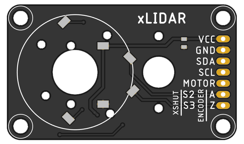
- 3 x VL53L0X - Time-of-Flight ranging sensor
- On board incremental encoder with XSHUT signals for on start setup.
- ...
Affordable and open-source LiDAR based on 3x VL53L0X ranging sensor
Already have an account? Log in.
To make the experience fit your profile, pick a username and tell us what interests you.
Specifications:
- 3 x VL53L0X - Time-of-Flight ranging sensor
- On board incremental encoder with XSHUT signals for on start setup.
- ...
When I tested the prototype, as I already expected, it was impossible to maintain a stable communication via I2C when the rotor turns around.
The positive part is that the power via "SD pins" was stable with some capacitors, maybe using a couple more of SD pins gets a more stable voltage.
For the first board design I opted for a basic design, like a breakout board. Once the prototype works correctly. But in the future the best option is to integrate a microcontroller to get the measurement and control the motor speed, obtaining this data via I2C, SPI, ...
It's just a board with a MOSFET to control the motor speed and a pin header for the signals. To carry the rotor signals (VCC,GND,SDA,SCL,XSHUNT+ENCODER) I'm going to use the pins from a SD card slot.


JRodrigo,
It really helps if you have specific application(s) in mind. These are general purpose tools, but to really get outstanding results, you need to work one or a few very specific ideas. So, can you put parts together? Yes. Can you make those components gather the data you need to interpret a situation, measure something, provide critical data to a controller?
Now I could not easily find the technical information on the key performance and application parameters for these devices. I could not easily understand the breakout boards and things for sale. The various development environments are almost pure chaos. And I have a pretty good technical and scientific backgroud. If I had time, I could build one from scratch. But I do not have time.
If you look at the world that uses or wants to use "lidar", you can google "lidar" and think about and try to profile the 46.8 million pages that mention it. "lidar" "3d" cuts that down to 15.1 million.
Now I have a few ongoing requirements that lidar might be useful for. There is need for pre-scanning the air composition and turbulence in front of aircraft, for both safety and fuel optimization. In advanced craft design, the area around each surface element is scanned to optimize flow, often using lasers to modify flow at critical points. There is need for 2D and 3D scanning the interior and boundaries of chemical plants, refineries, power plants and other emissions sources to quantify and map chemical emissions. There are many surface and scene mapping needs, Lidar might be adaptable to monitoring changes in the gravitational field.
What is common to all of them, is not the technical details or the simple functionality or the device; but, rather the data and use of the data. The people with needs and requirements for sensors want the data so they can do something. So you might want to spend some time just thinking about what data this device provides and who might want to use it. Is it providing some analog data streams that you can tap? Those can be amplified, fed to ADCs and become useful in their own right. Often the analog sensors in these low cost device, coupled to fairly standard amplfiers and ADCs, can give you data streams not envisioned by the part manufacturer.
I have no idea why you wanted to do this. If you carefully search your mind, and heart, there must be something you want to do, and this was just a tiny step you felt you could take. Or you just randomly picked some components to play with for learning. I do not know. Perhaps you do not know.
I have to spend time, sometimes days or weeks or even decades, constantly reviewing why I think some technology is important - to me, and to society. I investigate things deeply on the Internet. I might spend ten or twenty hours at one sitting, on one idea, just to see what thousands of pages of mentions might tell me. I build mathematical statistical models of many things, to play with tradeoffs and possibilities. On this "light" radar, I would certainly look through all the frequencies, from yoctoHertz to yottaHertz. And definitely would not forget acoustic and gravitational applications. And all the power levels from yoctoWatts to yottaWatts, and the associated intensities, field strengths, gradients, acceleration fields and noise sources.
My impression is the that chemical, spectroscopic applications of time of flight methods have only scratched the surface of what is possible. I can see supermarket freshness sensors, people trackers, biolab applications, food processing plant applications, and thousands more.
Also, can you have arrays of these fabricated to specifications? The time of flight cameras are simply arrays of sensors. If you control each pixel of the reception, you can use a smaller number of illuminators. If you use random placement, but can determine location and orientation precisely, you can use fairly standard mathematics to gather statistically unbiased estimates of things that are hard to gather with fixed regular arrays.
If you have not, you should check the literature on "lensless" methods. They are a good complement.
Perhaps you could start by looking over all the mentions of lidar in Hackaday,io by googling site:"hackaday.io" "lidar" for 1880 mentions right now, or site:"hackaday.io" "time of flight" for 280 mentions just now. You can spend a lot of time trying to build one fairly useless (?) piece of equipment, or you can try to help the large community of people understand your area of interest better. Between those extremes, you can learn a lot by simply going through what has been done, noting equipment, parts, applications, and data provided.
Finally, you titled this "affordable" and "open source", so I think you had in mind working within a community of people working on this technology and the related applications.
Best wishes,
Richard Collins, The Internet Foundation

i have used VL53L0X for several years now and tried something similar to this.
The beam is a 15 degree cone not a straight beam and angled reads can jump all over. At 2 meters the beam is 12 inches wide Think of the angle, sometimes the average is to the edge and others to the center of the beam so the distance read varies by as much as 45mm.
Multiple reads at every angle and put the group thru a pass filter really help tighten accuracy.
Your issues may not be all contact noise.

I've used them also, many laid out in different directions, but i'm thinking if a pinhole or lens could narrow the beam...?

i think ive seen a millitary version of somthing like this it had to be towed by a car ...love it! greatwork guys..i was trying to get my head round kinect doing somthing like this
hi
Im a newbie on hackaday and certainly limited electronics expeience- this project interests me a lot but you do not say what the intended application is. Is this for collision avoidance or could it be applied to aerial mapping and terrain analysis which is my interest? Have you seen the pcb motor project (https://pcbmotor.com/) it seems ideally suited for this application or at least worth considering..

You could use a slip ring to bring the signals from the rotating sensors to the board: https://www.ebay.com/itm/12-5mm-12-Circuits-Capsule-Compact-Tiny-Slip-Ring-250Rpm-2A-250V-Test-Equip-ED/112240145761

I love the concept.
It occurs to me that if the traces and and SD card spring contacts turn out to be a weak point, they could be avoided by using wires then running the disk for 1 revolution, then running in reverse direction for 1 revolution, and so on. Just reverse disk turning direction every revolution.
That way the disk never twists up the wires too much, but it's not that much more complicated to interpret the data; it's still very what-you-see-is-what-you-get.
you could technically make the movement like a windscreen wiper movement, piston movement etc to achieve that, that way you dont have to contend with back emf from changing motor direction.

I see the tracks as a weak point of this design. You could use magnetic coupling to transmit power (and even data), and optical down the center pivot to transmit data. Just a thought.

I have seen magnetic coupling for the head signals on an old VCR head. I would put a wireless module e.g. ESP8266 to talk to the sensor and send out the data on WiFi.

Nice idea & design! Be wary that VL53L0X isn't an analog sensor that you can run at any speed, it has various speed limitations such as how it is only expected to update the data at around 30 times per second, and it spends about 20ms for the distance ranging where it's expected that the distance won't have changed much. So realistically, you can probably only rotate your sensor at very slow speeds (I'm guessing just once per second). You might be better off building a PCB with 20 x VL53L0X sensors (the raw sensor can be affordable if you shop around) that doesn't move. Anyway, I'm sure your current design is good enough for some purposes even if it moves slowly. I hope it goes well!

Why three sensors, and not one or two or four or five or more? Is there a sampling limitation which dictates how many sensors are required? Maybe something to do with beam width at different ranges? What is the vertical resolution, same as horizontal beam width?

arguably the easiest geometry to work with in terms of calibration
because you’d need to have a different photoreceiver
Not really. Think of a polygonal mirror and 3 sensors around it. I think you need a hexagonal mirror to avoid overlap as the mirror doubles the scan angle.
There is a problem with dead zones, where the sensors block the light path when they look a t 90° on the mirror. So perhaps some overlap could be good, like using a square mirror. Or you tilt the sensors slightly upwards, so they don't see themselves. But then your sensing rays are titled upwards also, except you use a pyramidal mirror (upside down truncated pyramid) instead of a prismatic mirror.

A mirror may also be expensive depending on the wavelength and if partly reflections of the glass surface may distort your measurements...
What about oscillating the Sensor-PCB by (Angle = 360 / Sensors) instead of rotating it? Then you could use cables instead.
With an L-shaped PCB, you control 4 sensors one on each side of the PCBs. This results in 90 degrees oscillation angle.
Also instead of an octagon, you could also stack 2 L-shaped PCBs. with 45 degrees shift. Depending on your tools, this may be easier.
 Ruediger F. Loeckenhoff
 Nolan Moore
 Alvaro Ferrán Cifuentes
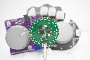
 Ahmed Oyenuga
would just like to say this is a really cool idea would love to find out if it could be integrated into a hand held 3d scanner one day :)