Close
0%
0%

Arduino Tester

I started making my own Arduino(UNO)-compatible boards, and felt the need for an "automated" tester for it. I then came up with a shield!!!

Similar projects worth following
I started designing and producing my own version Arduino-UNO compatible boards, and felt the need for a more automated (quick, easy) hardware test bed. I had some Freetronics-made yellow shield PCB's, and decided to make my Arduino tester entirely fit it.
Now, by "testing" my Arduino-compatible board I mean making sure these things work:

- Serial communication (Pins 0 and 1 of UNO)
- i2C (pins A4 and A5)
- Analog inputs
- PWM
- Digital inputs
- Digital outputs
- Reset button/function
- 5V regulator current capability (this is "coming soon")

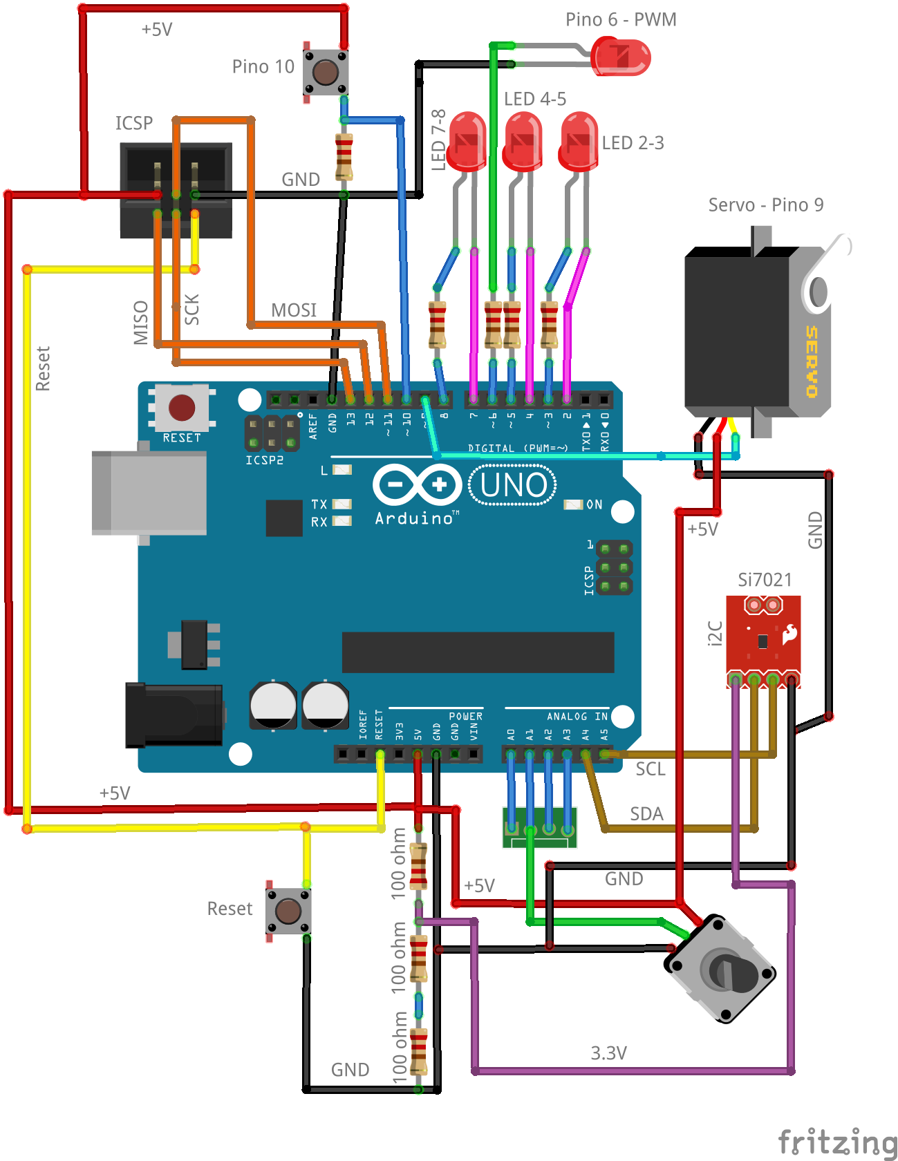
I came up with a nice (from my own standpoint) circuit arrange that tester each and every pin of my Arduino-compatible board:

- Pins 0 and 1 = Serial communication with a PC, through the "Serial.print()" command

- Pins 2 and 3= an LED connected between them

- Pins 4 and 5= another LED connected between them

- Pins 7 and 8= a third LED connected between them

- Pin 6= PWM test using a single LED + resistor

- Pin 9= connected to a 9G micro-servo-motor

- Pin 10= connected to a push-button

- Pins 11, 12 and 13= tested during bootloader burning to the ATMEGA328P-PU

- Pins A0..A3= a single potentiometer that can be "hardware-jumpered" to one analog input at a time.

- i2C communication on pins A4 and A5= an Si7021 temp+humidity breakout board.

In order to look at analog input and i2C data I have made an sketch for the Arduino under test: simply reading temperature and humidity from the Si7021, as well as analog voltage from A0..A3 and sending it over Serial port to the Arduino IDE serial console.

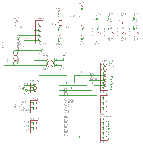
Here is a snapshot of the schematic diagram for this shield; note that you can download the full Eagle-CAD file from my GitHub, linked in the left-side of this page:

Here is a video of the system working:

  • 5 × Resistor 1k ohm 11/4W 5% resistor
  • 4 × LED 5mm LED (any color)
  • 1 × Tactile switch TH 5x5mm tactile switch
  • 1 × Potentiometer 10k ohm
  • 1 × Temp/humidity sensor Si702 i2C breakout board

View all 8 components

  • Schematic diagram made in Fritzing

    Clovis Fritzen03/29/2016 at 17:56 0 comments

    Hey guys, I just made a Fritzing-based schematic diagram for the Arduino tester shield; it makes it easier to see and differenciate all connections and components:

  • The idea, the making and more (a-less)

    Clovis Fritzen03/26/2016 at 04:38 0 comments

    For this first log I would like to point that I have already made this "product" work; it is sitting in the bench right now pumping i2C and analog input data through the ATMEGA328 serial port.

    My inspiration to create this tester came from a recent "desk of ladyada" series of videos featuring/advertising their proudly home-made testers for the Feather board series:

    I have worked in the electronics assembly industry for years, and know how outdated and slow are the current board testers out there; this is why I value and appreciate Ladyada's efforts and willingness to share info on their home-mad raspbery-pi based modern testers.

View all 2 project logs

Enjoy this project?

Share

Discussions

K.C. Lee wrote 03/26/2016 at 04:52 point

Usually for testing a system, you connect pins together for external loopack.  When you toggle a pin, another I/O that it is connected to would try to look at the logic level to see if it matches.  You can tests out if the I/O is stuck at logic '0'/'1' or floats.  The internal peripherals e.g. PWM do not get damages as easily, but you can use a RC and ADC to confirm that the duty cycle can affect the output.  This can be automated and report back errors.

https://www.eventhelix.com/RealtimeMantra/FaultHandling/hardware_diagnostics.htm

  Are you sure? yes | no

Clovis Fritzen wrote 03/26/2016 at 05:17 point

Hi, and thank you for the comment and ideas. Yes, for sure I am not doing it "the industrial way", and could further automate it to look like that, but the idea here is to have an "at-least-I-have-something" kind of system, so that is makes it easier to test my boards.

  Are you sure? yes | no

Similar Projects

Does this project spark your interest?

Become a member to follow this project and never miss any updates