 esben rossel
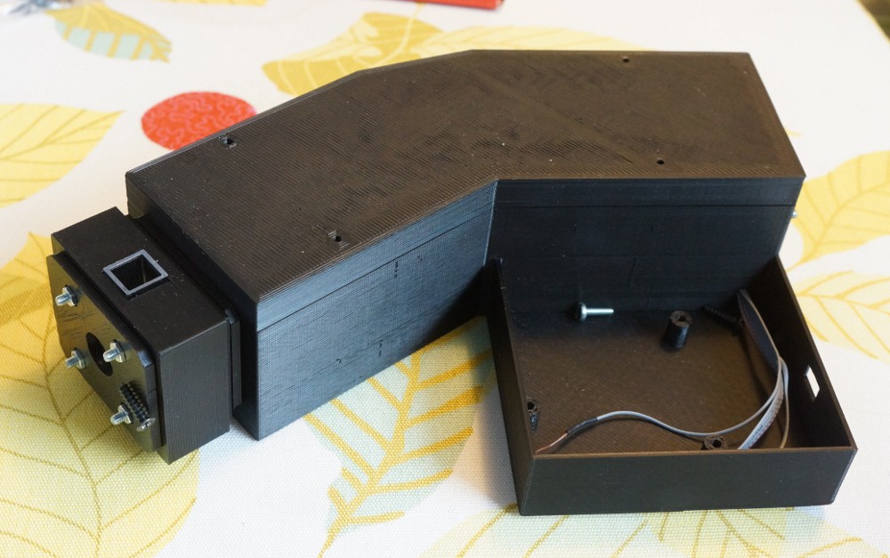
The OtterVIS LGL is a super cheap decently resolving entirely 3D-printable open source DIY spectrophotometer.
I've aimed at keeping costs low and quality high.
The OtterVIS LGL spectrograph is a lens-grating-lens design.
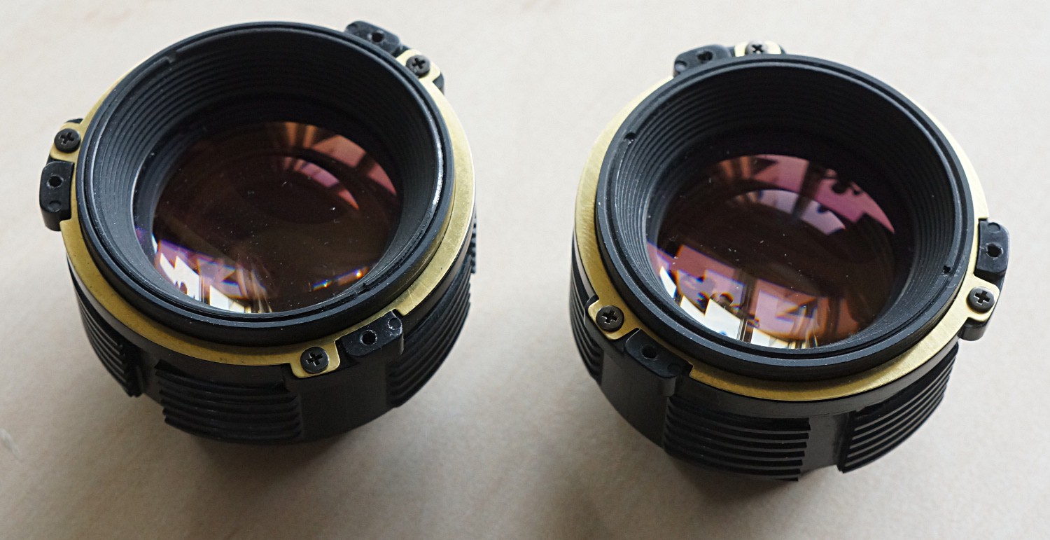
The lenses are two manual 50mm standard camera lenses. Most modern (modern as in post-1970) standard lenses are excellent performers, and because they were "standard" in their time, they are plentiful and cheap today. Cheaper even than simple spherical lenses.
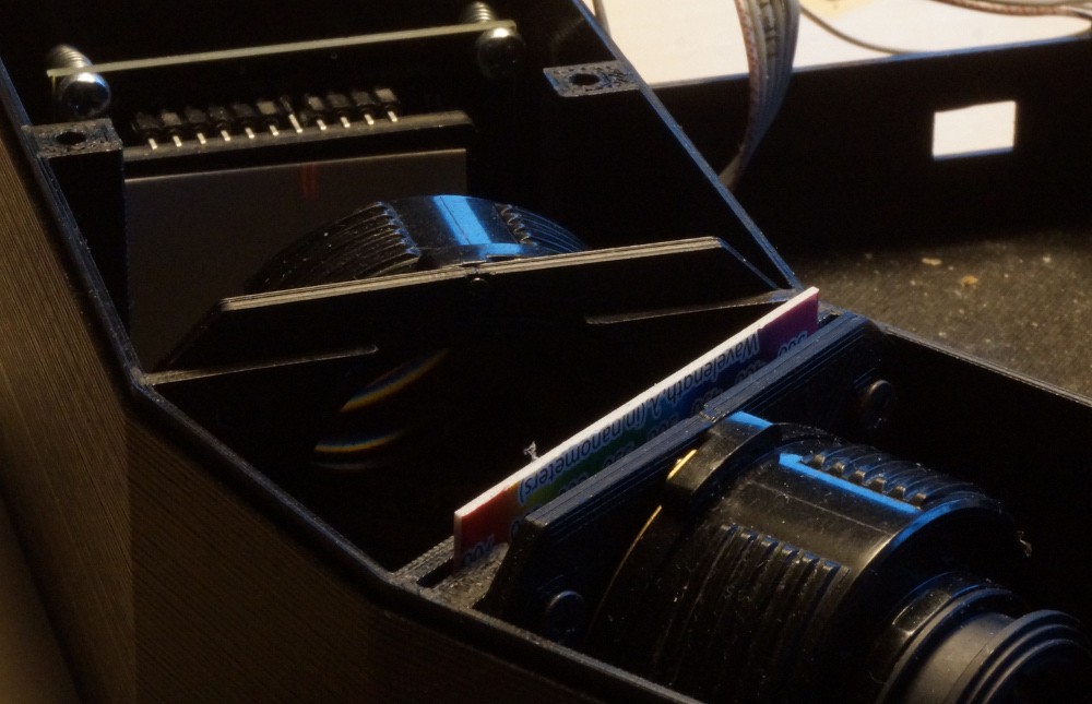
The grating is probably the weak link, as I went with a very cheap diffraction grating slide as opposed to a proper transmission grating. Still I believe it's better than a DVD.
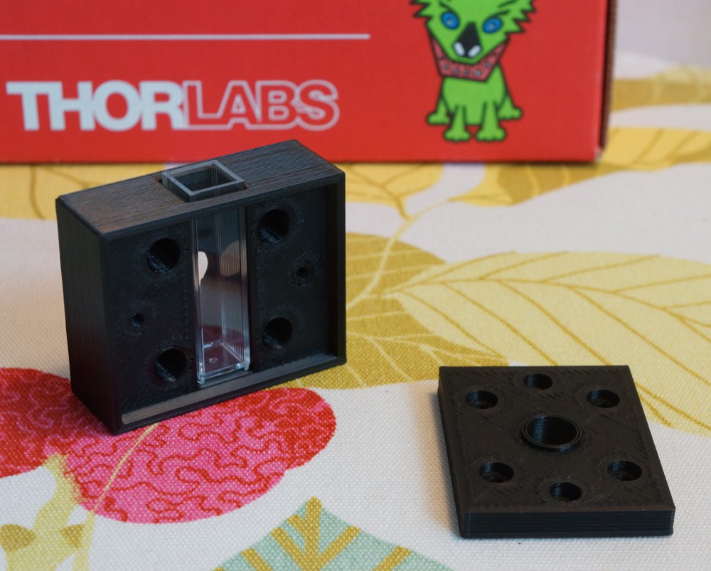
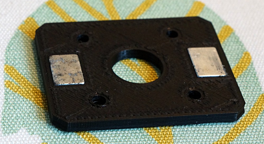
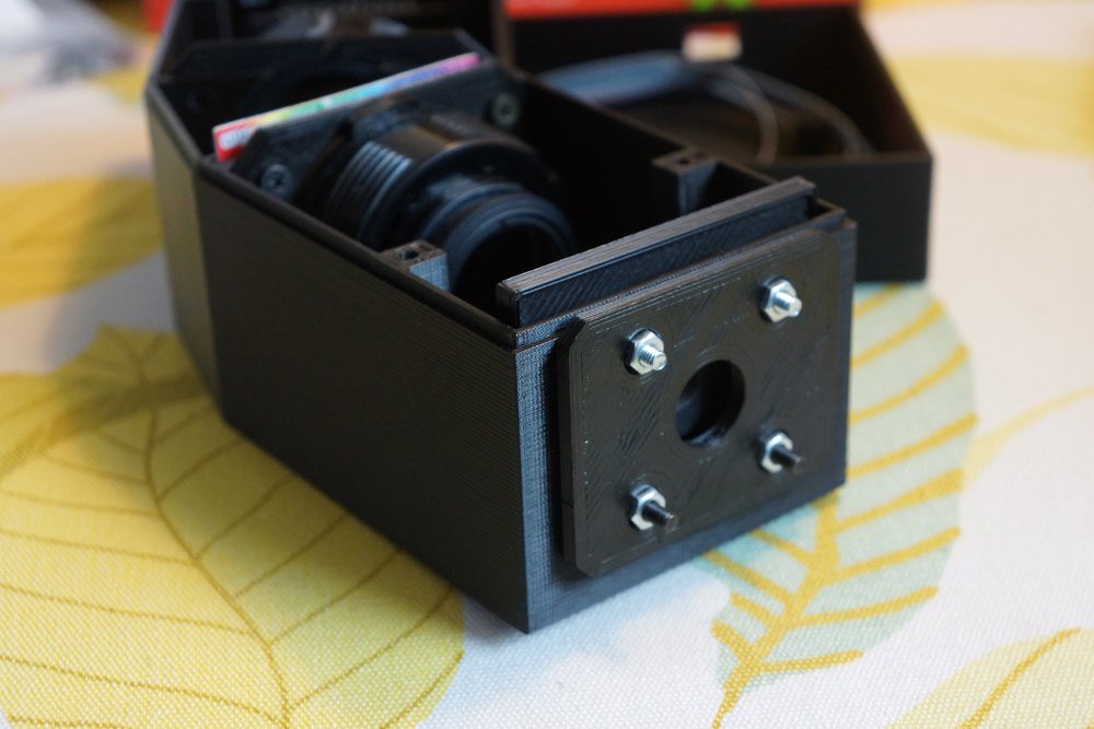
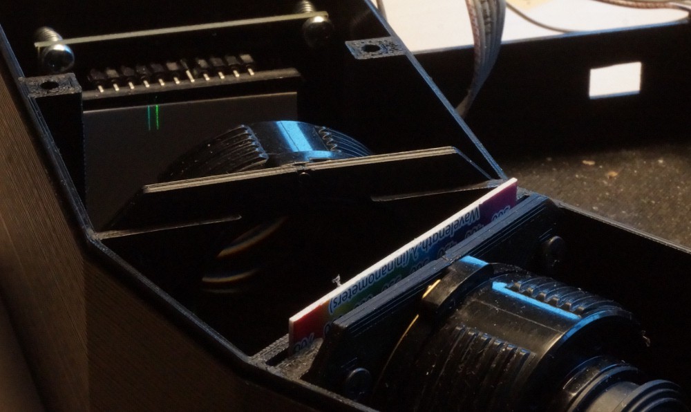
The slit is comprised of to razor blades mounted on a ring magnet stolen from my girlfriends refrigerator magnet collection.
Principles of operation:
The diagram for the spectrograph is as follows:
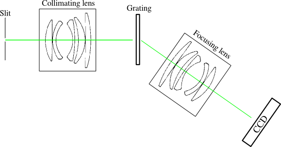
The first lens collimates the light from the slit. The second lens focuses the diffracted light onto the CCD.
The general diffraction equation is:
Which for first order diffraction (m=1) with an angle of incidence of 0° (the grating is normal to the collimating lens) reduces to:
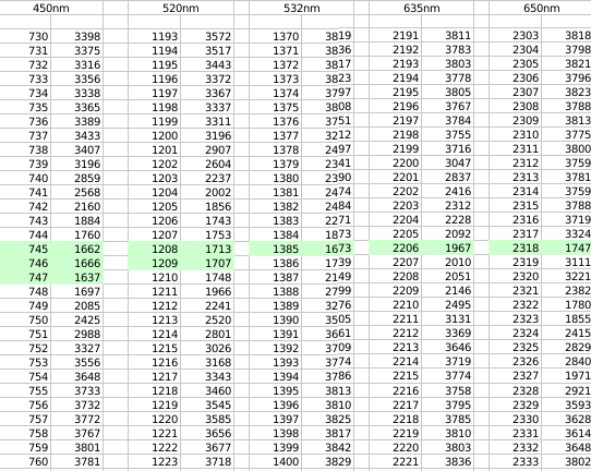
The grating constant is 1000 lp/mm and the lower wavelength is chosen to be 380 nm as the lenses start absorbing here. From 760 nm second order diffraction starts to overlap so 760 nm is chosen as the upper limit for the spectrum.
Inserting these values into the diffraction equation gives angles of diffracted light from 22.3°-49.5°. The center angle is 35.9°.
The CCD (TCD1304) is 29.1 mm long and and with a bit of trigonometry we end up with an ideal focal length of 60mm for the focusing lens. A bit higher than the 50mm actually used, so a part of the CCD remains unused.
License:
Everything comes with the FreeBSD-license, except for the Nucleo F401RE which is under ST's evaluation license.


 polyfractal
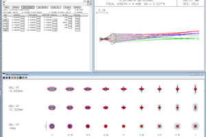
 helge
helge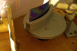
 andreas.betz
 David H Haffner Sr
Thank you so much for sharing your work! It has been extremely helpful. Can I ask, how did you select the dimensions of the input slit?