Close
0%
0%

Refreshable Braille Display

A cost effective way to make a refreshable braille display

Similar projects worth following
Of 40 million blind people in the world, only 10% can read and write braille.
One of the primary reason for this is because braille hasn't yet found its footing in the digital era, due to the sheer cost of such devices, as well as the affordability matrix of the visually impaired.

Low-cost braille displays have been sought after for quite a while with no avail.
Commercially available braille displays employ peizo-electric actuated pins, which are very expensive.

Due to the sheer expense of braille technology, and the scarce availability of books in braille, the medium is slowly falling out of favour. But many agree that braille literacy is paramount for the empowerment of the blind for education and employment.

The display would be used along with https://hackaday.io/project/10745-brailler-style-keyboard to make a full modular braille computer

I have been working with braille for about 3 years now. My first attempt at a prototype used a dot-matrix printer head: http://www.angadmakes.com/my-portfolio/virtual-brailler

At Makerfaire Bangalore, I met Paul D'souza and was amazed by his innovative designs for refreshable braille displays. One of his designs used these vibrator motors.

Im looking to build on that brillant idea and build a system that is more robust and can be understood and reproduced and improved by people all over the world for the visually impared , similar to how the open source prosthetics movement have helped so many amputees.

The method of working is as follows:

Motor+Cam :
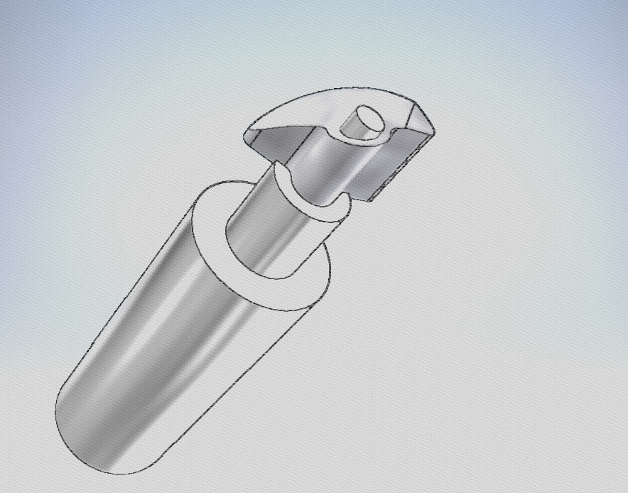

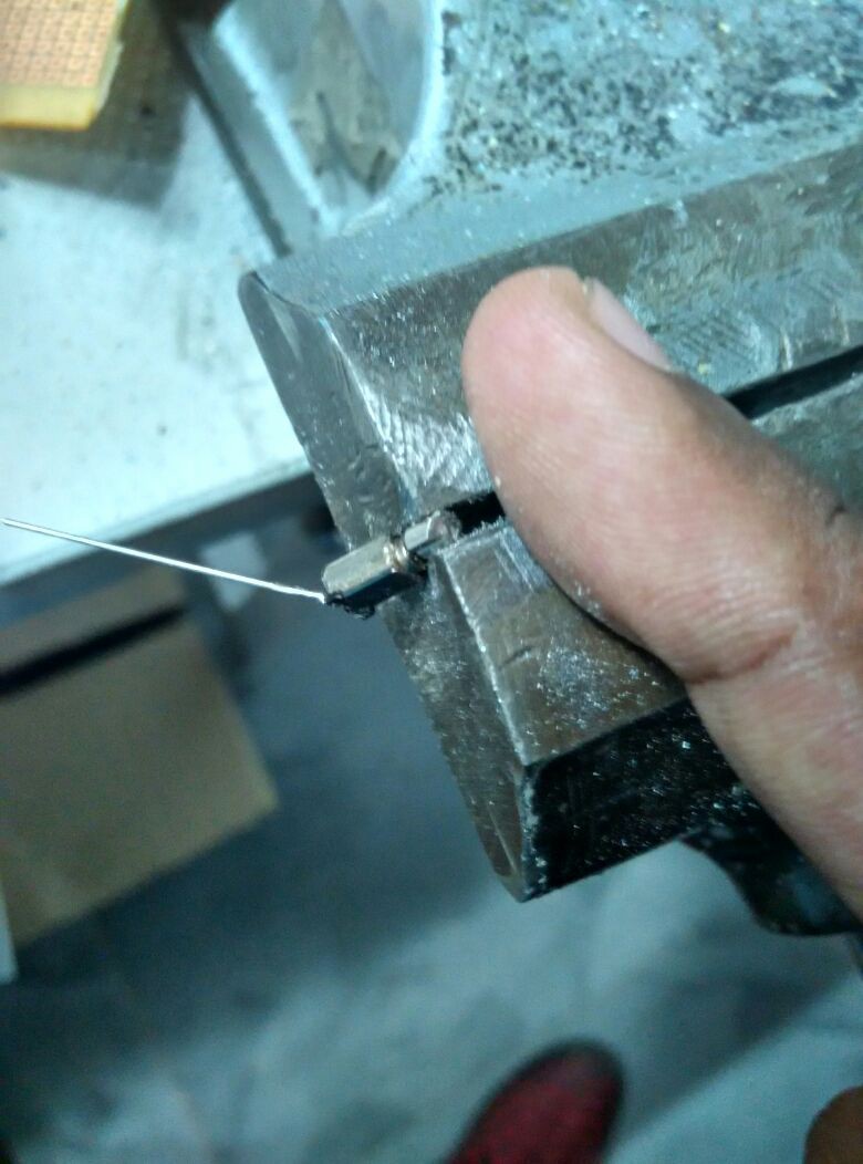
The heart of the mechanism is a series of pico-motors that are commonly used as vibration motors with a weight on the end.

We modify the weight to have a profile similar to the above so that is may act like a cam, when shaft axis is verticle.

Motor holder + Stoppers:
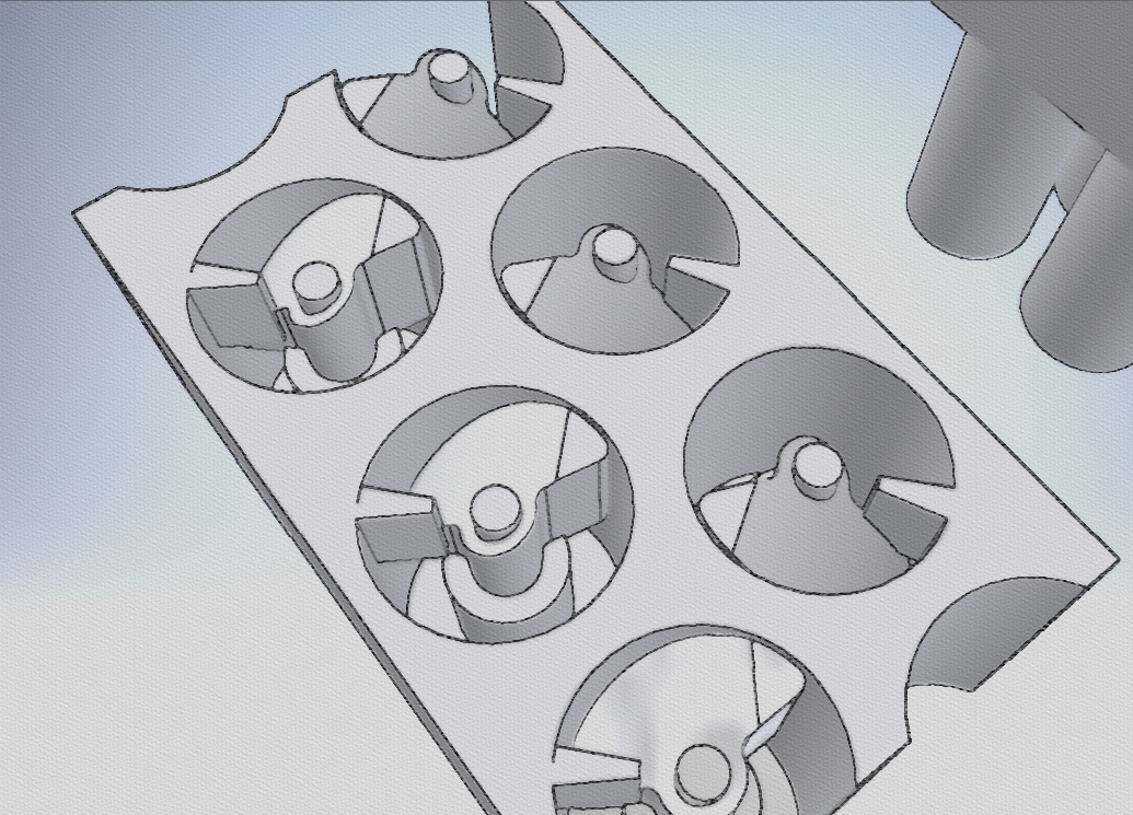
The motor holder holds all the motors in the appropriate positions to actuate the pins. There are stoppers that prevent the cam from rotating continuously that are integrated into the design.

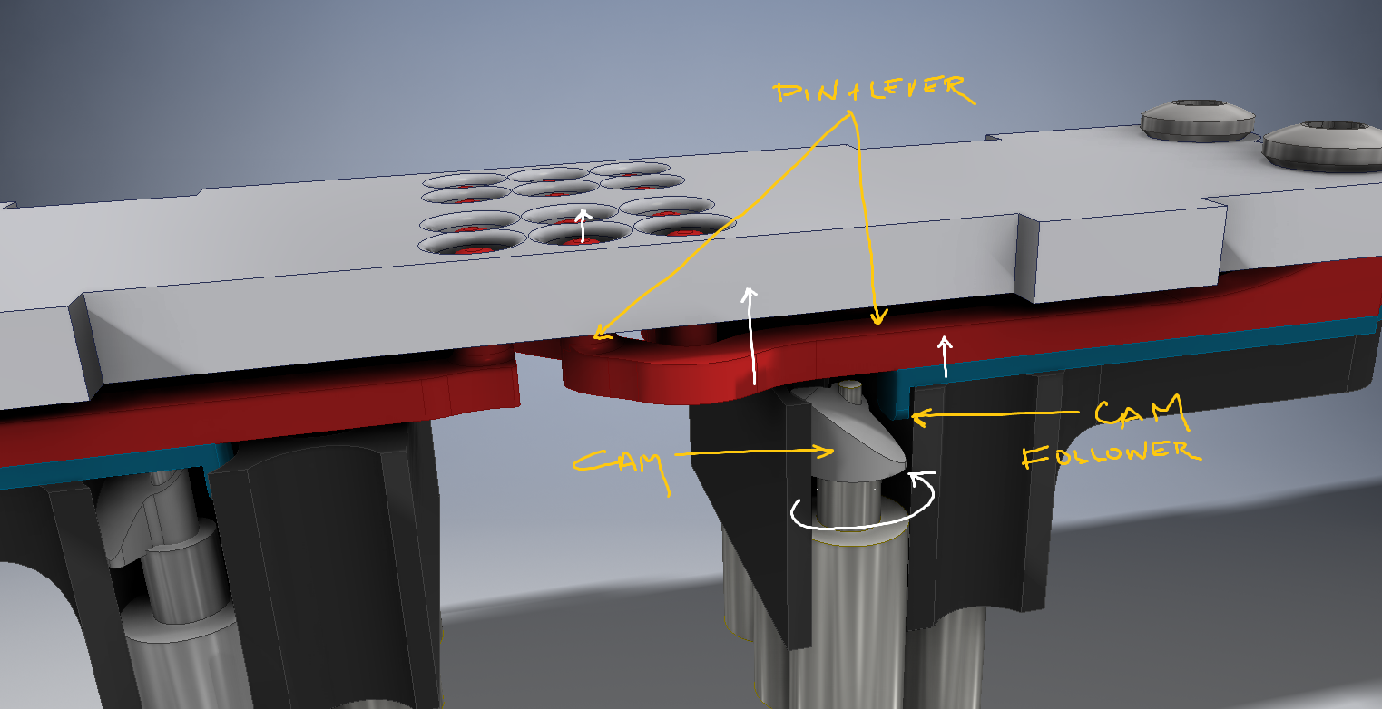
At the particular position where the cam followers are placed, depending on the rotation of the motor, the cam follower will he higher, when motor rotates one direction, and is lower in the other. The stopper make the motors behave in a "binary" fashion. The functioning will become clearer once the cam follower is explained.

Cam follower + Lever + Spring + Pins:
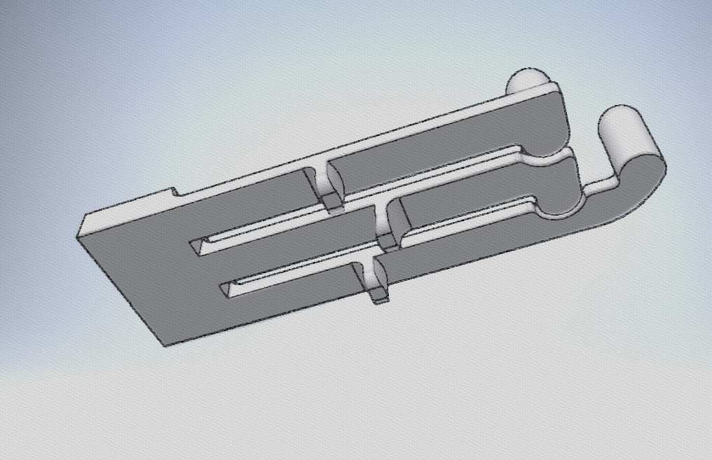

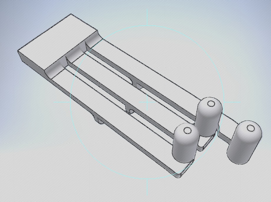
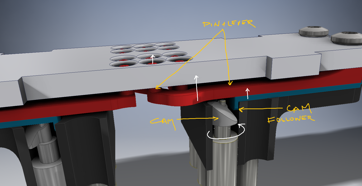
The cam followers, that will be riding on the motor's cam is shown in the first image( the three projections). The cam follower is attached to the lever bar, that is fixed on one end ( the large rectangular part). The level bar has the braille pins on the other end.

The material used for this part would be ABS, or Nylon, that would be slightly flexible without causing fatigue.

Thus the movement of the cam, wold cause the cam follower to move up, that flexes the lever pushing the braille pin upwards and the lever is displaced from its natural position. when the cam causes the cam follower to fall, the level bar falls back to its natural position and thus acts like a spring.
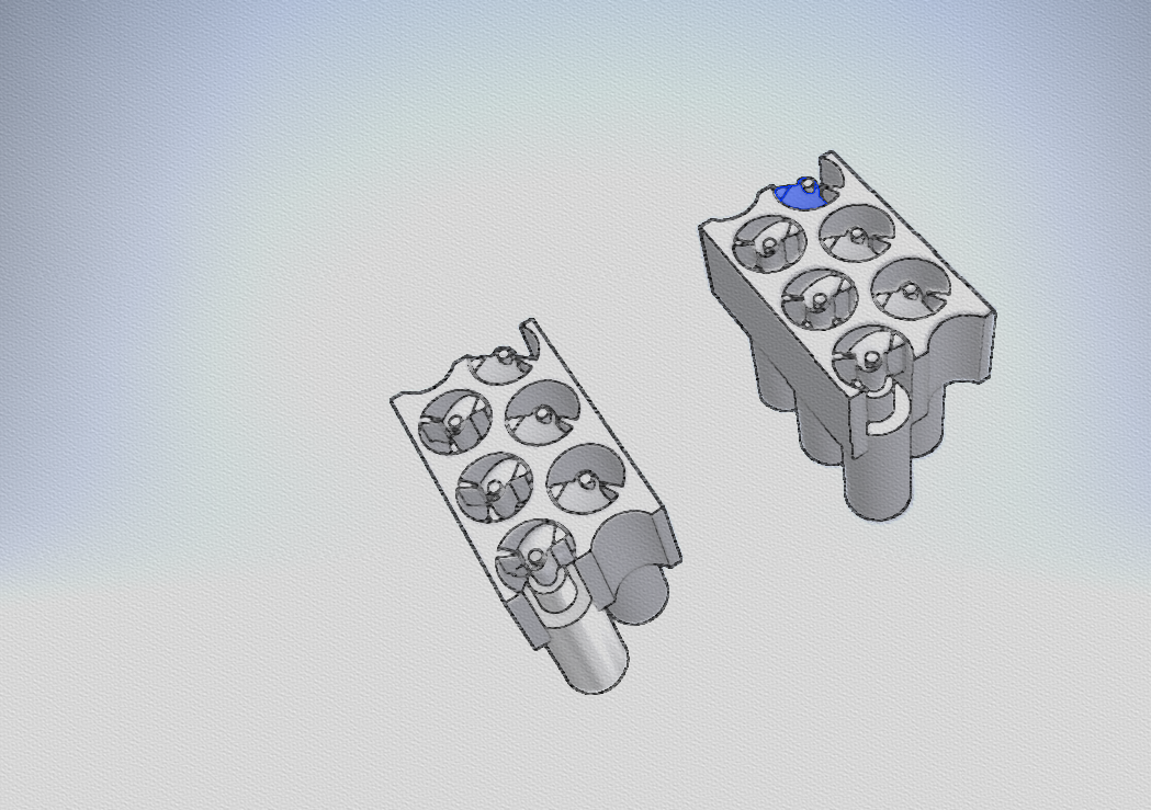
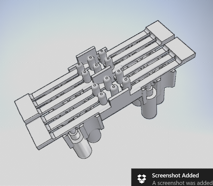
Everything is assembled in the above fashion. Two lever arrangements and six motors make up a single braille cell.
Faceplate+ Pin Guide:
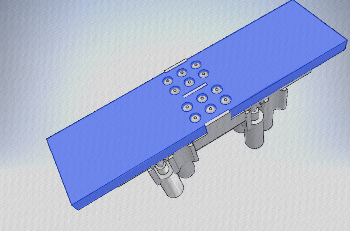
The faceplate forms the surface on which the pins pop out.

One module contains two refreshable braille cells( like above).Modules will be linked together to make a full braille display. i.e, for a 20 character refreshable braille display, 10 modules would be used.

The below image illustrates the working better. the white arrows indicate direction of motion.
cern_ohl_v_1_2_howto.pdf

Cern Open hardware Licence 1.2

Adobe Portable Document Format - 55.06 kB - 04/19/2016 at 18:53

Preview
Download

cern_ohl_v_1_2.pdf

Cern Open hardware Licence 1.2

Adobe Portable Document Format - 95.73 kB - 04/19/2016 at 18:53

Preview
Download

  • Motor-gasm : The most amazing motor on earth!

    Vijay07/12/2016 at 20:20 9 comments

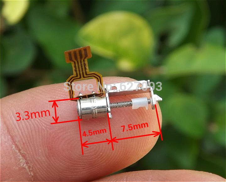
    The micro stepper motors I ordered just arrived, and god are they brilliant!

    I did some rudimentary experiments about the amount of torque it has, and if it would suffice for my application, and I think it would, although i'm afraid it might miss steps.


    I'm driving this straight out from the Arduino pins that should be ~40mA source and sink. Possibly some more juice from a proper driver will do the torque some good.

    Let me know what you think. I would also like to thank all those who responded to my earlier log, especially @HTCPCP 418, whose micro stepper motor driver approach, ill probably be taking.

    Ill be uploading CAD data for these motors in a few days if anyone is interested.

    The link to this motor is : http://www.aliexpress.com/item/50pcs-2-Phase-4-Wire-Micro-15-Step-Motor-Screw-Rod-Stepper-Stepping-Motor-Free-shipping/32222560547.html?spm=2114.13010608.0.78.tjruAc


  • Help needed driving multiple stepper motors.

    Vijay06/26/2016 at 07:02 16 comments

    We are trying to figure out the best way to drive as many stepper motors simultaneously ( for the actuation system mentioned in the last post ) .

    -There are 40 stepper motors in total for a 20 cell braille display, two per each cell. They preferably need to be actuated simultaneously.

    -The motors do not require too much current ( unknown amount since there is no datasheet, motors will arrive in a couple of days)

    -The motors are 4 wire- Bipolar steppers, with 15 step a rotation.

    -it takes roughly 25 rotations of the stepper motor to reach from one end of the linear selector system to another.

    Some of the approaches friends have suggested:

    -Using many stepper drivers like allegro or TI's solution each connected to a slave MCU like an attiny85, that takes serial input. ( i.e, each braille cell has stepper motor controller and a MCU)

    -Using a I2C, SPI port expander connected to a main MCU

    -Using an LED driver

    Any suggestions for this problem?

  • ! New Actuation System !

    Vijay06/22/2016 at 20:42 3 comments

    I've been straight at it, thinking about alternatives for the last actuation system after last weeks events. I think ive got a good robust system this time, that actually is simpler than the last one in terms of components and size. Lesser parts to be 3D Printed, and more that can be bought off-the-shelf

    Using

    Micro Stepper Motor

    +

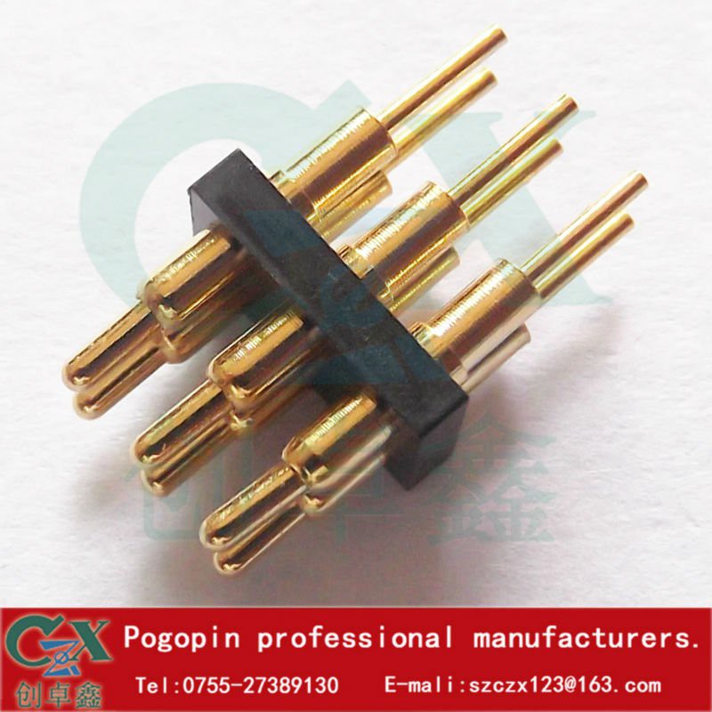
    3x2 Pogo pins

    =

    Using retractable pogo pins, that are engaged/disengaged using some sort of linear motion ( servo/ stepper/spring/solenoid for up and down motion) that pass though a pin-selector slider mechanism that allows only some select pins to pass actuated by the micro stepper motor.

    note: once an array of these is built, the engaging/disengageing ( up and down) motion of the pogo pins can happen simultaneously( for all braille cells together) with a since actuator.


    What do you think?


  • Discontinuing work on current actuation method

    Vijay06/18/2016 at 20:51 3 comments

    Hi all,

    As mentioned in my previous post, it’s been brought to our attention that features of the open source refreshable Braille display project have already been covered under a patent application filed by Paul D’souza on 5th November, 2014.

    Paul’s patent describes the use of “micro-motor actuated pins, the pin cantilever design, the mechanical stop to limit rotor rotation, motors with rotors or cams, mounted vertically or horizontally used to lift pins directly or via an interposer, low force selector etc” - many of these are featured we have included in this device.

    Paul has requested we discontinue the project in the interest of potential manufacturers and licensees of his patent, as well as to avoid any legal obligations he may face with the patent office. As a result, the CERN Open Hardware License the project was released under has effectively been invalidated and so I have discontinued work on this current method of braille pin actuation. The patent will severely restrict any global (and particularly local) impact we can make with this project, which was our whole motivation.

    However, I would like to make clear that the designs and documentation we have released have been created from scratch, sharing only the working principles of Paul’s patent. My intention has always been to make a completely 3D printable refreshable braille display that anyone can access and I have been working on braille technologies for the past three years. As part of this work, I have developed software to convert text documents to braille and built two refreshable braille display prototypes, one using micro servo actuators and another using a hacked dot-matrix printer head. At that time, I was still a kid in college and didn’t have much knowledge about production techniques or skill in design, CAD, and electronics.

    Things have changed a lot since then. Going through the process of setting up and running a 3D printing and product design startup, I’ve learned exactly what I need to know to create just about anything. I actually met Paul at a local Maker Faire and we instantly connected because of our shared efforts on braille and I was amazed and intrigued by his genius ideas for actuation. This meeting resparked my passion for braille and I began using cell-phone vibration motors as a method of actuation along with my experience with FDM 3D printing and product development to create a solution that anyone in the world could potentially have access to just by downloading the files.

    What’s more, I was lucky enough to have the opportunity to show one of my early braille display prototypes to the president of India, Dr. APJ Abdul Kalam, before he passed away. He made me promise that I would do everything in my power to ensure the project would reach the people that it matters most to and that has become my life's mission ever since.

    Since the 3D designs and documentation are my own original intellectual property, I will be releasing everything under Creative Commons Attribution-shareAlike 4.0 International. This is an open source license that allows anyone to use, modify, and share the documentation and 3D designs under the same license. However, anyone wishing to manufacture and distribute the device itself should contact Paul D’Souza on pgdsouza@gmail.com. I have done this to ensure that people can make a personal copy for studying purposes.

    I will certainly not stop working on the refreshable braille display due to this hiccup. I have seen some amazing motors from Aliexpress while buying motors for the current system and I am confident that by collaborating with other members of the open hardware community we come up with a “patent infringement free” solution that is feasible, scalable, and will achieve my goal of bringing digital literacy to the visually impaired all around the world.

    I wish @PAUL DSOUZA all the best, he has been incredibly supportive on this project, and multiple others my team and I have been working on. I...

    Read more »

  • Updates!

    Vijay06/17/2016 at 15:26 1 comment

    On suggestion from @Yann Guidon / YGDES I've scaled the mechanism by 1.1 times. It changes the dimensions by a very small amount (0.6mm over a character) so that I can accommodate 4mm motors for the time being since the 3mm ones are proving hard to find. I shall maintain another copy of this version of the mechanism in another folder.

    Using the prize money from the "Anything Goes" round ( YEY!) ive purchased the following motors and eagerly await their arrival:

    http://www.aliexpress.com/item/5Pcs-DC2-3V-1500RPM-4mm-Dia-Coreless-Vibrating-Motor-for-Mobile-Phone/32637931060.html

    The electronics design will take advantage of the spring leads of the motors to have a "solder-less" connection to the driver board. As mentioned in an earlier post, it driver circuitry will be similar to that used in Flip-Dot displays (Thanks Martin )


    I have been requested by @PAUL DSOUZA to make everyone aware that the features mentioned in this Project thus far are covered under a patent application filed at The PatentOffice, Chennai, by him on 05Nov2014 …5559/CHE/2014. If anyone wants to exploit features of this design, they would need to get in touch with Paul or his patent attorneys (Origiin IP Solutions LLP), as rules require that even the Patent Office to be kept informed of activities in regards to patents.

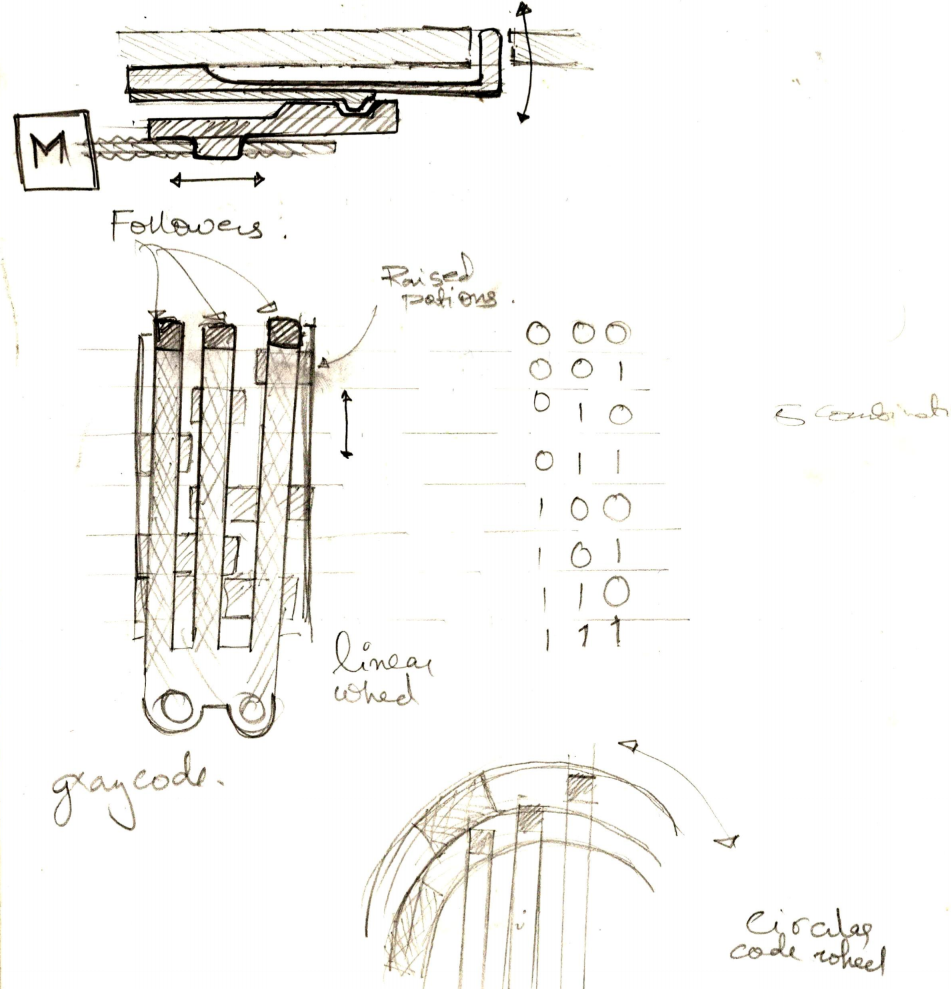
    I have also been toying with the idea suggested by @Keith Minsel using cams to drive the pins. After finding some really cool motors on aliexpress (God bless China) Ive made up my mind to make a prototype using a stepper-cam system to lift pins up and down.

    I'm considering using either a linear compound cam, on a circular one. I hope people can decipher the drawings above, The prongs are the same cam followers that I have currently on the design, only the motor block would be replaced. Any help with making the decision is appreciated( circular or linear)


    The stepper motors: http://www.aliexpress.com/item/hot-salow-price-20pcs-extra-Micro-stepper-motor-DC-Stepping-motor-with-Screw-Dia-3-3mm/2053510670.html?spm=2114.10010108.100009.4.UGX6T0

    I guarantee the size would surprise you.

  • Thats one tiny motor!

    Vijay05/12/2016 at 17:30 0 comments

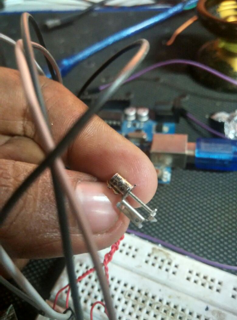
    I found a single 4mm dia motor from somewhere, and am in the process of modifying to see if it works. it struck me how small these things are!

    I'm also in the process of working out the electronics, looking at how Flip Dot displays are run, and probably follow the same method for the driving circuitry.

    Using the following resources for that ( Thanks to Martin for the idea) :
    http://www.dhenshaw.com/Art/Dottie/start.htm

    https://wiki.attraktor.org/FlipdotDisplay


  • Pin actuation looks promising!

    Vijay04/29/2016 at 12:06 2 comments

    I couldn't get the motors I need, but was able to source a 6mm dia version (double the size I need) to see if the cam+follower thing would work, I just couldn't take the suspense of not knowing!

    I was too lazy to CAD anything for the test, I had to know IMMEDIATELY!

    so I ground the weight to a shape I wanted, got my friends iPhone to record in slow mo, and it looks promising!
    I can't be 100% sure the final would work, since the actual motors I need to use are smaller, but I feel it's got a fighting chance!

    I also realised I'm using 2 simple machines, a lever and a ramp, and it oddly satisfies me for some reason.

    Inferences:
    - there is only a ~0.5mm lift required at the cam follower to achieve the required lift at the pin.
    Hence, a shallower angle on the cam, would make it even more easier to lift the pin ( because of the shallower slope of the ramp of the cam )


    I contacted sales at Precision Microdrives about sponsoring their motor, https://pmdri.zendesk.com/attachments/token/koNuCT5zcZuO6kQC6E56rh040/?name=303-103-datasheet.pdf

    They got back saying they won't lower the MOQ or the price :( gotta figure out another way of getting my hands on them, or else try and change the design to use 4mm dia motors from china ( highly unlikely they will fit the requirement due to the size constraint)


    A big thanks to @Anool Mahidharia for the article on Hackaday today!
    http://hackaday.com/2016/04/28/refreshable-braille-display-and-braille-keyboard/


  • CAD design changes and improvements

    Vijay04/27/2016 at 21:22 0 comments

    Updated the description with the above image. As you can see, the changes in the last few logs now reflect the CAD design.

    -The Cam Follower(blue) & Pin Lever(red) are different parts to aid 3D Printability

    -Jig-saw type thingies on the sides, for chaining the module to create a full display

  • Cam followers+ Spring action working!

    Vijay04/24/2016 at 15:45 0 comments

    The cam followers were printed, and came out beautifully . The Spring action works just like planned.

    the only thing left to test is the cam actuation with the motor.

    Link and description of the motor :

    https://www.precisionmicrodrives.com/vibration-motor/3mm-vibration-motor-8mm-type

    The MOQ and price is a little expensive for me at the moment, I will be contacting them and asking if they will sponsor the motors for the project.

    The video below shows the cam followers and the spring action pulling the pins back down after pushing the cam followers up.

  • The perfect tolerances: Assembly time!

    Vijay04/19/2016 at 18:32 0 comments

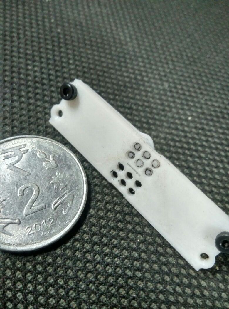
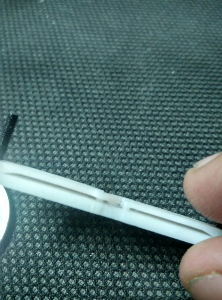
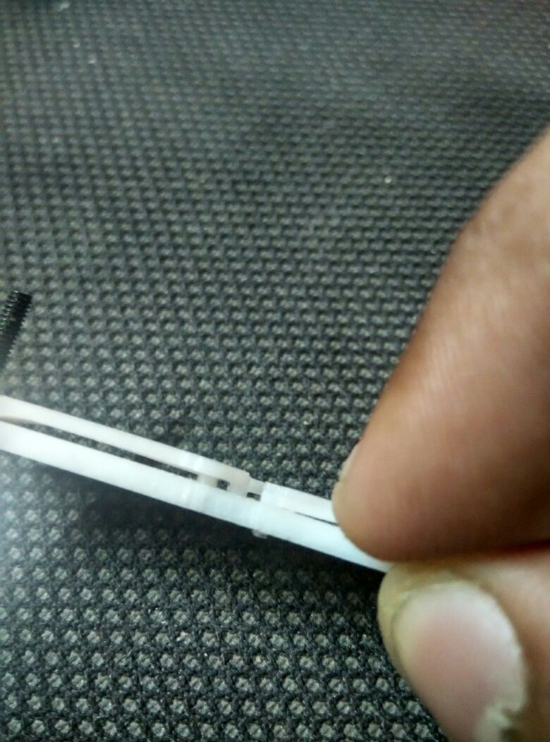
    The above image shows the shaft-lever part into the braille cell plate. It took 4-5 iterations (available on the dropbox link) to get the tolerances just right, such that the pins don't get stuck in the shaft of the braille cell plate.

    The above image shows the side view of the braille cell's, along with the pin-lever part assembled and held in place with an M2 screw. the pins are "below" the surface of the braille cell plate when not pressed, due to the spring action of the lever ( by the cam follower)

    In the above image, I'm applying a slight force on one of the lever, that causes the pin to move up. Quite simple really.

    Now its time to test with motors!

View all 13 project logs

View all instructions

Enjoy this project?

Share

Discussions

Karl-Wilhelm Wacker wrote 04/26/2016 at 22:13 point

Looking at the pin arrangement and the suggestion of using coils and magnetized pins made me think of another technology:  core memory.  Instead of a coil for each pin, wind rectangular coils so that you have three coils going across the [4] pins of two letters, and four coils, one for each  column of [3] pins.  drive an x-y pair of coils at the same time in the same 'direction, and only one pin would have the combined magnetic field to move up or down.  this lets you use 7 push-pull drivers  for the coils instead of 12.

  Are you sure? yes | no

Vijay wrote 04/27/2016 at 10:01 point

I've been learning so much from people on hack a day, thankyou! I didn't know of core-memory until today! (https://en.wikipedia.org/wiki/Magnetic-core_memory)

This got me thinking of the electro-permanent magnets being used in google's project ara phone.  Electric potential will only we required to change the state.

  Are you sure? yes | no

K.C. Lee wrote 04/27/2016 at 12:00 point

I am thinking something like power inductors.  e.g.  http://www.coilcraft.com/me3220.cfm

3.2mm diameter.  Use these tiny disc shaped rare earth magnets from China. 

e.g. http://www.banggood.com/search/magnets.html

The inductor is on a ferrite core, so there will be some attractive force.  You can reduce the force a bit by having some minimum separation between the magnet and the coil.  You'll only need to apply current in one direction to repel it. 

Only issue is how much current and if the current is within Irms rating for heating.  If the current is small enough, there are SPI low side drivers with onchip protection etc.  Just have to google for "spi low side peripheral driver chip"

  Are you sure? yes | no

Vijay wrote 04/27/2016 at 18:22 point

You sir, are a genius! Using off the shelf power inductors is a brilliant idea, and keep the cost low, and makes assembly/reproducibility easy.

 I've been thinking how to wind the coils myself. I shall give this a try and let you know how it goes!

  Are you sure? yes | no

Vijay wrote 04/27/2016 at 19:18 point

I did a quick attempt at trying this, I got a ~3-4mm diameter indutor+core and a 10mm dia rare earth magnet. used 5V at ~ 1 A to power the eliminator. 

The attraction between the magnet and the ferrite core was more than the repulsion caused by the turning on of the coil. 

Maybe one with a smaller core would work better? you think its a good idea to keep persuing this and try a few more times?


  Are you sure? yes | no

K.C. Lee wrote 04/27/2016 at 21:20 point

I don't know the right answer to this.  The only thing I suggested is to have a minimum separation distance - put a cardboard shim between the inductor and magnet to weaken the force a bit.  There are also air core inductors for RF, but they are not designed for high currents.  Beyond that, it might need a lot more turns of coils than such types of cores.

In the old dot matrix printer, they have solenoids spread around the pin head and use pieces of steel wire to redirect the force.  The wires also do the printing.  It is a hell of a mess to fix the head - I keep mine alive by fixing it every few months for a while until I gave up.

  Are you sure? yes | no

Yann Guidon / YGDES wrote 04/28/2016 at 00:44 point

"You sir, are a genius!" He always surprises me so that must be why :-)

K.C.'s electromagnetic core proposal sounds very interesting to me.

The modified cam is a nice trick but it does not fully exploit the electromechanical properties of the tiny motor. These 3mm or 4mm motors are designed for high speed, not torque, so they will heat a lot with pretty small torque, and I suppose they would need mechanical amplification with gears (micro-planetaries ?)

OTOH Lee's proposal reuses existing power coils (cheap !) with a very well understood and simple electromagnetic circuit. It's easy to control 1A currents (or more), the voltage does not need to be high so the actual power is a few Watts during a fraction of second.

What is also missing frmo the overall design, IMHO, is position sensors. A couple of wires should indicate that the moving part has reached one end or the other, so the driving current can stop, and a safety mechanism is triggered if it stays "inbetween" after a reasonable time (indicating electric or mechanical fault). Or even if the current is too high.

Good luck, I have doubt about the micromotors with simple cams, but I hope you will prove me wrong or find a better system.

  Are you sure? yes | no

Vijay wrote 04/29/2016 at 08:25 point

@K.C. Lee I know what you are talking about, with the dot matrix head. My first prototype when I started attempting refreshable braille used it. 

It would heat up too much, and would scare the blind when I tried user testing, because of the heat of sound.

I'll keep trying with different inductors, lets see what works.


  Are you sure? yes | no

Vijay wrote 04/29/2016 at 14:55 point

@Yann Guidon / YGDES The position sensor is a good idea and will be needed thanks!

Check out the latest log, the cam thingy look like it might work, I was skeptical myself!

  Are you sure? yes | no

surubarescu wrote 04/26/2016 at 14:37 point

You can use the motors from old phones. You can find them at a phone repair shop or at companies that recycle electronics. 

  Are you sure? yes | no

Vijay wrote 04/26/2016 at 17:30 point

Thanks!

most of the motors I've seen so far have 4mm diameter body. The company mentioned above is the only one who makes 3mm that I am aware of. 

According to the design, I can push for a maximum of 3.5mm diameter motor body.


If you have seen smaller ones let me know!   :)

  Are you sure? yes | no

surubarescu wrote 04/27/2016 at 09:45 point

All the phones i had opened were Nokia and they seem to share the same motor or at least same form factor motor.

  Are you sure? yes | no

Jan wrote 04/26/2016 at 10:09 point

Unfortunately I can just give you one skull. Amazing project!

  Are you sure? yes | no

Vijay wrote 04/26/2016 at 17:30 point

Thank you so much!

  Are you sure? yes | no

Audrey Robinel wrote 04/26/2016 at 01:01 point

Hi there, this is truly a great project. Not only the concept, but also the engineering behind it. Good luck for next rounds :)

  Are you sure? yes | no

Vijay wrote 04/26/2016 at 08:02 point

Thank you so much! :D

  Are you sure? yes | no

johnsamisoni wrote 04/25/2016 at 23:34 point

My project I was thinking was gonna use a refreshable Braille display but mine were gonna use electromagnets do you think I could use a similar idea to yours tweak here and there? 

  Are you sure? yes | no

Vijay wrote 04/26/2016 at 08:03 point

Sure! thats the idea, to open source everything so that anyone can take it up, use it and make it better! keep me posted!

  Are you sure? yes | no

Martin wrote 04/25/2016 at 12:20 point

Why not using a bistable remanence-magnetic approach like flip dots? 

The pin would be made out of steel of medium high B_r. In the backside is a permanent magnetic plate and around each pin is a solenoid coil. A positive current pulse magnetizes the pin in such a way, that it is repelled from the back plate and sticks out, a negative current pulse magnetizes the pin the other way round, it retracts and sticks to the magnet in the back

  Are you sure? yes | no

Vijay wrote 04/25/2016 at 13:45 point

 I just learnt something new: flip dot displays! thanks!

Do you think it would fit in the size required? the diameter of the pin + coil is what I'm worried about, and whether is can take the weight of a finger going over it, without being depressed to easily( so that one can feel the pin)

Worth a try though, the wire would need to be absurdly thin, and maximise the number of coils wihout falling out of the braille size specifications. 

  Are you sure? yes | no

Martin wrote 04/25/2016 at 14:57 point

There is magnet wire at least down to 0,06mm. You have to be careful, it is quite fragile but hand winding is manageable. Somehow they have to wind this tiny vibrator motors.

Of course the position where it sticks to the magnet has more force than the other one. It would be nice to make this the stick out position. But for this you need a permanent magnet with a small hole for the then non magnetic (!) pin and a thicker magnetizable core. Or perhaps an off center solution is possible

  Are you sure? yes | no

Vijay wrote 04/26/2016 at 17:32 point

I was thinking this over today, if  I can modify the "cam follower" part of the design to use electromagnets, it may just be possible to fit it all in, at the same time make use of the mechanical advantage of the lever!

  Are you sure? yes | no

Gabriel wrote 04/14/2016 at 21:38 point

Wow... its tiny!

your design makes total sense now.... good work man!

  Are you sure? yes | no

Michael wrote 04/13/2016 at 20:14 point

This is such a great idea, especially using the vibration motors & modding the weight to make a cam!

  Are you sure? yes | no

Vijay wrote 04/14/2016 at 17:14 point

Thanks! I just hope they have enough torque for that. 

  Are you sure? yes | no

Gabriel wrote 04/12/2016 at 17:21 point

I see what you did there.

Awesome project, however have u considered using the cam to lift the touch pin directly?

it already has weight (read finger) on it so no spring other spring action is needed, or have the pin magnetized so it sticks to the cam and retracts.

this would reduce size considerably, maybe even allow for more characters to be grouped.

Im not blind but i assume they are pretty touch sensitive so not much lift would be needed.

  Are you sure? yes | no

Vijay wrote 04/12/2016 at 18:27 point

Hi!

well, the standard maximum space an entire braille character can take is about 6mm 

One motors diameter is 3.2mm, its the smallest I could find online. Ideally, yes lifting the pins directly would be great, but there is simply too little space to play around with. The arrangement proposed alows for the motors to take more room, plus you have the mechanical advantage of the lever. 

I'm trying to follow the braille spec as much as possible.

The pin being magnetised is a good idea! I'm worried if the pins would get stuck in the bore, since the movement is a slight curve and not absolutely perpendicular, having it magnetised and following the cam exactly might help.


  Are you sure? yes | no

Gabriel wrote 04/13/2016 at 02:02 point

Huh... i didnt think it would be that small!

  Are you sure? yes | no

Gabriel wrote 04/23/2016 at 15:05 point

This is looking Fantastic man.... awesome, awesome!

I wish i could skull again.

You are going places with this, for sure!

  Are you sure? yes | no

Vijay wrote 04/25/2016 at 13:46 point

Thankyou! :D

  Are you sure? yes | no

SYED JUNAID AHMED wrote 04/10/2016 at 15:14 point

awesome :)

  Are you sure? yes | no

Similar Projects

Does this project spark your interest?

Become a member to follow this project and never miss any updates