 AndrewMcDan
2018 Update
After much time and little progress, I am getting back into this project. So here's the long short-version:
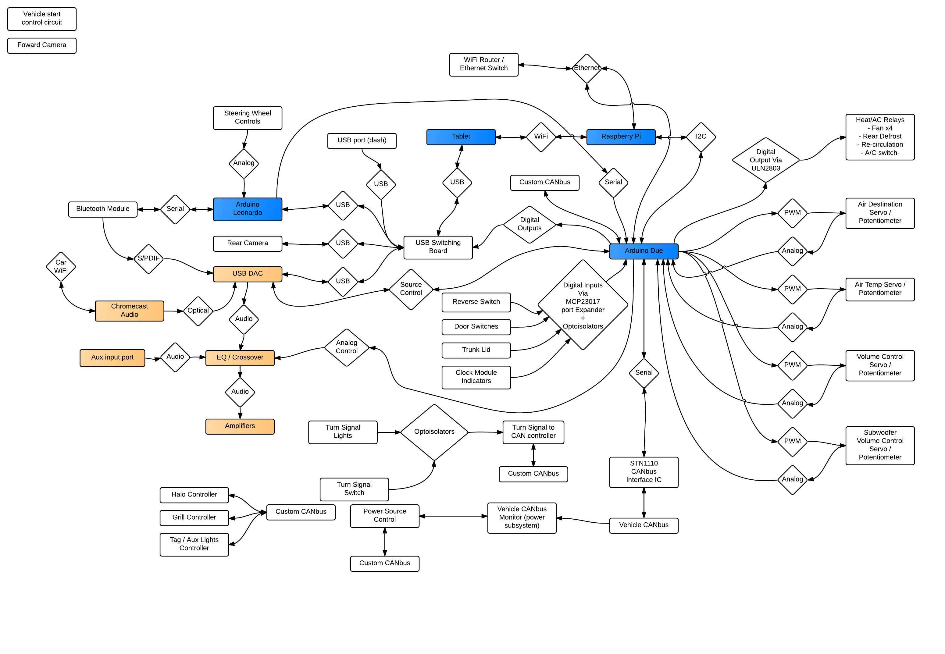
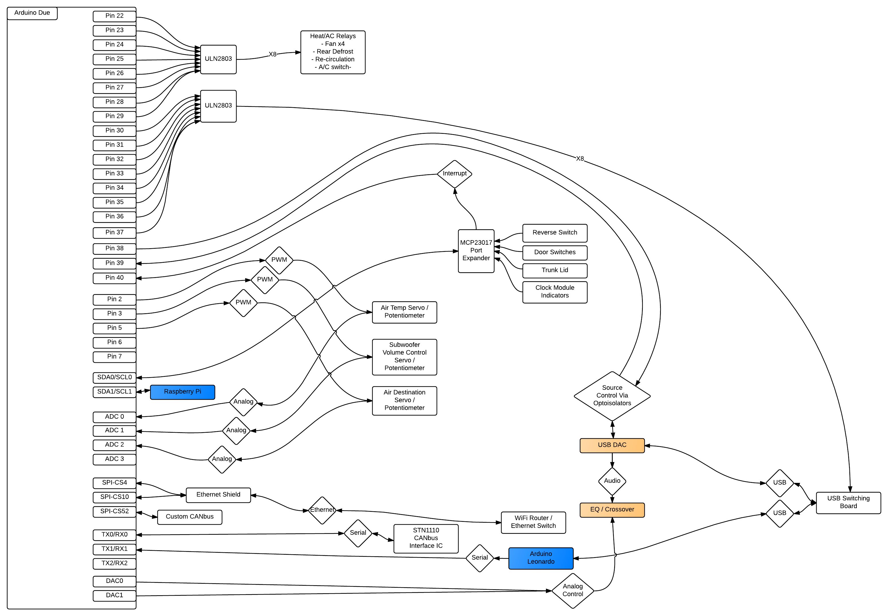
The plan is to install a touchscreen LCD in my dash in place of the stereo and climate controls. This LCD will be the interface to a Raspberry Pi that will be the primary brain of this project. Connected to the RasPi via various methods will be controllers for performing various tasks (volume control, lighting control, climate control, audio source control). If you follow this project, please be aware that I may not update it very often. ...sorry.
| OLD STUFF |
| | | |
\/ \/
I am currently working on a very detailed document describing every aspect of this project. It can be found at this link: Description on Google Docs. It is a work-in-progress and should reflect the most recent design. I will keep that link as up to date as possible, but this project page will not be updated as often as the G-Docs file. This project page will also not have the level of detail that the G-docs file contains.
I've changed my mind on the overall design for this project several times. Currently, the plan is to mount my Android tablet into the dash of my car and use it as my source for music and the primary interface for the other systems I'm installing / modifying in the car (lights, AC/heat controls, etc). The tablet will be connected to a USB DAC which will feed into a line level pre-amp, then on to the power amps. The tablet will also be the screen for my backup camera.
I'll be working on this project in stages but can only start installing pieces once all the main parts are done. This includes mounting the tablet in the dash, completing the software to run on the RasPi, completing the auxiliary battery and power supply, installing the audio hardware (including building the electrical interface for the steering wheel controls), and building the mechanical and electrical interfaces for the heat/AC controls. In the process of building all of these parts I have to take into consideration and plan the other things I plan on incorporating into this build, including the turn signal system rebuild, auxiliary lighting, and dash camera / DVR.
Background
When I purchased my new phone (Galaxy Note 3, if you're curious), AT&T gave me a tablet for free (as long as I signed up for a two-year contract for the tablet). At that moment I had the great idea of installing this tablet in my 2012 Scion tC so I accepted their terms. Since then, I've been working on this project but haven't made much headway as far as installation goes. I've mostly been trying to work out the logistics of the project and have been tossing around several ideas for how to go about implementing my idea. At this point, I've been at it for about a year. The overall project design has gone through several iterations and I have finally arrived a a version that meets all of my requirements. Instead of mounting the tablet in the dash as the direct interface, I'm going to replace my stereo with a headunit that has HDMI / MHL capability. Using that feature, I'll route video from my old Galaxy S3 to the headunit and use the headunit itself as the primary interface. Because I'll be able to use the headunit screen as the interface to the phone, I'll be able to access all the features of the phone. I'll use the SIM card from the tablet to enable data-only access to the cellular network, and I'll still use the tablet to control accessories and view data about the vehicle.
Initial design ideas
When I first started working on this project, I had no idea how I was going to make it work. And so I started off with simply trying to decided where in the car I wanted to install the tablet. My first instinct was to install it where the stereo is but I didn't want to lose the option of playing a CD or listening to broadcast radio. And so I started to consider other places in the dash to install it....
Read more »


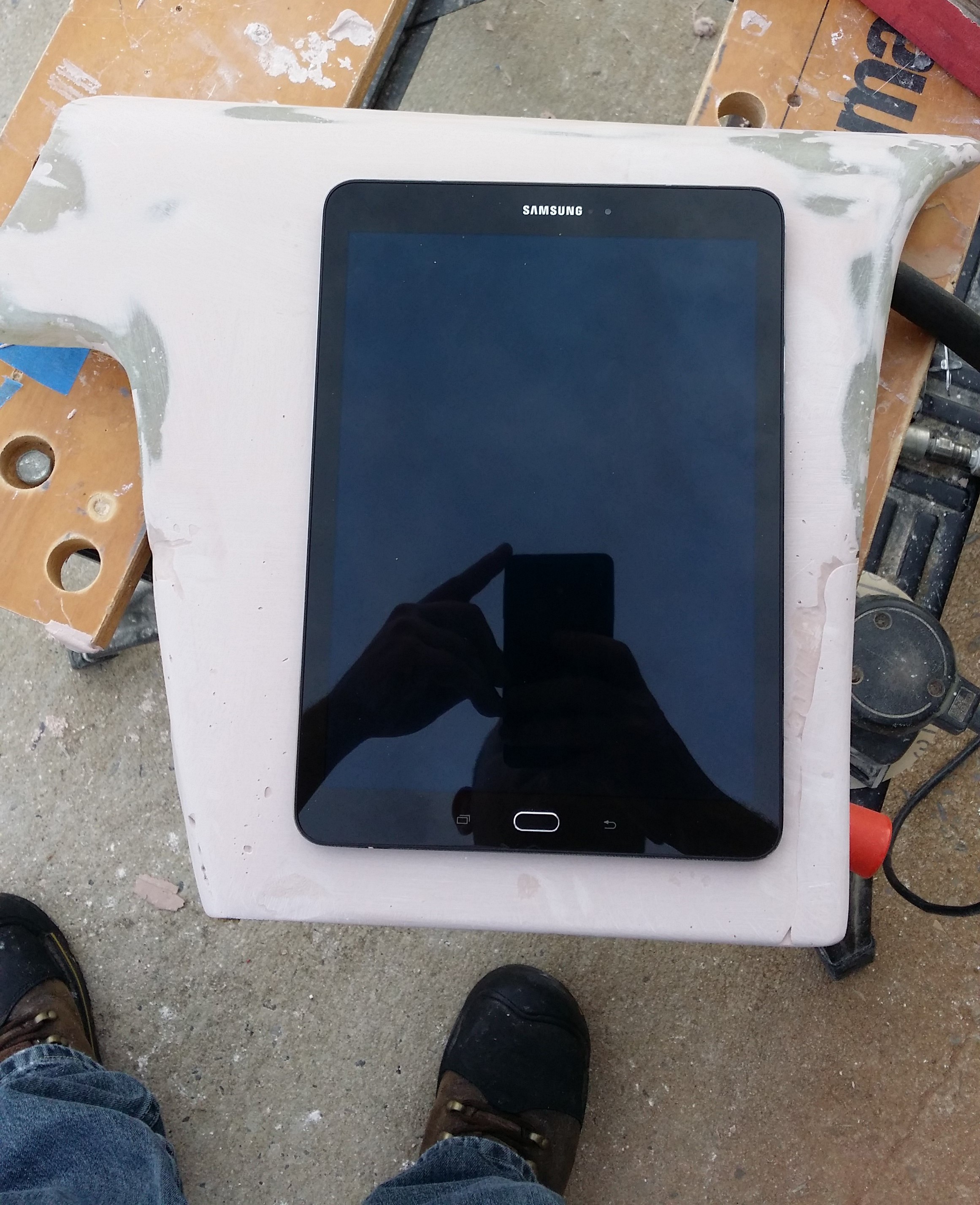
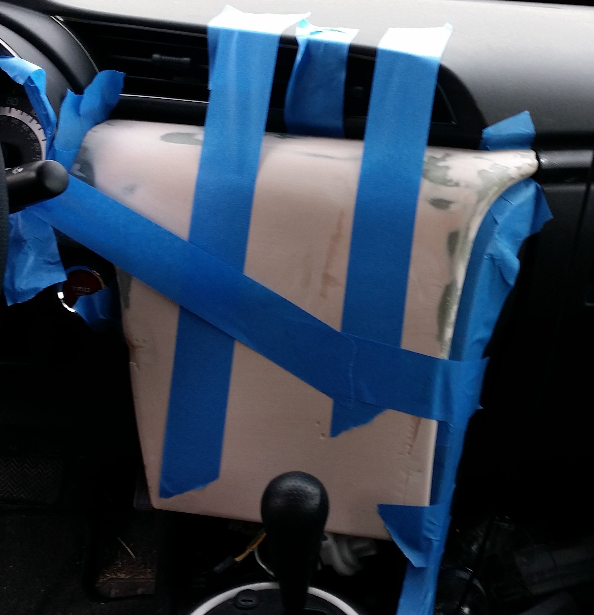 The new dash panel is coming along nicely. The first picture shows an approximation of where the tablet will be mounted in the final piece. The second is a mock-up of the piece in the dash. That's all for now.
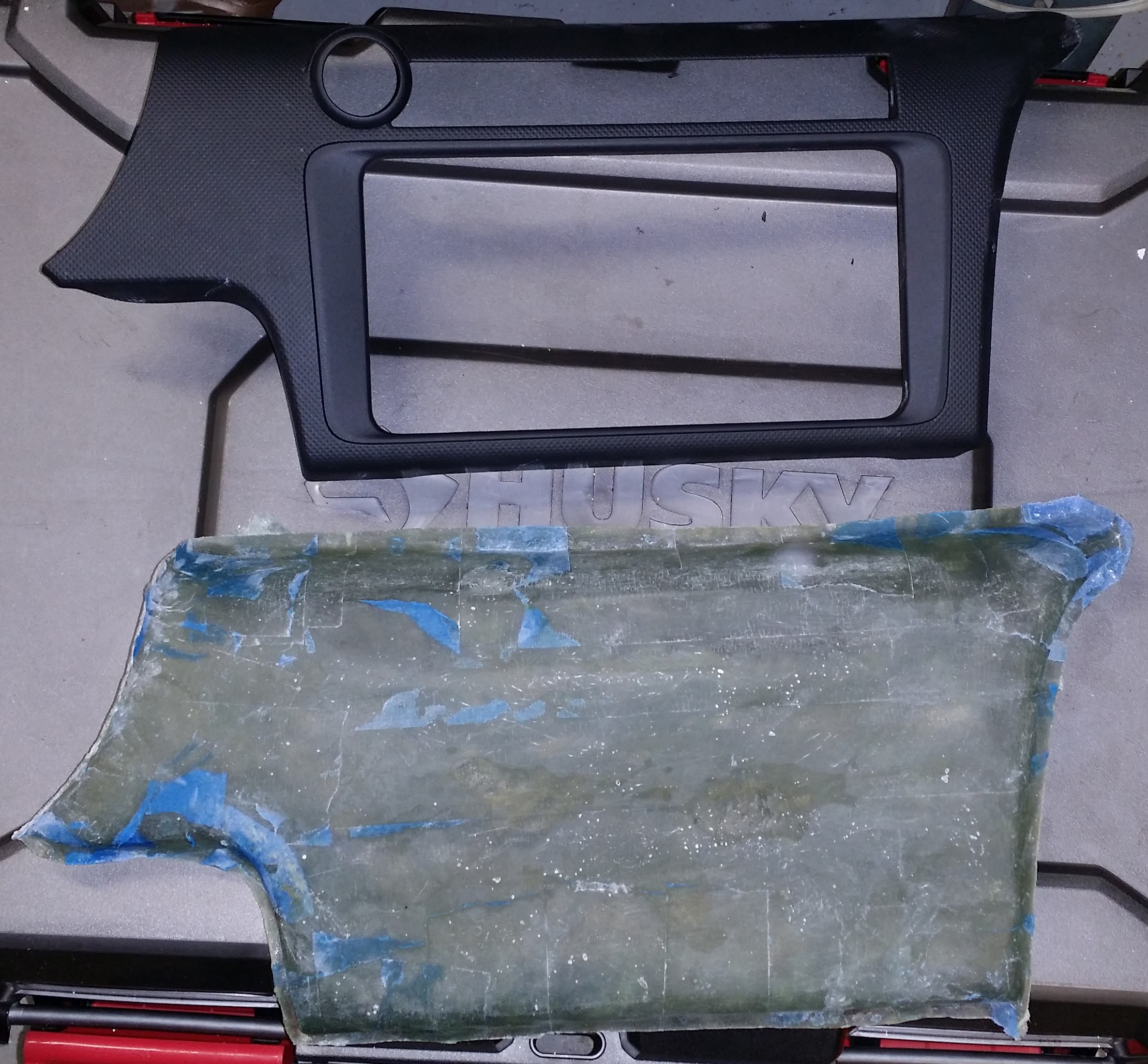


 HybridAir
 CriptasticHacker
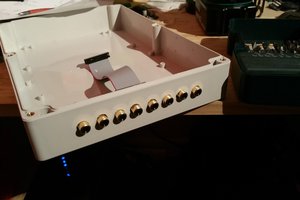
 Matt
Matt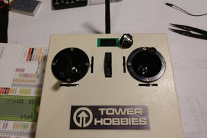
 Rudolph
I just came across your project, and it's similar to my eventual goal for my Subaru Outback. Right now, I've just been working on the stereo replacement, which is using pretty much the same design as yours: a Raspberry Pi with a 7" touch screen. It also includes a backup camera, and I've written my own interface software for it using Python and Kivy. That project can be found at https://hackaday.io/project/157460-censh . Currently, I'm not looking at integrating climate controls, though I may do that in the future. For now, I'd be happy to get it consistently playing Bluetooth audio without hiccups, and able to display navigation directions.