Background https://en.wikipedia.org/wiki/Precision_rectifier and links
Proof of concept:
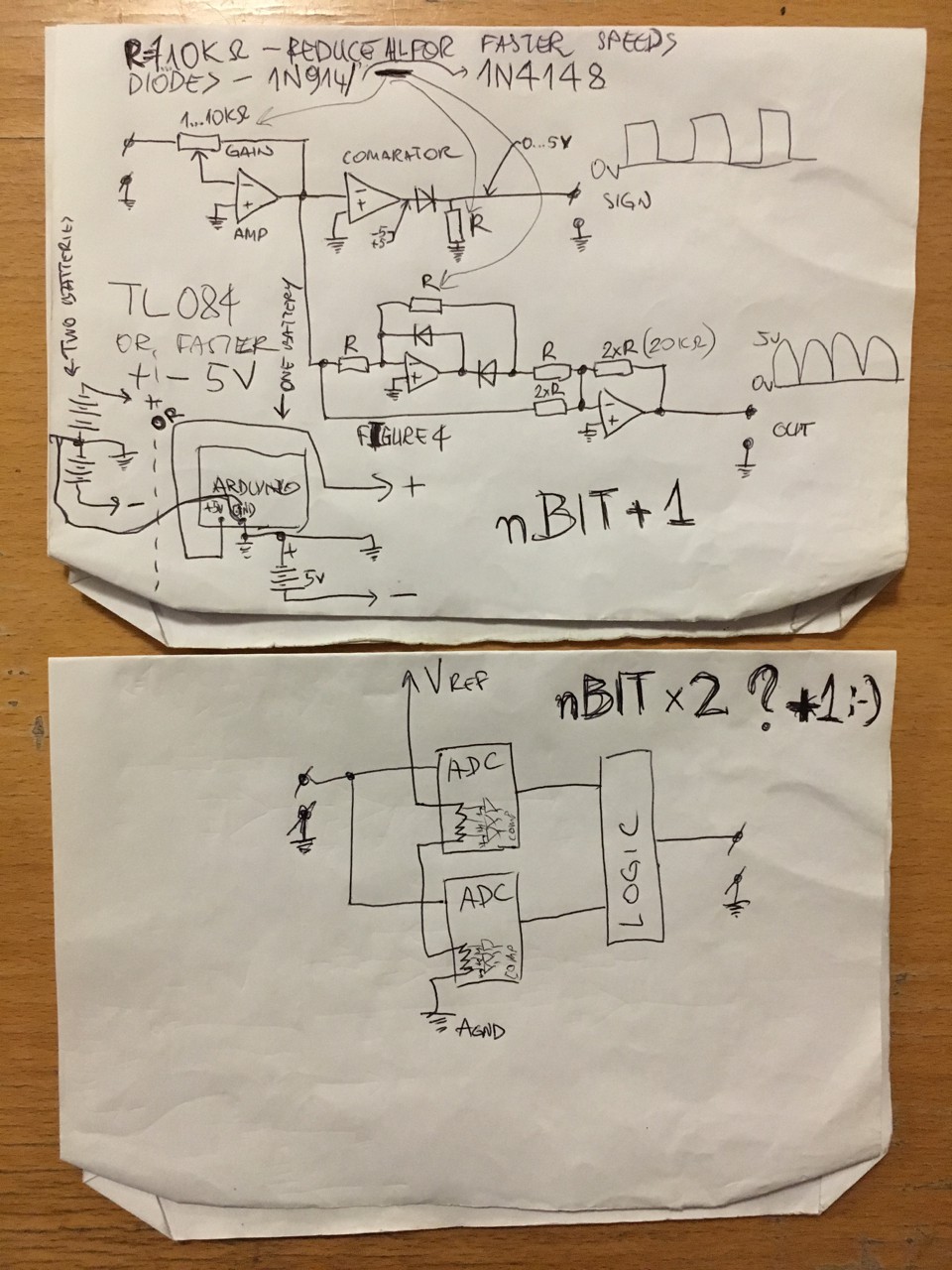
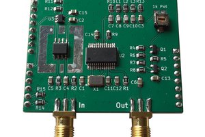
Tune the comparator for zero-crossing detection - this will give as a sign + or -
Rectify AC in to DC
Sign the ADC value depending on comparator output
This gives signed +10Bit and -10Bit values on arduino, so -1023...0...+1023 = 2048 = 10Bit + 1 = 11Bit Bipolar ADC! (haha, not quite 12Bit Uno(Due yes) & not quite x2 resolution as mentioned on GitHub :D)
The first op-amp is used as a comparator
The second amplifies the signal,
The last Two op-amps were used for rectifier: Figure 4 http://sound.whsites.net/appnotes/an001.htm (will upload pdf to files, just in case :D)
Binkin' pin #13 is the blue line on the scope(the sign), red is the rectified AC/DC Plotting float with added sign. See the Arduino sketch for more logic.
There must be a way to bias it out without the diodes :D Shout if you know ;)
--
ADDING VERTICAL RESOLUTION:
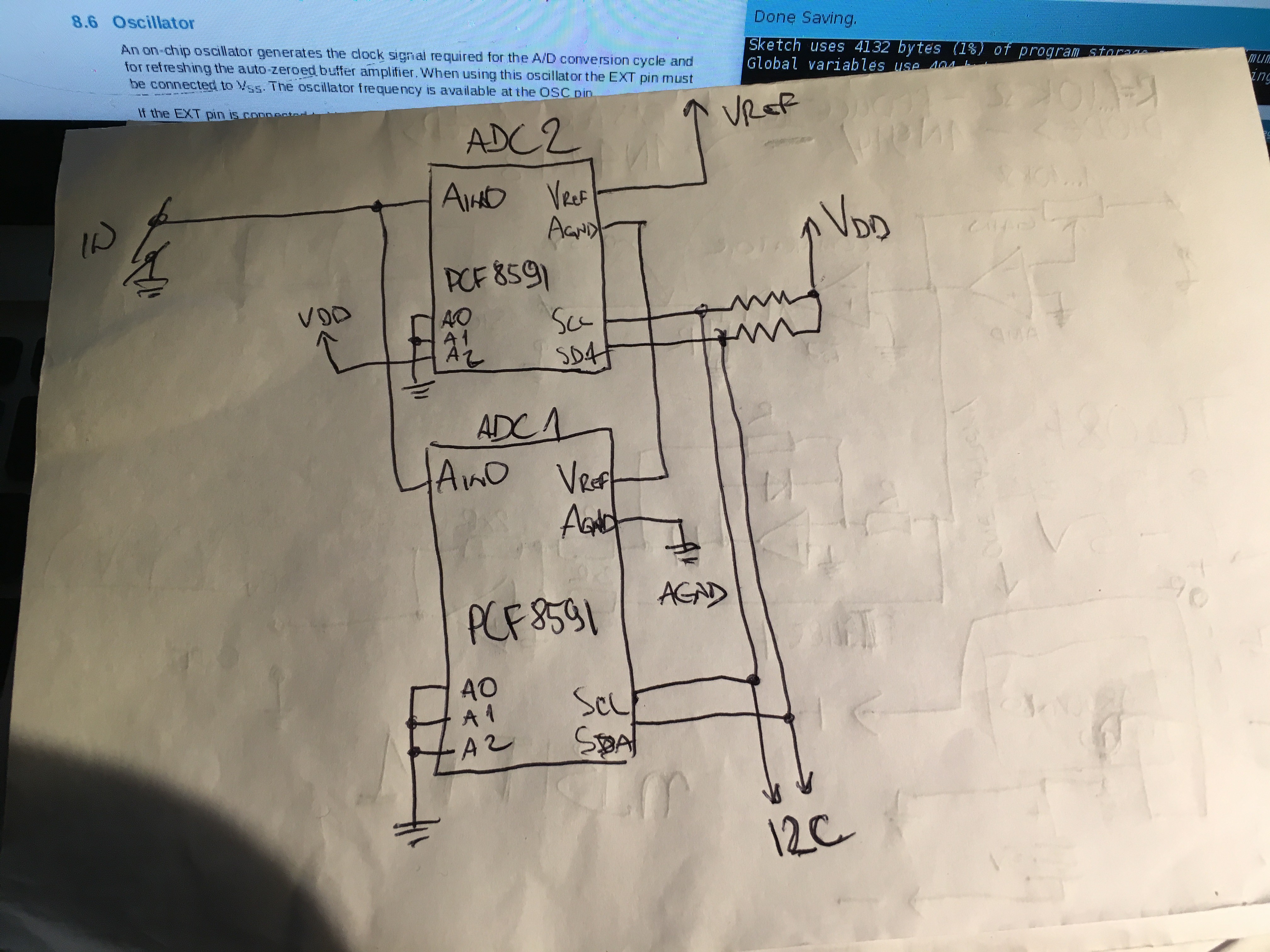
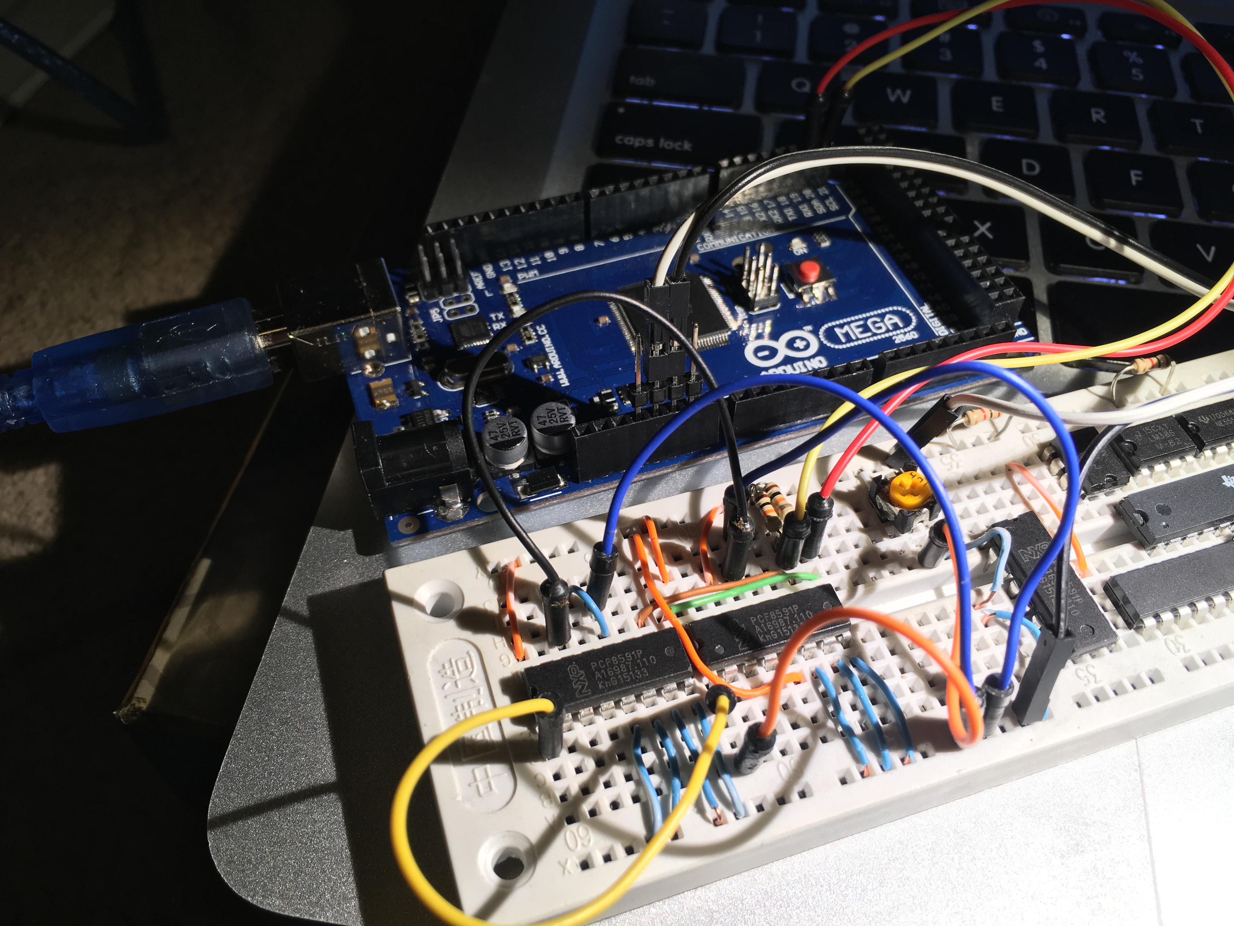
This time using PCF8591. Connect both inputs together, and internal 100kΩ resistors in series, then sum both results together. Sample rate decreases by 2 but, this doubles the numeric resolution from 256 to 512 and Bitwise resolution from 8 to 9Bit. Both ADCs should be synchronised and sample at the same time (in this example I did not bother)
FLASH ADC
Theoretical thoughts on Flash ADC and imaginary schematic
One could use any comparators, I selected linear LM3914 for simplicity
Not sure of LM3914 speed, also take into account logic propagation delays
Priority encoders don’t seem to mind the output of previous stages(see the truth table) and LM3914 has the capability of operating in DOT mode which might suggest power savings.
Lets asume two digits with a dot in between and a 10 Volt ref.
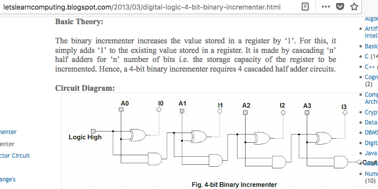
7.4V on the input: the first flash would show 7 and produce binary representation of 7 on the output. We then increment 7 by 1 using 4Bit Binary Incrementer. Decode both values to analog and use it as a reference for the second flash stage to set the low and high Vref. The second flash should read 4, and display 7.4Volt. It would produce 4 & 4 bits, making it a nice 1 byte of data
The schematic is not tested, as I have no components, too poor and live in the kitchen on 24hour move out notice
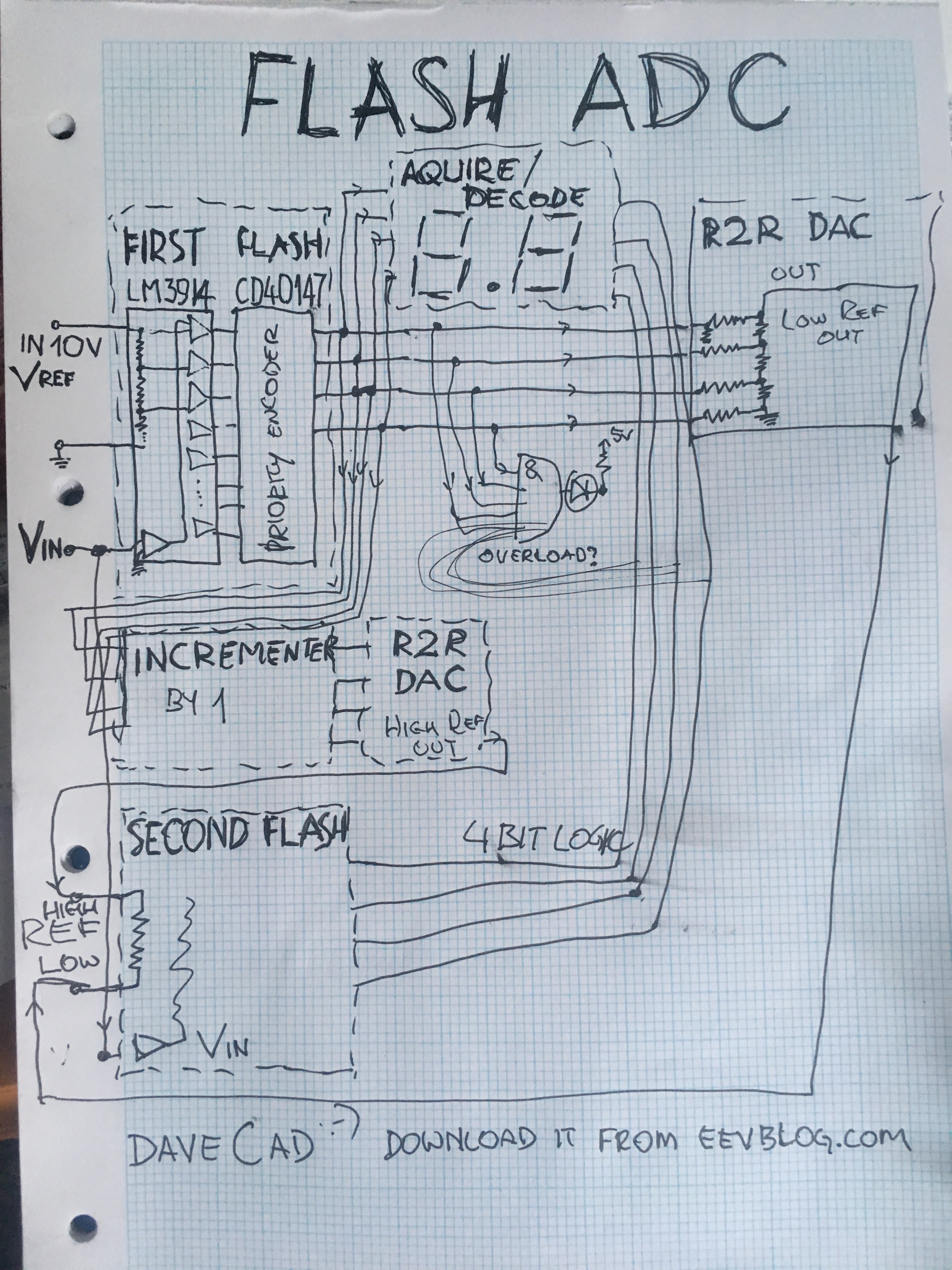 The incrementer logic is made up of four half-adders http://letslearncomputing.blogspot.com/2013/03/digital-logic-4-bit-binary-incrementer.html
 Gintaras Valatka

 SHAOS
SHAOS
 Jithin
 adria.junyent-ferre
Changing the world Bit by Bit :D https://hackaday.com/2018/05/07/double-the-resolution-from-an-arduino-adc/
Unfortunately, I have to go begging for food first, before I can continue. Be patient.
To be continued...